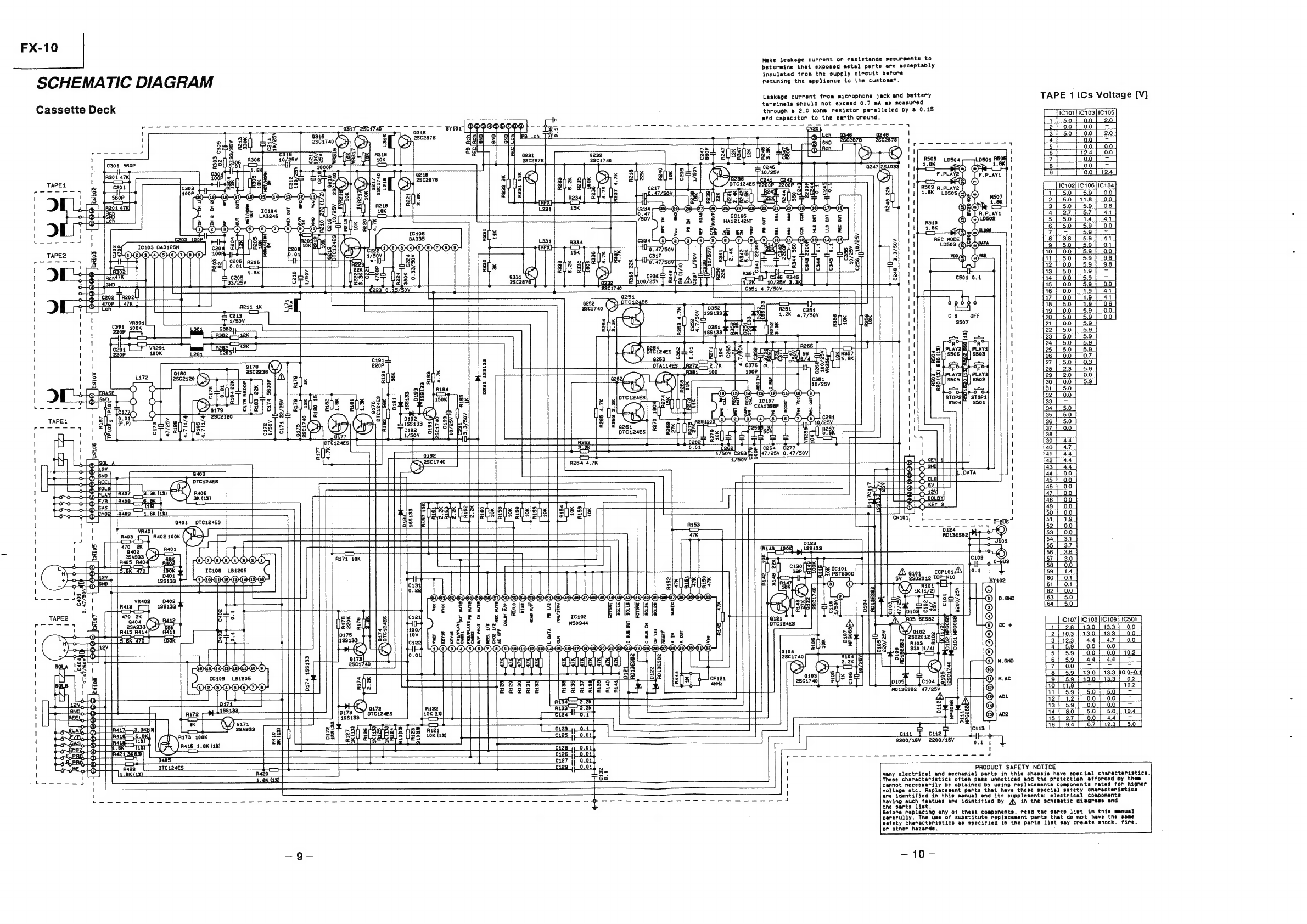
Hitachi FX-10 User manual

olad
3.3
TaN
el
a
Mee
LL
No.so7e
|
FX-10
SERVICE
MANUAL
[E,
Z,
Bl
CAUTION
DANGER
Invisible
laser
radiation
when
open
and
interlocks
failed
or
defeated.
AVOID
DIRECT
EXPOSURE
TO
BEAM.
GEFAHR
Unsichtbare
Laser-Strahlung
wenn
Interlock
(Blockierung)
funktionsuntichtig
oder
abgeschaltet.
UNMITTELBAREN
KONTAKT
MIT
DEM
STRAHL
UNBEDIGT
VERMEIDEN.
DANGER
Faire
tres
attention
aux
radiations
émises
par
le
faisceau
laser
invisible
au
défaillance
du
verrouillage.
NE
JAMAIS
S'EXPOSER
DIRECTEMENT
AU
FAISCEAU.
VARNING
Nér
apparaten
Sppnats
och
skyddsanordningen
felar
eller
satts
ur
funktion
férekommer
osynlig
laserstralning.
UNDVIK
DIREKTE
BESTRALING.
ADVARSEL
Nar
apparatet
abnes
og
beskyttelsesanordningen
ikke
virker
eller
szettes
un
af
funktion,
forekommer
der
usynlig
laserstraling.
UNDGA
DIREKTE
BESTRALING.
ADVARSEL
Nar
denne
delen
er
apen
som
falge
av
at
lasen
er
utkoplet,
eller
ikke
fungerer,
eksisterer
det
usynlig
laserstraling.
UNNGA
A
BLI
UTSATT
FOR
DIREKTE
BESTRALING!
VARIOITS
Laite
lahettaa
nakymaténta
lasersdteilya,
kun
se
avataan
ja
kun
sisdiset
turvalukot
eivat
toimi.
VARO
JOUTUMASTA
ALTTIIKS!
SATEILYLLE.
CONTENTS
SPECIFICATIONS
WIRING
DIAGRAM
D-10
EXPLODED
VIEW
DISASSEMBLY
INSTRUCTIONS
PARTS
LIST
STANDARD
MAINTENANCE
DA-10
ELECTRICAL
ADJUSTMENT
DISASSEMBLY
INSTRUCTIONS
SCHEMATIC
DIAGRAM
INSTRUCTION
FOR
HANDLING
PWB
BOTTOM
VIEW
OPTICAL
SYSTEM
BLOCK
PICKUP
WIRING
DIAGRAM
PRECAUTIONS
FOR
CHECKING
BEAM
EXPLODED
VIEW
EMISSION
OF
LASER
DIODE
PARTS
LIST
PICKUP
REPLACEMENT
HMA-10
CD
ADJUSTMENT
DISASSEMBLY
INSTRUCTIONS
TROUBLESHOOTING
ADJUSTMENT
SCHEMATIC
DIAGRAM
SCHEMATIC
DIAGRAM
PWB
BOTTOM
VIEW
PWB
BOTTOM
VIEW
WIRING
DIAGRAM
WIRING
DIAGRAM
EXPLODED
VIEW
EXPLODED
VIEW
PARTS
LIST
PARTS
LIST
:
HS-FX10
HPT-10/HMA-10
DISASSEMBLY
INSTRUCTION
DISASSEMBLY
INSTRUCTIONS
SCHEMATIC
DIAGRAM
TUNER
ALIGNMENT
WIRING
DIAGRAM
SCHEMATIC
DIAGRAM
EXPLODED
VIEW
PWB
BOTTOM
VIEW
PARTS
LIST
SAFETY
PRECAUTION
following
precautions
should
be
observed
when
servicing.
Since
many
parts
in
the
unit
have
special
safety-related
characteristics,
always
use
genuine
Hitachi's
replacement
_
parts.
Especially
critical
parts
in
the
power
circuit
block
should
not
be
replaced
with
other
makers.Critical
parts
are
marked
with
A
in
the
circuit
diagram
and
printed
wiring
board.
:
ae
2.
Before
returning
a
repaired
unit
to
the
customer,
the
service
technician
must
thoroughly
test
the
unit
to
ascertain
that
it
is
completely
safe
to
operate
without
danger
of
electrical
shock.
The
1.
SPECIFICATIONS
AND
PARTS
ARE
SUBJECT
TO
CHANGE
FOR
IMPROVEMENT
COMPACT
DISC
STEREO
SYSTEM
—
__.,
July
1992
Consumer
Electronics
Division

FX-10
The
caution
labels
on
laser
usage
DA-10
CAUTION:
INVISIBLE
LASER
RADIATION
WHEN
OPEN
AND
INTERLOCKS
DEFEATED
AVOIDEXPOSURE
70
BEAM
ARSEL:
pores
LASERSTRALING
VED
ABNI
SIKKERHEDSAFBAYDERE
€R
UDE
AF
FUNKTION
UND!
ease
TENSE
FOR_STRALING.
;
AVATTAESSA
af
SUQJALUKITUS OHITETTAESSA
OLET
Ara
NAKYMATTUMALLE
LASERSATEILYLLE
ALA
KATSO
Cc
LASS
1
VARNING:
—_
OSYNLIG
LASERSTRALNING
NAR
DENNA
DEL
AR
LASER
PRODUCT
OPPNAD
OCH
SPARREN
AR
URKOPPLAD
BETRAKTA
EJ
STRALEN!
HITACHI
sectto
DA-to
MADE
IN
SINGAPORE
HECHO
EN
SINGAPUR
Hitachi
Ud
__
FABRIQUE
A
SINGAPOUR
SPECIFICATIONS
e
Preamplifier-Tuner
(HPT-10)
Dynamic
bass:
7OHz
10
dB
e
Accessories
Tuning
range:
FM
:
87.5
to
108.0MHz
(SOKHz
step)
Signal
to
Noise
ratio:
96dB
AM
foop
antenna:
1
MW:
522
to
1,611kHz
(9kHz
step)
Antenna
holder
and
screws:
Iset
LW
:
153
to
281kHz
(kHz
step)
e
CD
Player
(DA-10)
System
connector
cable
(9P):
1
Sensitivity
(S/N
26dB):
FM
:
1.54V
Frequency
response:
5
to
20,000Hz
System
connector
cable
(15P):
1
MW:
61dB/m
Dynamic
range:
98dB
Pin
cord
(2P):
1
LW
:
68dB/m
Signal
to
noise
ratio:
103dB
Pin
cord
(1P):
2
Signal
to
Noise
ratio
Distortion
(1kHz):
0.007%
Remote
control
(RB-10)
1
(mono):
70dB
Separation
(1kHz)
97dB
Separation
(Stereo):
40dB.
input
sensitivity:
Aux
300mV/47kohms
e
General
Specifications
Phono
3mvV/47kohms
(switchable)
Power
supply:
AC230V,
50Hz
[E,Z]
DAT
300mvV/22kohms
Power
consumption:
330W
AC240V,
50Hz
[B]
Output/impedance:
DAT
rec
200mV/tkohms
Dimensions:
Pre
out
200mV/1kohms
CD
Player:
225
(W)
x
83
(H)
x
262
(D)
mm
Frequency
response:
10
to
20,000Hz
(DAT)
Preamplifier-Tuner:
225
(W)
x
83
(H)
x
275(D)
mm
Distortion
(1kHz):
0.005%
Tape
Deck:
225
(W)
x
115
(H)
x
262
(D)
mm
Signal
to
Noise
ratio:
95dB
Power
Amplifier:
225
(W)
x
115
{H)
x
321
(D)mm
Tone
control:
Bass
+/-8dB
(100Hz)
Weight:
Treble
+/-8dB
(10kHz)
CD
Player:
2.0kg
Preamplifier-Tuner:
—1.8kg
e@
Tape
Deck
(D-10)
Tape
Deck:
2.8kg
Frequency
response:
Nor:
40
to
15,000Hz
Power
Amplifier:
5.9kg
CrO2
:
40
to
16,000Hz
Timer
accuracy:
Within
60
seconds
at
monthly
Metal
:
40-17,000Hz
rate
Signal
to
Noise
ratio:
72dB
(Dolby
C
on)
56d8
(Dolby
off)
e@
Speaker
Systern
(HS-FX10)
Wow
flutter:
0.08%
wrms
System:
16cm
3-way
speaker
system
Impedance:
6ohms
@
Power
Amplifier
(HMA-10)
Max.
Power
(Music):
100W
Output
power:
SOW
+
50W
0.02%
(SINUS)
Dimensions:
199
(W)
x
396
(H)
x
255
(D)
mm
Distortion
(1/42P):
0.015%
Weight:
10kg
Frequency
response:
10
to
50,000Hz
Specifications
are
subject
to
change
without
Input
sensitivity:
200mV/47kohms
notice
for
performance
inprovement.
Check
that
exposed
parts
are
acceptably
insulated
from
the
supply
circuit
before
returning
the
instrument
repaired
to
the
customer.
INSTRUMENT
-
Checking
method
|
Power
(Operate)
switch
is
set
to
ON.
(Exposed
part)
Next,
measure
the
resistance
value
between
the
both
poles
of
attachment
cup
(Power
supply
plug)
and
the
CD
OUT
terminal
of
rear
plate
and
check
that
the
resistance
value
is
500
kohms
or
more.
Insulation
tester
(DC
500V)

DISASSEMBLY
INSTRUCTIONS
CASSETTE
DECK
1.
Open
the
cassette
covers
and
take
out
the
cassette
tapes.
2.
Remove
five
screws
(@
holding
the
metal
case.
3.
Remove
six
screws
holding
the
cassette
mechanism
set.
Figure
1
5.
Remove
a
screw
©
and
eight
screws
©
holding
the
cassette
mechanism.
6.
Push
two
tabs,
take
out
the
cassete
lid.
Figure
3
FX-10
Remove
eight
screws
©
_
holding
the
deckamplifier
PCB.
Figure
2

FX-10
|
STANDARD
MAINTENANCE
Whenever
a
unit
is
brought
in
for
service
or
repair,
it
should
be
cleaned
and
lubricated
and
the
head
should
be
demagnetized.
1.
Cleaning:
Clean
the
head
and
all
tape
handing
surfaces
using
standard
cleaner
and
cotton
swabs.
Wipe
dry.
2.
Demagnetization:
Do
not
use
magnetized
tools
near
the
head,
since
they
can
magnetize
it.
With
normal
use,
the
head
with
retain
small
amounts
of
residual
magnetism
which
results
in
increased
noise
and
loss
of
high-frequency
response.
Use
a
standard
tape
head
demagnetizer
to
demagnetize
the
playback
head.
3.
Lubrication:
Use
a
high-grade
of
specially
formulated
lubricant
in
the
appropriate
places.
Lubrication
is
normally
required
only
when
parts
tend
to
bind,
or
after
long
period
of
use.
Use
all
lubricants
sparingly
and
avoid
contact
with
other
parts.
ELECTRICAL
ADJUSTMENT
Pre-Adjustment
Procedures
1.
Be
sure
to
demagnetize
and
clean
the
head
before
proceeding
with
head
adjustment.
2.
Never
use
a
magnetized
screwdriver
for
the
head
adjustment.
Tape
Speed
Adjustment
(Figure
4)
a
ae
Connect
a
Frequency|
Cassette
1
|
Cassette
1
FIR
|
|
vRa01
*
Test
Tape:
MTT-111N
Counter
to
the
CN201
*
2940Hz~3060Hz
of
Fig.
4.
Cassette
2
F/R
VR402
Set
(Deck)
Frequency
Counter
[Sd
Figure
4

FX-10
Playback
Head
Azimuth
Adjustment
(Cassette
1)
(Figures
5
and
6)
1.
Connect
and
output
meter
or
oscilloscope
to
each
of
the
CN201.
2.
Playback
and
12.5
kHz
test
tape
and
turn
the
azimuth
adjustment
screw
to
obtain
the
maximum
output
level
of
the
left
and
right
channels,
in
the
forward
and
reverse
play
modes.
3.
When
the
output
level
of
the
left
and
right
channels,
and
forward
and
reverse
position
differs,
readjust
to
the
make
the
both
channels,
and
both
directions
at
the
same
level.
4.
After
adjustment,
secure
the
screw
with
lock
paint
or
glue.
Record/Playback
Head
Azimuth
Adjustment
(Cassette
2)(
Figures
5
and
6)
1.
Connect
and
output
meter
or
oscilloscope
to
each
of
the
CN201.
2.
Playback
and
12.5
kHz
test
tape
and
turn
the
azimuth
adjustment
screw
to
obtain
the
maximum
output
level
of
the
left
and
right
channels.
3.
When
the
output
level
of
the
left
and
right
channels
differs,
readjust
to
make
the
both
channels
at
the
same
level.
4.
After
adjustment,
secure
the
screw
with
lock
paint
or
glue.
Set
(Deck)
Output
Meter
i
——rs
Gnd
——C)
Figure
5
Figure
6

FX-10
Playback
Level
Adjustment
(Figure
7)
[seo]
connect
[song
[Aaun
|
omens
=i
Cassette
1
L-ch
VR217
R-ch
VR317
Cassette
2
L-ch
VR216
R-ch
*
Output
Level
580mV
+2dB
*
Test
Tape:
MTT-150
Connect
a
Output
Meter
to
the
CN201
of
Figure
7.
Bias
Frequency
Adjustment
(Cassette
2)
(Figures
8
and
10)
sof
men
[sete
[rome
[pee
L172
*
105kKHz
+1kHz
Recording
Level
Adjustment
(Cassette
2)
(Figure
9)
Metal
Position
Rec
mode
Connect
a
Frequency
Counter
to
the
TP101
(Bias)
and
TP102
(Gnd).
(Figures
8
and
10)
Connect
a
Output
Meter
to
the
CN201.
Connect
a
Audio
Signal
Generator
to
the
“AUX”
terminal
of
Pre-Tuner
section.
(Figure
9)
Set
the
Deck
REC/
PAUSE
mode
with
normal
Tape.
Adjust
the
level
of
L/R
of
410mV
the
Audio
Signal
Generator.
Record
and
playback.
*
REC/Playback
Level
410mV
+0.5dB

Bias
Current
Adjustment
(Cassette
2)
(Figure
9)
Deck
Amplifier
PWB
Top
View
Connect
Output
Meter
to
the
CN201.
Connect
a
Audio
Signal
Generator
to
"AUX”
terminal
or
Pre-Tuner
section.
(Figure
9)
Set
the
Deck
REC/
PAUSE
mode
with
CrO2
Tape.
Adjust
the
level
of
41imV
at
CN201
the
Audio
Signal
L/R.
Generator.
Record
and
playback
«
REC/Playback
Level
41mV
+0.5dB
—
0dB
Set
(Deck)
Output
Meter
Frequency
Counter
L@-L-G0E-B208
Figure
10
l
|
Gnd
Gnd
A
countermeasure
of
statical
electricity
(Figure
11).
Connect
a
ceramic
capacitor
0.1
UF
the
chassis
to
deck
Figure
7
Figure
8
display
PWB.
Set
(Pre-Tuner)
Set
(Deck)
Audio
Signal
Generator
Output
Meter
I
I
Gnd
Figure
9
Figure
11
ae
-7T-
Sg:

FX-10
Cer
ete
a
1
2
|
i
k
te
Teno
Fs
Tal
a
Make
leakage
current
or
resistande
mesurments
to
betermine
that
exposed
metal
parts
are
acceptably
insulated
from
the
supply
circuit
before
SCHEMATIC
DIAGRAM
ratiininy
the.
sppience
to:
the
custoner
Leakage
current
from
microphone
jack
and
battery
terminals
should
not
exceed
0.7
mA
as
measured
Passette
Deck
through
a
2.0
kohm
resistor
paralleled
by
a
0.45
mfd
capacitor
to
the
earth
ground.
10104
LA3246
1C4103
BA3126N
C248
=3.3/50V
We
5
s+
EB
a
re
reel
Oe
OS
Ca
Gas
RE
ala
O13
|
ow
pots
=
ats
ale
seks
Ras
poe
toute)
|
woul
ee
83
BS
ge
qcio7
5
we
CXAS398P
8
28
c
A253
4.7
—
4100/2
iV
&
Ss
nN
a
M
n3(]o]
SG
[|
ceee’
peal
i;
pd
KEY
See
sear
seconn
Pree
0008,
ty
PS
“ar
DTCi24ES
[yy
Peck
Oly
Pe
sv
R406
©
=
F
6
o
ce
a
ct
ee
a
ad)
ee
er
ne ee
ee
he
gs
ee
Se
A
a
ee
a
fan
i
ee
a
oe
a
a5
|_|
ite
Rabe
ete
ae
2
a
oh
aes
a
pa03
f
Ue)
ei
snes
as
se
a
sew
ie
$466
©
Fa
—
-—.
.
.
+
ii
Pee
iaaa({{{(|
pence
Sh
ee
le
ela
:
|
©
¢
5sv__2sp2012
ICP-N40
Oey
ay
QOVOOOOO
OSE
4
FOO,
i,
BI
|
ia
:
Eses
aii
re
eh
iar
3
vr4o2
0402
18S133
Y
'
Rags
Rata
441
a102_
wi
ag
Ve
Bre
Teka
=
wy)
2so20128/
FF
Peril
as
mae:
een
wR
Reeds
bel
a.
|
sey
SS
HHIODOHIO®
()
a
:
is
it
re
POPPOOOD
174
2
us
SS
aw
D
the
parts
list.
or
other
hazards.
i*]
ay
ind
ud in
IND
i—_
i
js
1
iN
ian
J
i~
>
©
ko
loin
On
|
~
wn
IND]
ala
on
bn
©
ler
rate
lo lo
ole
jo
PRODUCT
SAFETY
NOTICE
Many
electrical
and
mecnanial
parts
in
this
chassis
neve
special
characteristics.
These
characteristics
often
pass
unnoticed
and
the
protection
afforded
by
them
cannot
necessarily
be
obtained
by
using
replacements
components
rated
for
higher
voltage
etc.
Replacement
parts
that
nave
these
special
safety
characteristics
are
identified
in
this
manual
and
its
supplements:
electrical
components
having
such
featues
are
idintified
by
#\
in
the
schematic
diagrans
and
Before
replacing
any
of
these
components.
read
the
parts
list
in
this
manual
carefully.
Tne
use
of
substitute
replacement
parts
that
do
not
have
tne
same
safety
characteristics
es
specified
in
tne
parts
list
may
create
shock.
fire.
TAPE
1
ICs
Voltage
[V]
[
Jicror}ic103]IC105
[3{
50
[
oo]
20
|
i
Njo
BIO
1€102]1C106]1C10:
tnJolofaurjr
onjon
enfun
co
II
1D
100
1
D
KO
(a)
ire)
INC
in
ESE
S
—
Bed
ford
ea)
en
fonin
en
co
oo
|
In
bee
ie
ROJO
|o|N
fans}
L
4]
|
2
|
[3
|
[4
|
[5
|
[6
|
[
8
|
[9
|
141
|
112
|
[43
|
[14
|

FX-10
PWB
BOTTOM
VIEW
NOTE
TAPE
2
ICs
Voltage
[V]
TAPE
1
}
The
Original
PWB
Top
View.
emi
fcvoa
es
Transistor
Voltage
[V]
Cassette
Deck
Switch
Electrical
capacitors:
@
mark
is
plus
side.
bars
md
ae
Hime
eam
:
rie
ie
a405
To.0
[|
0.0
[
00
|
TAPE
2
Transistor
Voltage
[V]
Cc
[Q702
[13.0
[16.9
|
12.4
|
Ras)
ND|—
kes
i
rN
wo
lololo
o
olololololclolo
jalalo
lo
rei
NE
lolalo
olole
ojos
of
wo
loin
eo
SEE
PEERS
URED
er
BEES
ee
Voltage
check
position:
Play/Forward
position

X-10
WIRING
DIAGRAM
Cassette
Deck
MOTOR
MOTOR
DECK
AMP.
PW.B.
=
R/P
HEAD
~
DECK
DISPLAY
PW.B.
a

|
FX-10
EXPLODED
VIEW
Cassette
Deck
Mechanism(Cassette
1)

FX-10
EXPLODED
VIEW
Cassette
Deck
Mechanism(Cassette
2)

FX-10
EXPLODED
VIEW
Cassette
Deck
Cabinet
236
DECK
_AMP._PWB.

FX-10
PARTS
LIST
PRODUCT
SAFETY
NOTE:
Components
marked
with
a
A
have
special
characteristics
important
to
safety.
Before
replacing
any
of
these
components,
read
carefully,
the
PRODUCT
SAFETY
NOTICE
of
this
Service
Manual.
Don’t
degrade
the
safety
of
the
receiver
through
improper
servicing.
ABBREVIATIONS:
Capacitors
CC:
Cylindrical
ceramic,
CD:
Ceramic
disc,
MF:
Mylar
film,
EL:
Electrolytic,
ST:
Styrol
Resistors
CF:
Carbon
film,
RN:
Metal
film,
CS:
Oxide
metal
film,
FR:
Fuse
resistor
Semiconductor
Q:
Transistor,
D:
Diode,
IC:
IC
Cassette
Deck
pes
PART
No.
DESCRIPTION
PWB
ASSEMBLY
PART
No.
DESCRIPTION
Not
used.
2940-605-0-00
Deck
amplifier
PWB
ass
(with
display
PWB)
9301-455-6-15
560PF
+10%
9301-454-7-15
470PF
+10%
9301-451-0-15
100PF
+10%
9301
-451-0-15
100PF
+10%
0937-833-3-06
33
UF
+20%
9335-451
-0-34
0.01
pF
+5%
Not
used.
9335-451
-0-34
0.01
HF
6+5%
Not
used.
0937-850-1-06
1uF
+
20%
9364-121-0-16
100
uF
8
+20%
9364-121-0-16
100
HF
+20%
0937-850-1-06
1
HF
+20%
0937-851-0-06
10
pF
+
20%
Not
used.
0937-851
-0-06
10
BF
+
20%
0937-854-7-96
O47
NF
+20%
9301-451-0-25
1000
PF
+10%
Not
used.
Not
used.
9335-454-7-24
4700
PF
0937-850-1-06
Tyr
0937-851-5-96
0.15
pF
0937-853-3-96
0.33
pF
CAPACITORS
0937-732-2-26
EL,
2200uF
+20%
0937-834-7-06
EL,
47
uF
+
20%
0937-834-7-06
EL,
47
uF
+
20%
0937-834-7-06
EL,
47
pF
+
20%
0937-832-2-16
EL,
220uF
+20%
0937-851-0-06
EL,
10pF
+
20%
Not
used.
Not
used.
:
9302-351-0-49
CC,
0.1HF
=
+80/-20%
Not
used.
0937-722-2-26
EL,
2200pF
+20%
0937-722-2-26
EL,
2200uF
+20%
9302-351
-0-49
0.1
UF
+80/-20%
Not
used.
Not
used.
0937-850-1-06
1uF
+
20%
0937
-834-7-06
47
pF
+
20%
Not
used.
0937-811-0-16
+20%
9302-021-0-35
+10%
9302-351-0-49
+80/-20%
9302-351-0-49
+80/-20%
9302-021-0-35
+£10%
9302-021-0-35
+10%
9302-021-0-35
+10%
9302-021-0-35
+10%
9302-021-0-35
+10%
9301-153-3-04
+5%
0933-452-2-44
+5%
9302-351-0-49
+80/-20%
Not
used.
0937-853-3-86
33
1F
Not
used.
Not
used,
0937-854-7-96
0.47
UF
Not
used.
0937-831
-0-16
100
HF
0937-850-1-06
1pF
0937-851
-0-06
10
pF
0937-850-1-06
1
HF
Not
used,
9335-452-2-24
2200
PF
9335-452-2-24
2200
PF
9335-452-2-24
2200
PF
0933-451
-0-44
0.1
WF
0933-451-0-44
0.1
HF
0937-851-0-06
10
pF
9301-456-8-15
680
PF
0937-853-3-86
3.3
WF
Not
used.
Not
used.
0937-854-7-86
4.7
UF
0937-854-7-86
4.7
pF
Not
used.
0937-832-2-06
22
UF
0937-850-1-06
THF
0937-834-7-06
47
BF
9335-455-6-24
5600
PF
9335-455-6-24
5600
PF
9335-451
-0-34
0.01
pF
9330-67
1-0-34
0.01
HF
Not
used.
9301-452-2-15
0937-850-1-06
0937-851-0-06
Not
used.
0937-851
-0-06

Set
PART
No.
DESCRIPTION
Not
used.
Not
used.
0937
-853-3-86
Not
used.
Not
used.
0937-850-1-06
0937-850-1-06
0937
-834-7-06
0937-854-7-86
0937
-831-0-16
Not
used.
9301-451
-0-15
0937-854-7-96
Not
used.
0937-851
-0-06
9302-021
-0-35
Not
used.
9301-452-2-15
Not
used.
9302-351
-0-49
+80/-20%
Not
used.
9301-455-6-15
CC,
S60PF
+10%
50V
9301-454-7-15
CC,
470PF
+10%
50V
9301-451-0-15
CC,
100PF
+10%
50V
9301-451-0-15
CC,
100PF
+10%
50V
0937-833-3-06
EL,
33pF
+20%
25V
9335-451
-0-34
+5%
Not
used.
0937-851
-0-06
0937-854-7-96
Not
used,
0937-854-7-96
Not
used.
9335-452-2-24
MF,
2200PF
+5%
50V
9335-452-2-24
MF,
2200PF
+5%
50V
9335-452-2-24
MF,
2200PF
+5%
50V
0933-451
-0-44
CF,
O1pF
+5%
50V
0933-451
-0-44
CF,
O1HF
+5%
50V
0937-851-0-06
EL,
10pF
+20%
50V
9301-456-8-15
680
PF
Not
used.
0937
-854-7-86
Not
used.
0937-851
-0-06
Not
used.
Not
used.
0937-853-3-86
Not
used.
+10%
+20%
9301-451-0-15
0937-864-7-96
a
eee
PART
No.
DESCRIPTION
Not
used.
0937-851
-0-06
9302-021
-0-35
+
20%
£10%
Not
used.
9301-452-2-15
+10%
Not
used.
0938-954-7-96
EL,
047"F
2+20%
50V
9302-351
-0-49
CC,
0.1
BF
+80/-20%
50V
9302-351-0-49
CC,
0.1
pF
+80/-20%
50V
0938-954-7-96
+
20%
Not
used.
9302-351-0-49
|
CC,
01uF
50V
RESISTORS
+80/-20%
0921-521
-0-24
CF,
1k
ohm
+5%
SRD
1/2P
0921-521-0-24
CF,
1k
ohm
+5%
SRD
=
1/2P
0920-813-3-14
CF,
330
ohm
+5%
SRD
1/4P
0920-862-2-24
CF,
2.2kohm
+5%
SRD
1/6P
0920-861
-0-24
CF,
1k
ohm
+5%
SRD
1/6P
0920-861-0-34
CF,
10k
ohm
*+5%
SRD
1/6P
Not
used.
0920-861-0-34
+5%
SRD
1/6P
CF,
10k
ohm
Not
used.
0926-511
-0-32
RN,
10k
ohm
+1%
SRD
1/4P
0926-511-0-32
RN,
10k
ohm
+1%
SRD
1/4P
0926-519-1-12
RN,
910
ohm
+1%
SRD
1/4P
0926-519-1-12
RN,
910
ohm
+1%
SRO
1/4P
0926-511-0-22
RN,
1k
ohm
+1%
SRD
1/4P
0926-511
-0-22
RN,
1k
ohm
+1%
SRD
1/4P
0926-511-0-22
RN,
1k
ohm
+1%
SRD
1/4P
0920-864-7-34
CF,
47k
ohm
+5%
SRD
1/6P
0920-864-7-34
CF,
47k
ohm
+5%
SRD
1/6P
0920-864-7-34
CF,
47k
ohm
+5%
SRD
1/6P
0920-864-7-34
CF,
47k
ohm
+5%
SRD
1/6P
0920-864-7-34
CF,
47k
ohm
+5%
SRD
1/6P
0920-862-2-24
CF,2.2k0hm
+5%
SRD
=
1/6P
0920-862-2-24
CF,
2.2kohm
+5%
SRD
1/6P
0920-864-7-34
CF,
47k
ohm
+5%
SRD
1/6P
0920-864-7-34
CF,
47k
ohm
+5%
SRD
1/6P
0920-864-7-34
CF,
47k
ohm
+5%
SRD
1/6P
0920-864-7-34
CF,
47k
ohm
+5%
SRD
1/6P
0920-864-7-34
CF,
47k
ohm
+5%
SRD
1/6P
0920-864-7-34
CF,
47k
ohm
+5%
SRD
1/6P
0920-864-7-34
CF,
47k
ohm
+5%
SRD
1/6P
0920-861
-0-34
CF,
10k
ohm
+5%
SRD
1/6P
0920-861
-0-44
CF,100kohm
+5%
SRD
1/6P
0920-861-0-54
CF,
1M
ohm
+5%
SRD
1/6P
0920-864-7-34
CF,
47k
ohm
+5%
SRD
1/6P
0920-862-2-34
CF,
22k
ohm
+5%
SRD
1/6P
0920-861-8-34
CF,
18k
ohm
+5%
SRD
1/6P
0920-862-7-34
CF,
27k
ohm
+5%
SRD
1/6P
0920-861
-0-44
CF,
100kohm
+5%
SRD
1/6P
0920-864-7-34
CF,
47k
ohm
+5%
SRD
1/6P
0920-864-7-34
CF,
47k
ohm
+5%
SRD
1/6P
0920-864-7-34
CF,
47k
ohm
+5%
SRD
1/6P
0920-864-7-34
CF,
47k
ohm
+5%
SRD
1/6P
0920-861
-0-34
CF,
10k
ohm
+5%
SRD
1/6P
FX-10

FX-10
SYMBOL
No.
PART
No,
0920-861
-0-34
0920-861
-0-34
0920-861
-0-34
0920-861
-0-34
0920-861
-0-34
0920-861
-0-34
0920-862-2-24
0920-862-2-24
0920-862-2-24
Not
used,
0920-861
-0-34
0920-861-0-24
0920-861-0-44
0920-862-2-24
0920-862-2-44
0920-862-2-24
0920-864-7-24
0920-861-0-24
0920-861
-2-34
0920-861-5-04
0920-861-3-24
0920-861-6-24
0920-862-2-34
0920-862-2-34
0920-814-7-84
0920-814-7-84
0920-860-1-04
Not
used
0920-865-6-34
0920-865-6-34
0920-864-7-24
0920-861-5-44
0920-861-0-24
Not
used.
0920-864-7-34
0920-864-7-34
0920-868-2-04
0920-861
-2-34
0920-861
-8-34
0920-861
-8-24
Not
used,
Not
used.
0920-861
-0-34
0921
-522-7-14
0920-861-0-24
0920-861
-0-34
0920-863-3-44
Not
used.
Not
used.
0920-861
-0-34
Not
used.
0920-862-2-34
0920-861-0-34
0920-864-7-24
0920-862-2-24
0920-863-3-24
0920-862-2-34
0920-863-9-44
Not
used.
0920-861
-1-34
0920-863-0-24
0920-866-2-24
DESCRIPTION
CF,
10k
ohm
CF,
10k
ohm
CF,
10k
ohm
CF,
10k
ohm
CF,
10k
ohm
CF,
10k
ohm
CF,
2.2k
ohm
CF,
2.2k
ohm
CF,
2.2k
ohm
CF,
10k
ohm
CF,
1k
ohm
CF,
100k
ohm
CF,
2.2k
ohm
CF,
220k
ohm
CF,
2.2k
ohm
CF,
4.7k
ohm
CF,
tk
ohm
CF,
12k
ohm
CF,
15
ohm
CF,
1.3k
ohm
CF,
1.6k
ohm
CF,
22k
ohm
CF,
22k
ohm
CF,
4.7
ohm
CF,
4.7
ohm
CF,
1
ohm
CF,
56k
ohm
CF,
56k
ohm
CF,
4.7k
ohm
CF,
150k
ohm
CF,
1k
ohm
CF,
47k
ohm
CF,
47k
ohm
CF,
82
ohm
CF,
12k
ohm
CF,
18k
ohm
CF,
1.8k
ohm
CF,
10k
ohm
CF,
270
ohm
CF,
1k
ohm
CF,
10k
ohm
CF,
330k
ohm
CF,
10k
ohm
CF,
22k
ohm
CF,
10k
ohm
CF,
4.7k
ohm
CF,
2.2k
ohm
CF,
3.3k
ohm
CF,
22k
ohm
CF,
390k
ohm
CF,
11k
ohm
CF,
3k
ohm
CF,
6.2k
ohm
SEMESe
PART
No.
No.
0920-861-5-34
0920-861-8-44
0920-864-7-24
0920-864-7-24
0920-861-8-34
0920-862-2-34
0920-861-0-34
0920-862-4-24
0920-865-6-24
0920-862-2-34
0920-865-6-14
Not
used,
0920-863-3-24
0920-861-2-34
0920-862-2-34
0921-115-6-04
0920-862-2-34
0920-861
-2-24
0920-863-3-24
0920-864-7-54
0920-863-3-24
Not
used.
0920-861
-0-34
0920-865-6-24
Not
used.
0920-862-2-24
0920-862-2-24
0920-864-7-24
0920-864-7-24
0921-115-6-04
0920-862-7-34
0920-861-1-34
0920-862-7-34
0920-861
-8-44
0920-861
-0-34
0920-862-7-24
0920-861-1-34
0920-861
-5-34
0920-862-7-34
Not
used.
0920-861
-0-34
Not
used.
0920-861-0-14
0920-861
-2-34
Not
used.
0920-864-7-34
0920-864-7-34
0920-868-2-04
0920-861
-2-34
0920-861
-8-34
0920-861
-8-24
Not
used.
0920-861
-0-34
Not
used.
0920-862-2-34
Not
used.
0920-861-1-34
0920-863-0-24
0920-866-2-24
0920-861
-5-34
CF,
15k
ohm
CF,
180k
ohm
CF,
4.7k
ohm
CF,
4.7k
ohm
CF,
18k
ohm
CF,
22k
ohm
CF,
10k
ohm
CF,
2.4k
ohm
CF,
5.6k
ohm
CF,
22k
ohm
CF,
560
ohm
CF,
3.3k
ohm
CF,
12k
ohm
CF,
22k
ohm
CF,
56
ohm
CF,
22k
ohm
CF,
1.2k
ohm
CF,
3.3k
ohm
CF,
4.7M
ohm
CF,
3.3k
ohm
CF,
10k
ohm
CF,
5.6k
ohm
CF,
2.2k
ohm
CF,
2.2k
ohm
CF,
4.7k
ohm
CF,
4.7k
ohm
CF,
56
ohm
CF,
27k
ohm
CF,
11k
ohm
CF,
27k
ohm
CF,
180k
ohm
CF,
10k
ohm
CF,
2.7k
ohm
CF,
11k
ohm
CF,
15k
ohm
CF,
27k
ohm
CF,
10k
ohm
CF,
100
ohm
CF,
12k
ohm
CF,
47k
ohm
CF,
47k
ohm
CF,
82
ohm
CF,
12k
ohm
CF,
18k
ohm
CF,
1.8k
ohm
CF,
10k
ohm
CF,
22k
ohm
CF,
11k
ohm
CF,
3k
ohm
CF,
6.2k
ohm
CF,
15k
ohm
+5%
+5%
t5%
£5%
+5%
+5%
+5%
+5%
+5%
+5%
+5%
+5%
+5%
+5%
+5%
+5%
+5%
+5%
+5%
+5%
+5%
+5%
+5%
+5%
+5%
+5%
+5%
+5%
+5%
+5%
+5%
+5%
+5%
+5%
+5%
+5%
+5%
+5%
+5%
+5%
+t5%
+5%
+5%
+5%
+5%
+5%
+5%
+5%
+5%
+5%
SRD
SRD
SRD
SRD
SRD
SRD
SRD
SRD
SRD
SRD
SRD
SRD
SRD
SRD
SRD
SRD
SRD
SRD
SRD
SRD
SRD
SRD
SAD
SRD
SRD
SRD
SRD
SRD
SRD
SRD
SRD
SRD
SRD
SRD
SRD
SRD
SRD
SRD
SRD
SRD
SRD
SRD
SRD
SRD
SRD
SRD
SRD
SRD
SRD
SRD
DESCRIPTION
1/6P
1/6P
1/6P
1/6P
1/6P
1/6P
1/6P
1/6P
1/6P
1/6P
1/6P
1/6P
1/6P
1/6P
1/4P
1/6P
1/6P
1/6P
1/6P
1/6P
1/6P
1/6P
1/6P
1/6P
1/6P
1/6P
1/4P
1/6P
1/6P
1/6P
1/6P
1/6P
1/6P
1/6P
1/6P
1/6P
1/6P
1/6P
1/6P
1/6P
1/6P
1/6P
1/6P
1/6P
1/6P
1/6P
1/6P
1/6P
1/6P
1/6P

a
eae
PART
No.
DESCRIPTION
CF,180kohm
+5%
SRD
1/6P
CF,4.7kohm
+5%
SRD
1/6P
CF,
4.7k
ohm
0920-861
-8-44
0920-864-7-24
0920-864-7-24
Not
used.
0920-862-4-24
0920-865-6-24
0920-862-2-34
0920-865-6-14
Not
used.
0920-863-3-24
0920-861
-2-34
CF,
2.4k
ohm
CF,5.6kohm
+5%
SRD
_
1/6P
CF,
22k
ohm
+5%
SRD
1/6P
CF,
560
ohm
CF,3.3kohm
+5%
SRD
1/6P
CF,
12k
ohm
Not
used,
0920-861
-2-24
0920-863-3-24
CF,
1.2k
ohm
CF,
3.3k
ohm
Not
used.
0920-861
-0-34
0920-865-6-24
CF,
10k
ohm
CF,
5.6k
ohm
Not
used.
0920-861
-0-14
0920-861
-2-34
CF,
100
ohm
CF,
12k
ohm
Not
used.
0920-866-8-34
0920-861
-0-44
0920-864-7-14
0920-864-7-14
0920-865-6-24
0926-513-0-22
0926-513-3-22
0926-516-8-22
0926-511-6-22
0926-513-0-22
0920-861
-0-44
0920-866-8-34
0920-864-7-14
0920-864-7-14
0920-865-6-24
0926-51
1-8-22
0926-513-3-22
0926-516-8-22
0926-511-6-22
0926-511-8-22
0926-513-0-22
0926-511-8-22
CF,
68k
ohm
+
CF,100kohm
+5%
SRD
1/6P
CF,4700nhm
+5%
SRD
=
1/6P
CF,4700hm
+5%
SRD
=
1/6P
CF,
5.6kohm
+5%
SRD
=
1/6P
RN,
3k
ohm
+1%
SRD
1/4P
RN,3.3kohm
+1%
SRD
1/4P
RN,6.8k
ohm
+1%
SRD
1/4P
RN,1.6kohm
+1%
SRD
=
1/4P
RN,
3k
ohm
+1%
SRO
1/4P
CF,100kohm
+5%
SRD
1/6P
CF,
68k
ohm
+5%
SRD
1/6P
CF,4700hm
+5%
SRD
_
1/6P
CF,
470
ohm
+5%
SRD
1/6P
CF,
5.6kohm
+5%
SRD
1/6P
RN,
1.8k0hm
+1%
SRD
1/4P
RN,3.3k0hm
+1%
SRD
1/4P
RN,6.8k
ohm
+1%
SRD
1/4P
RN,1.6kohm
+1%
SRD
1/4P
RN,1.8k0hm
+1%
SRD
1/4P
RN,
3k
ohm
+1%
SRD
1/4P
RN,
1.8k
ohm
Not
used,
0926-516-2-12
0926-516-8-12
0926-516-2-12
0926-516-8-12
Not
used.
0920-861
-8-24
0920-861
-8-24
0920-861-8-24
0920-861
-8-24
0920-861-8-24
RN,
620
ohm
RN,
680
ohm
+1%
SRD
1/4P
RN,6200hm
+1%
SRD
1/4P
RN,
680
ohm
CF,1.8kohm
+5%
SRD
=
1/6P
CF,1.8k0hm
+5%
SRD
1/6P
CF,1.8k0hm
+5%
SRD
1/6P
CF,1.8kohm
+5%
a5
1/6P
CF,
1.8k
ohm
COILS
0991-401-0-05
LHLO6TB100K,
10
BH
L171
0102
D103
D104
D105
D106
D117
0121
D122
D123
D124
D171
D172
D173
D174
D175
D191
D192
D193
D194
D231
D251
0015-089-0-00
0014-790-0-00
0039-894-0-00
0014-789-0-00
0014-790-0-00
0039-894-0-00
001
4-789-0-00
0915-005-2-02
or
0915-005-2-04
fe)
fe)
fe)
ce]
fe}
ie)
4
4
3
x
s
a4
0915-005-2-02
0915-005-2-04
0915-007-4-02
0915-007-4-03
0915-010-6-02
0915-010-6-02
0915-010-7-02
0915-010-7-03
0915-005-2-02
0915-005-2-04
0915-005-2-04
0915-005-2-02
0915-005-2-04
0915-005-2-02
0915-003-9-00
0915-010-6-02
0915-010-6-02
0915-003-9-00
0915-010-6-02
0915-003-9-00
0915-003-9-00
0915-003-9-00
0915-003-9-00
0915-003-9-00
0915-003-9-00
0915-003-9-00
0915-003-9-00
0915-003-9-00
0915-003-9-00
0915-003-9-00
0915-003-9-00
0915-003-9-00
0915-003-9-00
0915-003-9-00
0915-003-9-00
0916-029-3-00
0916-029-3-00
0916-029-2-00
0916-029-3-00
0916-029-3-00
0911-153-5-00
0037-163-0-00
0911-153-1-00
0911-152-7-00
0911-153-0-00
0911-153-4-00
0911-153-6-00
091
1-152-8-00
0911-152-8-00
0911-153-2-00
Pee
PART
No.
DESCRIPTION
DSC
trans-10
Trap
coil
MPxX
filter
Trap
coil
Trap
coil
MPxX
filter
Trap
coil
FILTER
0038-91
1-0-00
Ceramic,
resonat,
CST4MGW
DIODES
MPGO6B
MPGO6D
MPGO6B
MPGO6D
RD5.6ESB2
RD5.6ESB3
RD13ESB2
RD13ESB2
RD15ESB2
RD15ESB3
MPGO6B
MPGO6D
MPGO6D
MPGO6B
MPGO6D
MPGO6B
188133
RD13ESB2
RD13ESB2
188133
RD13ESB2
1$S133
1SS133
188133
18S133
1SS133
188133
18S133
18S$133
188133
188133
188133
188133
188133
188133
1$$133
1SS133
LED,
SLR-57MC3F
LED,
SLR-57MC3F
LED,
SLR-57VC3F
LED,
SLR-57MC3F
LED.
SLR-57MC3F
ICS
and
TRANSISTORS
PST600D
M50944-179SP
BA3126N
LA3246
BA335
HA12142NT
CXA1398P
LB1205
LB1205
BU2040
FX-10

FX-10
4Q101
03903-008-1-00
2802012
4Q102
0903-008-1-00
28D2012
Q103
0906-203-3-19
28C1740S-S
Q104
0906-203-3-19
28C1740S-S
Q105
0906-203-3-19
28C1740S-S
Q121
0906-203-1-00
DTC124E
or
0906-209-0-00
BA1F4M
or
0906-205-0-00
RN1203
Q122
0906-203-3-19
28C17408-S
Q171
0906-203-4-19
2SA933S-S
Q172
0906-203-1-00
DTC124ES
or
0906-209-0-00
BA1F4M
or
0906-205-0-00
RN1203
Q173
0906-203-3-19
28C1740S-S
Q174
0906-203-1-00
DTC
124ES
or
0906-205-0-00
RN1203
or
0906-209-0-00
BA1F4M
Q175
0906-203-3-19
28C1740S-S
Q176
0906-203-1-00
DTC124ES
or
0906-209-0-00
BA1F4M
or
0906-205-0-00
RN1203
Q177
0906-205-0-00
RN1203
or
0906-209-0-00
BA1F4M
or
0906-203-1-00
DTC124ES
4Q178
0902-005-1-25
28C2236-Y
Q173
0906-207-3-25
2SC2120-Y
Q180
0906-207-3-25
2SC2120-Y
Q191
0906-203-3-19
2SC1740S-S
Q192
0906-203-3-19
28C1740S-S
Q216
0906-203-3-19
2SC1740S-S
Q217
0906-203-3-19
2SC1740S-S
Q218
0906-203-5-02
2SC2878-B
Q219
0906-203-1-00
DTC124ES
or
0906-209-0-00
BA1F4M
or
0906-205-0-00
RN1203
Q231
0906-203-5-02
2SC2878-B
Q232
0906-203-3-19
2SC17408-S
Q236
0906-203-1-00
DTC124ES
or
0906-205-0-00
RN1203
or
0906-209-0-00
BA1F4M
Q246
0906-203-5-02
2SC2878-B
Q247
0906-203-4-19
2SA933S-S
Q251
0906-209-0-00
BA1F4M
or
0906-205-0-00
RN1203
or
0906-203-1-00
DTC124ES
Q252
0906-203-3-19
2SC1740S-S
Q261
0906-203-1-00
DTC124ES
or
0906-205-0-00
RN1203
or
0906-209-0-00
BA1F4M
Q262
0906-209-0-00
BAIF4M
or
0906-203-1-00
DTC124ES
or
0906-205-0-00
RN1203
Q263
0806-208-3-00
BN1A4M
or
0906-208-7-00
DTA114ES
Q264
0906-203-1-00
DTC124ES
or
0906-205-0-00
RN1203
or
0906-209-0-00
BA1F4M
Q316
0906-203-3-19
2SC1740S-S
Q317
0906-203-3-19
28C1740S-S
Q318
0906-203-5-02
2SC2878-B
Q331
0906-203-5-02
2SC2878-B
Q332
0906-203-3-19
2SC17408-S
Q346
0906-203-5-02
2SC2878-B
Q401
0906-203-1-00
DTC124ES
or
0906-209-0-00
BA1F4M
or
0906-205-0-00
RN1203
Q402
0906-203-4-19
2SA933S-S
Q403
0906-205-0-00
RN1203
or
0806-209-0-00
BA1F4M
or
0906-203-1-00
DTC124ES
a
PART
No.
DESCRIPTION
Q404
0906-203-4-19
2SA9338-S
0906-205-0-00
RN1203
or
0906-203-1-00
DTC124ES
or
0906-209-0-00
BA1F4M
JACK
J101
0034-004-0-G0
Pin
2P,
YKC21-3085
SWITCHES
0028-855-0-00
0028-855-0-00
0028-855-0-00
0028-855-0-00
0028-855-0-00
0028-855-0-00
0028-306-0-00
VARIABLE
RESISTORS
0031-835-1-03
0031
-837-1-03
0031-837-1-03
0031-835-1-03
0031-835-1-03
0031-837-1-03
0031
-837-1-04
0031-835-1-04
0031-835-1-03
0031-837-1-03
0031-837-1-03
0031-835-1-03
0031
-835-1-03
0031-837
-1-03
0031-837-1-04
0031-835-1-04
0031
-837-2-02
0031-835-2-02
0031
-837-2-02
or
0031-835-2-02
CONNECTORS
SF
volume
control,
10k
ohm
SF
volume
control,
10k
ohm
SF
volume
control,
10k
ohm
SF
volume
control,
10k
ohm
SF
volume
control,
10k
ohm
SF
votume
control,
10k
ohm
SF
volume
control,
100k
ohm
SF
volume
control,
100k
ohm
SF
volume
control,
10k
ohm
SF
volume
control,
10k
ohm
SF
volume
control,
10k
ohm
SF
volume
control,
10k
ohm
SF
volume
control,
10k
ohm
SF
volume
control,
10k
ohm
SF
volume
control,
100k
ohm
SF
volume
control,
100k
ohm
SF
volume
control,
2k
ohm
SF
volume
control,
2k
ohm
SF
volume
control,
2k
ohm
SF
volume
control,;2k
ohm
0034-750-0-08
Pin,
8
pin
0034-700-0-03
Pin,
3
pin
0034-700-0-06
Pin,
6
pin
0034-700-0-02
Pin,
2
pin
0034-700-0-04
Pin,
4
pin
0034-750-0-09
Pin,
9
pin
0034-700-0-04
Pin,
4
pin
0034-750-0-12
Pin,
12
pin
0034-700-0-03
Pin,
3
pin
0034-007-0-15
0034-007-0-09
OTHER
ACCESSORIES
System
connector
pin,
15P
System
connector
pin,
9P
2940-910-0-01
2920-915-0-00
CASSETTE
MECHANISM
1880
01
504
Chassis
ass
1880
01
02
Pack
spring
Gift
box
Mirror
mat

PART
No.
9178
00
00
1865
02
50A
1865
02
60
1880
02
19
1865
02
28
1880
02
25
1865
02
34
9999
1817
1865
09
61
1865
02 49
1880
02
01
1880
02
501
1880
02
04
1880
02
05
1880
02 06
1880
04 05
6204
03
20
9078
00 00
9547
00 00
9999
20 20
1880
02
16
9999
18 16
9117
00 00
1880
07
08
1880
07
305
1865
02
52
1880
02-26
Not
used.
1880
05
325
1880
05
323
1880
05
501
1880
05 08
1865
02
54
1880
05
17
Not
used.
1880
05
22
9180
00
00
9421
00
00
9876
00
00
9999
70
03
1880
05
15
Not
used.
Not
used.
1821
12
66
1851
1418
1880
09
66
1880
09
341
1880
09
60
1880
53
109
9179
00 00
1510
10
03
1880
53
108
Not
used.
1880
01
06
1880
21
15
1880
21
16
1880
21
03
1880
21
05
1880
21
06
1880
21
504
Not
used.
1880
21
503
1880
21
11
1880
21
25
9502
00
00
9999
70
06
9999
70
04
1880
13 28
1880
13
29
Not
used.
DESCRIPTION
C
tapping
screw
M2x3
(special)
Tape
guide
Clamp
spring
(V)
Panel
collar
(A)
Chp
lever
collar
Head
base
ass
Relay
board
(C1)
Head
collar
screw
C
Spacer
Wire
clamp
Head
panel
(A)
Head
panel
(B)
ass
RC
spring
Panel
spring
Chp
lever
Pinch
roller
spring
Head
HD42251S
(C1)
Tams
screw
M2x5
Screw
(for
camera)
M17x3
S
tapping
tams
screw
M2x5
Panel
spring
plate
Cup
(for
camera)
S
tapping
screw
M2x5
Bind
screw
M2x5
PF
belt
RF
clutch
a
ss
Guide
screw
Shield
plate
T
reel
ass
(F)
T
reel
ass
(R)
Reel
base
ass
FF
gear
Guide
spring
FR
trigger
arm
spring
B.T
spring
(R)
C
tapping
screw
M2x4
P
washer
cut
1.2x3x0.25
P
washer
cut
2.2x5x0.5
HL
washer
cut
1.4x3.2x0.4
RF
trigger
arm
Motor
rubber
Motor
collar
screw
Main
belt
Assembly,
motor
with
pulley
Motor
bracket
Assembly,
mechanism
PCB
(C2)
C
tapping
screw
M2x3
Rubber
Assembly
mechanism
PCB
(C1)
M
trigger
arm
spring
M
gear
RF
cam
gear
M
trigger
arm
Plunger
Plunger
holder
Channel
slide
lever
ass
P
kick
lever
ass
PK
lever
spring
Solenoid
E
ring
22
HL
washer
cut
1.55x3.5x0.5
HL
washer
cut
2.1x5x0.4
E
stopper
A
E
stopper
B
PART
No.
Not
used.
1880
53
88
9180
00 00
9985
00 00
1880
13
31
1880
13
05
1880
05
502
1880
05 36
1880
05
46
9421
00
00
1880
05
503
1880
05
47
Not
used.
1880
04
301
1880
04 03
1880
04
302
1880
04
04
Not
used.
1880
09
307
1880
09 08
9182
00
00
9999
70
07
9999
60
03
1880
09
308
1880
09
21
9999
70
06
9999
60
02
9279
00
00
9W17
00
030
Not
used.
Not
used,
1880
53
107
6401
01
173
6401
01
188
6401
01
189
6804
06 04
1880
53
03
6815
02 03
Not
used.
Not
used.
1880
13
30
1880
13
32
1880
13
11
9999
20
20
1865
02 66
6204
06
06
6815
02
06
2940-606-0-00
2940-607-0-00
0974-355-2-08
2501-866-0-00
2940-600-0-01
2940-604-0-01
2940-601-0-01
2840-602-0-01
2940-603-0-01
2940-106-0-00
2940-108-0-00
2940-130-0-00
2940-131-0-00
2940-134-0-00
2940-145-0-00
2940-149-0-00
DESCRIPTION
FX-10
Switch
protector
C
tapping
screw
M2x4
Camera
S
tapping
screw
M2x5
guide
E
stopper
spring
M
(F)
E
stopper
collar
T
gear
arm
(F)
ass
T
gear
(A)
TG
spring
M
(F)
P
washer
cut
1.2x3x0.25
T
gear
arm
(R)
ass
TG
spring
M
(R)
Pinch
roller
arm
(F)
ass
P
arm
(F)
spring
Pinch
roller
arm
(R)
ass
P
arm
(R)
spring
Flywheel
(F)
ass
Flywheel
metal
ass
(F)
C
tapping
screw
M2x6
HL
washer
cut
1.8x4x0.5
HL
washer
2.3x3.8x0.3
Flywheel
(R)
ass
Flywheel
metal
ass
(R)
HL
washer
cut
1.55x3.5x0.5
HL
washer
2.1x3.5x0.3
C
tapping
screw
M2x3
Wave
washer
PC
board
Leaf
switch
MTS-10250MVJO
Leaf
switch
MSW-1699CF
Leaf
switch
MSW-17944MVDO
Hall
IC
LBSOS0TN
IC
protector
Connector
TXL-POSPM1
(C1)
Eject
lever
Eject
lever
spring
E
kick
lever
cotlar
S
tapping
tams
screw
M2x5
Relay
board
(C2)
Head
HD425569
(C2)
Connector
TXL-P12PM1
(C2)
CABINET
Mecha
ass
(C1)
Mecha
ass
(C2)
Screw,
SEI3
BT2.0x2.0-SBK
Foot
Sub
panel
ass
Operation
panel
ass
Lid
panel
L
ass
(C1)
Lid
panel
R
ass
(C2)
Back
panel
ass
Mecha
supporter
Cassette
holder
set
Gear
arm
Damper
supporter
Eject
arm
set
Pivot
base
A
set
Pivot
base
B
set
|
|
|
|

FX-10
SYMBOL
No.
PART
No.
2940-147-0-00
2940-150-0-00
2940-180-0-00
2940-310-0-00
2940-421-0-00
2940-422-0-00
0977-220-0-63
0974-355-3-09
0974-355-4-07
2940-535-0-00
2940-536-0-00
2501-881
-0-00
2940-811-0-00
2940-812-0-01
2940-873-0-01
2940-874-0-01
2940-880-0-00
0981-102-0-14
0972-430-0-51
0972-730-0-63
0972-730-0-65
0973-230-0-83
0973-230-0-85
DESCRIPTION
Pivot
base
C
set
Pivot
base
D
set
Cassette
spring
Damper
Spiral
spring
Extension
spring
OT
screw,
P2x6-SBK
Screw,
SEI3,
BT2.0x3.0-SN
Screw,
SEI3,
ST2.0x4.0-SK
Wire
connector
9P
(C1)
Wire
connector
12P
(C2)
Foot
R
Bottom
chassis
Metal
case
Slide
knob
Eject
button
LED
cover
E
ring,
ZR2-SU
Screw,
P3x5-SN-WS
ST
screw,
B3x6-SBK
ST
screw,
B3x6-SK
BT
screw,
B3x8-SBK
BT
screw,
B3x8-SK
Table of contents
Other Hitachi Stereo System manuals

Hitachi
Hitachi CX-V3 User manual

Hitachi
Hitachi AXF300EBS User manual

Hitachi
Hitachi AXM649BT User manual

Hitachi
Hitachi AXM860E User manual

Hitachi
Hitachi axm525dbe User manual

Hitachi
Hitachi AXM949E User manual

Hitachi
Hitachi AX-M25 User manual

Hitachi
Hitachi AXC12EBS User manual

Hitachi
Hitachi AX-F300 User manual

Hitachi
Hitachi AXM950E User manual

Hitachi
Hitachi AXM525E User manual

Hitachi
Hitachi AX-M140 User manual

Hitachi
Hitachi AX-M20EBS User manual

Hitachi
Hitachi AXM549BT User manual

Hitachi
Hitachi AX-M79 User manual

Hitachi
Hitachi TRK-8190E User manual

Hitachi
Hitachi HPS809E User manual

Hitachi
Hitachi AX-M82D s Manual

Hitachi
Hitachi AXF300E User manual

Hitachi
Hitachi AX-M70MP3 User manual