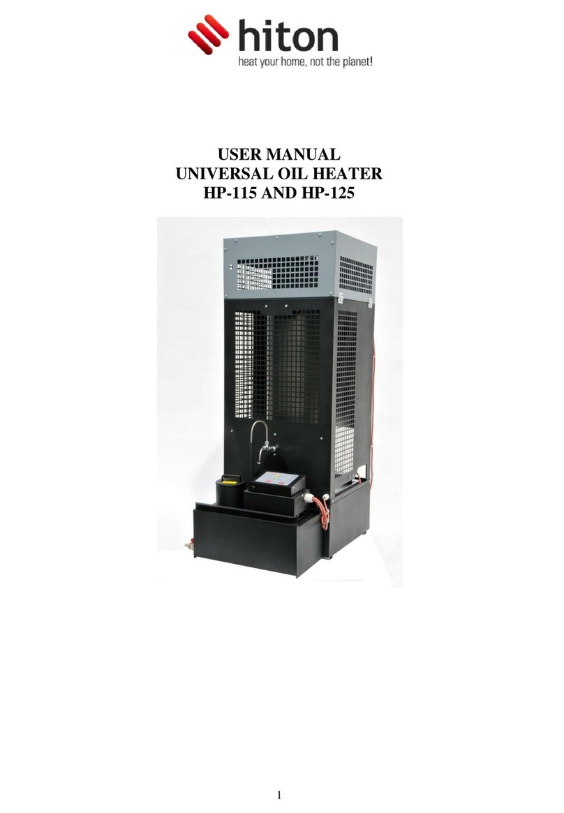
Hiton HP-115 User manual

HITON - heat your home, not the planet | 1
INSTRUKCJA OBSŁUGI NAGRZEWNICY NA OLEJ UNIWESALNY HP-115 I HP-125
USER MANUAL UNIVERSAL OIL HEATER HP-115 AND HP-125
LUFTERHITZER FÜR MB-ÖL HP-115/HP-125 BEDIENUNSANLEITUNG
ИНСТРУКЦИЯ ЭКСПЛУАТАЦИИ НАГРЕВАТЕЛЯ НА УНИВЕРСАЛЬНОМ МАСЛЕ
МОДЕЛИ HP-115 И HP-125
PL
ENG
DE
RU
H P -12 5
H P -115

2 |
PL Spis treści:
Rysunki techniczne
1. Przeznaczenie
2. Warunki środowiskowe składowania
3. Warunki środowiskowe użytkowania
4. Cechy charakterystyczne sterownika
5. Aspekty bezpieczeństwa
6. Konstrukcja urządzenia
7. Instalacja urządzenia
8. Opis działania urządzenia
9. Obsługa nagrzewnic
10. Naprawa usterek
DANE TECHNICZNE
DEKLARACJA ZGODNOŚCI WE
ENG Table of contents:
Figures and drawings
1. Use
2.Storage conditions
3. Conditions for use
4. Characteristics of the control panel
5. Safety measures
6. Construction of the heater
7. Installation
8. Functionning
9. How to operate the heater
10. Failures and remedies
TECHNICAL SPECIFICATIONS
EC DECLARATION OF CONFORMITY
DE Inhaltsverzeichnis:
Technischen Zeichnungen
1. Bestimmung
2. Umgebungsbedingungen der Lagerung
3. Umgebungsbedingungen der Nutzung
4. Eigenschaften des Steuerers
5. Sicherheitsaspekte
6. Einrichtungskonstruktion
7. Einrichtungsinstallation
8. Beschreibung der Einrichtungswirkung
9. Bedienung des Lufterhitzers
10. Fehlerbehebung
TECHNISCHEN DATEN
EGKONFORMITÄTSERKLÄRUNG
3
6
6
6
6
6
6
7
8
8
9
10
11
3
12
12
12
12
12
12
13
14
14
15
16
17
3
18
18
18
18
18
18
19
20
20
21
22
23
RU СОДЕРЖАНИЕ:
Технические рисунки
1. Предназначение
2. Условия складского хранения
3. Эксплуатационные условия
4. Характеристика контроллера
5. Безопасность
6. Конструкция устройства
7. Установка устройства
8. Описание работы устройства
9. Обслуживание нагревателя
10. Устранение неисправностей
ТЕХНИЧЕСКИЕ ДАННЫЕ
ДЕКЛАРАЦИЯ СООТВЕТСТВИЯ
3
24
24
24
24
24
25
25
26
27
28
29
30
www.hiton.pl

HITON - heat your home, not the planet | 3

4 |
MM
6
5
4
3
2
1
4
3
2
1
JP-1
JP-2
JP-3
3
2
1
T40
T100
OVF
KB
MP
MW
D1
D2
D3
D4
www.hiton.pl

HITON - heat your home, not the planet | 5
START
START STOP
min. 500 cm
Ø 150

6 |
Aby zapewnić właściwe użytko-
wanie i bezawaryjną eksploatację
pieca należy dokładnie zapoznać się
z niniejszą instrukcją.
1. Przeznaczenie
Nagrzewnica na olej uniwersalny typu
HP-115 i HP-125 przeznaczona jest
do ogrzewania pomieszczeń
przemysłowych bez systemu central-
nego ogrzewania (warsztaty, serwisy
samochodowe, hale przemysłowe,
magazyny, budynki inwentarskie,
piwnice, garaże, itp). Piec może
pracować na większości olejów
pochodzenia mineralnego
i roślinnego, takich jak oleje silnikowe,
opałowe, przekładniowe, hydraulicz-
ne, oleje typu HBO I, II, III o lepko-
ści kinematycznej max 6,00 mm²/s
w temperaturze 20ºC, temperaturze
punktu zapłonu nie niższej niż 40ºC
i gęstości nie mniejszej niż 0,94 g/cm³.
Ze względu na lokalne przepisy zaleca
się, aby w Polsce stosować olej napę-
dowy, olej opałowy lub biodiesel.
Nie stosować olejów transfor-
matorowych. Mogą one zawierać
substancje szkodliwe dla działania
pieca.
2. Warunki środowiskowe
składowania
Nagrzewnica na olej uniwersalny typu
HP-115 i HP-125 powinna być składo-
wana w następujących warunkach:
temperatura -20-85°C
wilgotność względna 5-85%
ciśnienie 800-
1200hPa
brak zapylenia V
środowisko wolne od
zanieczyszczeń chemicz-
nych
V
3. Warunki środowiskowe
użytkowania
Nagrzewnica na olej uniwersalny typu
HP-115 i HP-125 powinna być użytko-
wana w następujących warunkach:
temperatura 0-30°C
wilgotność względna 5-85%
ciśnienie 800-
1200hPa
stopień ochrony przed
wpływem środowiska
IP20
dobra wentylacja ogrze-
wanego pomieszczenia
V
4. Cechy charakterystyczne
sterownika
• możliwość regulacji mocy pieca
w zakresie 15 i 22 kW (HP-115)
oraz 22 i 30 kW (HP-125),
• zabezpieczenie przed przegrzaniem
paleniska,
• zabezpieczenie przed przelaniem
oleju w palenisku,
• automatyczne zachowanie nastaw
przy zaniku napięcia zasilającego.
5. Aspekty bezpieczeństwa
Nagrzewnica na olej uniwersalny
HP-115 i HP-125 jest zasilana z sie-
ci prądu przemiennego 230V/50Hz.
Na obudowie modułu sterującego
zainstalowano bezpiecznik z wkładką
topikową (1A, 250V). Wymiana tego
bezpiecznika powinna być wykonywa-
na bezwarunkowo przy wyłączonym
zasilaniu zewnętrznym układu (230V
AC, 50Hz).
Nagrzewnica na olej uniwersalny
typu HP-115 i HP-125 jest wyposażona
w dwa czujniki bimetaliczne zapew-
niające bezpieczną i ekonomiczną
pracę urządzenia.
Czujnik bimetaliczny [p k t 4 niniejszej
instrukcji] umieszczony na komorze
spalania reaguje zwarciem styków,
gdy temperatura paleniska przekro-
czy 40°C i rozwarciem styków, gdy
temperatura spadnie poniżej 35°C.
W sytuacjach alarmowych (przegrza-
nie, przelanie oleju) procesor spraw-
dza sygnał z czujnika bimetalicznego
[p k t I / 4] i wyłacza wentylator na-
wiewowy gdy temperatura paleniska
spada do temperatury ponizej 35°C.
Drugi czujnik bimetaliczny [p k t I / 1]
umieszczony jest w pobliżu wentylato-
ra nawiewowego, a jego temperatura
progowa wynosi 90°C. Rozwarcie
jego styków w wyniku przekroczenia
temperatury progowej powoduje na-
tychmiastowe przejście pieca w tryb
Przegrzanie.
Nagrzewnica wyposazona jest także
w wagowy czujnik umieszczony pod
komorą spalania [p k t I / 4].
Napełnienie miseczki powoduje
natychmiastowe przejście pieca
w tryb Przelanie.
Połączenie panelu sterującego pieca
z innymi elementami systemu (czujni-
ki, pompa, wentylator) jest wykony-
wane fabrycznie . W trakcie normalnej
eksploatacji, ze względu na bezpie-
czeństwo obsługi, nie dopuszcza się
do jakiejkolwiek ingerencji w osłoniętą
i zaplombowaną część sterownika
pieca oraz naruszanie integralności
przewodów. Jakiekolwiek działanie
nieuprawnionej osoby grozi poraże-
niem prądem elektrycznym (230V AC,
50Hz) oraz poparzeniem.
6. Konstrukcja urządzenia
Rys. l. Budowa nagrzewnicy:
Oznaczenia
Zabezpieczenie przed prze-
grzaniem (HP-125)
Pokrywa komory paleniska
Przewód podawania oleju
Termostat przy komorze
spalania
Pompa i sterownik
Zbiornik paliwa
Cylinder blaszny
Pierścień blaszany
Pierścień z drutu
Komora paleniska
Misa paleniska
Podstawa paleniska
Otwór przelewowy
Zabezpieczenie przelewowe
PL
www.hiton.pl

HITON - heat your home, not the planet | 7
Rys.2. Schemat blokowy nagrzewnicy
na olej uniwersalny HP-115 i HP-125.
T40 bimetaliczny czujnik
temperatury paleniska
T100 bimetaliczny czujnik
bezpieczeństwa ( STB)
OVF bezpiecznik przelewowy
MP pompa (moc 48W [230V AC,
50Hz])
MW wentylator (moc 35W [230V
AC, 50Hz], wydajność
600 m³/h (HP-115)
i l000 m³/h (HP-125)
KB klawiatura
D1 wskaźnik przegrzania pieca
D2 wskaźnik przepełnienia
zbiornika przelewowego
D3 wskaźnik prędkości
obrotowej silnika pompy
D4 wskaźnik włączenia
i wyłączenia pieca
moduł sterownika
Rys.3. Sterownik pieca
7. Instalacja urządzenia
Podczas instalowania urządzenia
należy spełnić wszelkie lokalne
przepisy, włączając w to przepisy
odnoszące się do norm krajowych
i norm europejskich.
1. Ustawić piec na płaskim
betonowym podłożu.
2. Wypoziomować urządzenie.
Aby sprawdzić czy nagrzewnica jest
wypoziomowana, umieścić misę
paleniska w dolnej części komory
spalania i wylać na nią niewielką ilość
oleju napędowego. Olej powinien
rozlać się dokładnie na środku misy.
3. Zamontować stabilizator ciągu na
rurze wychodzącej z komory spalania,
by zapewnić w jej wnętrzu stabilny
ciąg w czasie pracy nagrzewnicy.
4. Dla zapewnienia optymalnego
ciągu zainstalować przynajmniej 6-cio
metrową gładką, odporną na wysoką
temperaturę pionową rurę kominową
(nie aluminiową).
5. Sprawdzić szczelność wszystkich
połączeń, w razie potrzeby uszczelnić
taśmą izolacyjną.
6. Upewnić się, że misa spalania jest
umieszczona centralnie w komorze
spalania.
7. Umieścić górny pierścień we wnę-
trzu komory spalania wypustką po
środku pierścienia w górę i zamonto-
wać na nim cylinder dopalacza (rura
gorącego powietrza).
8. Sprawdzić napięcie sieciowe
(220-240V/50Hz) i podłączyć piec do
zasilania. Wentylator i pompa nie
powinny się uruchomić, ponieważ piec
nie jest jeszcze włączony i ciepło nie
zostało wyprodukowane
9. Zachować bezpieczną odległość od
materiałów łatwopalnych.
Wentylatory wyciągowe po-
wietrza pracujące w tym samym
pomieszczeniu lub przestrzeni,
co urządzenie mogą wprowadzić
zakłócenia.
Montaż przewodu kominowego
Dla zapewnienia prawidłowego
spalania konieczna jest prawidłowo
wykonana instalacja kominowa.
Przy jej wykonaniu należy przestrze-
gać poniższych zaleceń:
Minimalna średnica rury - 150mm.
Sprawdzić szczelność połączeń mię-
dzy elementami komina.
Minimalna wysokość komina - 6m.
Zewnetrzny odcinek komina powinien
byc izolowany (podwójna scianka).
Wiatr powinien swobodnie owiewać
wylot komina ze wszystkich kierun-
ków (koniec rury kominowej powinien
się znajdować powyżej szczytu dachu).
Jeśli to możliwe, wszystkie odcinki
komina powinny być pionowe - należy
unikać odcinków poziomych, a tak-
że zagięć rury kominowej. Jeśli są
konieczne (np. dwa zagięcia w przy-
padku prowadzenia rury przez ścianę
lub okno) wówczas maksymalny kąt
załamania wynosi 45°, minimalna
wysokość komina powinna być zwięk-
szona do 7m.
Minimalny ciąg kominowy 16Pa przy
nominalnej mocy cieplnej.
Urządzenia nie można przyłączyć do
systemu wspólnego odprowadzenia
spalin.
UWAGA
Montując system odprowadze-
nia spalin zaleca się unikanie po-
ziomych odcinków rury kominowej.
W celu zapewnienia swobodnego
odpływu gazów, kąt ewentualnego
zgięcia rury nie powinien być więk-
szy niż 45°. Wylot komina musi być
wyżej niż wierzchołek dachu.
Miejsca, w których przeprowa-
dzone są rury przez sufit, ściany lub
dach, muszą być izolowane w celu
uniknięcia zagrożenia pożarowego.
Zalecane jest używanie dwuwar-
stwowej izolowanej rury kominowej
wszędzie tam, gdzie istnieje moż-
liwość kontaktu dotykowego oraz
na zewnątrz budynku, by zapewnić
stały dobry ciąg i zapobiec kon-
densacji. Nie umieszczać żadnych
materiałów w pobliżu pieca, nawet
niepalnych. Zapewnić stały dostęp
powietrza, niezbędnego dla prawi-
dłowego procesu spalania.
Rys.4. Instalacja kominowa
PL
Oznaczenia:
termostat paleniska
termostat bezpieczeństwa
(STB)
bezpiecznik przelewowy
wentylator
pompa
230V, 50Hz
sterownik HP-125

8 |
8. Opis działania urządzenia
Panel sterowania
Sterownik pieca na olej uniwersalny
typu HP-115 i HP-125 i wyposażony
jest w cztery przyciski pozwalające
użytkownikowi na sterowanie pracą
nagrzewnicy oraz cztery diody sygna-
lizujące stany pracy urządzenia.
Rys.5. Widok panelu przedniego modułu
sterującego nagrzewnicy na olej uniwer-
salny.
Oznaczenia
Regulacja wydajności pieca
Włącznik pieca
Wyłącznik pieca
Wskaźnik przegrzania pieca
(termostat STB)
Wskaźnik przepełnienia
miseczki przelewowej
Wskaźnik pracy pompy
Wskaźnik gotowości pieca
do pracy
Diody LED
Pracę urządzenia charakteryzują
następujące stany:
St o p urządzenie gotowe
do uruchomienia
Ro z p a l a n i e wstępna faza
pracy urządzenia
pR a c a właściwa praca urzą-
dzenia
Wy g a S z a n i e wyłączanie
urządzenia
pR z e g R z a n i e wyłączenie awaryjne
pR z e l a n i e
z b i o R n i k a
wyłączenie awaryjne
Proces wytwarzania ciepła odbywa
się poprzez spalanie gazu wytwarza-
nego przez podgrzany do wysokiej
temperatury olej. W momencie podłą-
czenia urządzenia do sieci zasilającej
znajduje się ono w stanie gotowości
(Stop) i ciepło nie jest wytwarzane,
nie pracuje ani wentylator ani pompa.
Naciśnięcie przycisku Start powoduje
zapalenie zielonej diody i przejście
pieca w fazę rozpalania. Po rozgrza-
niu paleniska do temperatury 40°
C następuje zwarcie styków termo-
statu umieszczonego przy komorze
spalania i włączenie pompy podającej
olej oraz wentylatora nawiewowego
Jest to sygnalizowane zapaleniem
żółtej diody na panelu sterowania. Ze
względu na mniejsze zapotrzebowanie
na olej przy nierozgrzanym palenisku
przez przynajmniej 30 minut urzą-
dzenie powinno pracować na pierw-
szym biegu (na pulpicie zaznaczono
znakiem „-„ dioda żółta świeci się
z niską jasnością).W tym czasie pom-
pa do paleniska podaje ok. 1,25 kg/h
(HP-115) i 1,85 kg/h (HP-125) oleju. Po
trzydziestu min, pracy można włączyć
drugi bieg (na pulpicie zaznaczono
znakiem „+” dioda żółta świeci się
większą jasnością. W czasie pracy na
drugim biegu do paleniska jest poda-
wane ok.1,85 kg/h (HP-115) i 2,55 kg/h
(HP-125) oleju.
Wyłączenie nagrzewnicy odbywa się
poprzez wciśnięcie przycisku Stop na
panelu sterowania. W tym momencie
następuje wyłączenie pompy (gaśnie
żółta i zielona dioda na panelu stero-
wania). Wentylator wyciągowy działa
dopóki temperatura paleniska nie
spadnie poniżej 35°C (Wygaszanie).
Po osiągnięciu temperatury niższej niż
35°C piec powraca do fazy Stop.
Wyłączenie pieca może wystąpić
automatycznie w wyniku przegrzania
komory spalania lub przelania.
Sygnał przegrzania jest generowany
przez bimetaliczny czujnik umieszczo-
ny w pobliżu wentylatora. Rozwarcie
styków sygnalizuje przekroczenie pro-
gowej wartości temperatury. Układ
sterowania wyłącza pompę (gaśnie
wskaźnik pracy pompy żółta dioda).
Stan przegrzania sygnalizowany jest
zapaleniem czerwonej diody na pane-
lu sterowania. Wentylator wyciągowy
działa dopóki temperatura paleniska
nie spadnie poniżej 35°C. Po osiągnię-
ciu temperatury niższej niż 35°C, piec
powraca do fazy Stop.
Po przejściu do fazy Stop (a nawet po
wyłączeniu i ponownym włączeniu
zasilania) sygnalizacja przegrzania nie
gaśnie. Umożliwia to użytkownikowi
ustalenie przyczyny wyłączenia pieca.
Aby zresetować sygnalizację prze-
grzania i powrócić do normalnej pracy
należy odczekać do momentu wychło-
dzenia pieca (wyłączenia wentylatora)
i wcisnąć przycisk umieszczony na
obudowie czujnika bimetalicznego.
Następnie nacisnąć przycisk Start, co
spowoduje zgaśnięcie diody sygna-
lizującej przegrzanie. Piec można
ponownie uruchomić.
Sygnał przelania jest generowany
przez mechaniczny czujnik umiesz-
czony pod zbiornikiem przelewo-
wym. Rozwarcie styków sygnalizuje
przepełnienie zbiornika. Jednocześnie
wyłącza się pompa - gaśnie wskaźnik
pracy pompy (żółta dioda), a zapala się
odpowiednia czerwona dioda ozna-
czająca przepełnienie. Wentylator
wyciągowy działa dopóki temperatura
paleniska nie spadnie poniżej 35°C.
Po osiągnięciu temperatury niższej
niż 35°C piec powraca do fazy Stop.
Należy opróżnić zbiornik przelewowy,
a następnie nacisnąć przycisk Start,
co spowoduje zgaśnięcie diody sygna-
lizujące przelanie (czerwonej). Piec
można ponownie uruchomić.
9. Obsługa nagrzewnic
UWAGA
Nie wolno dolewać oleju do
paleniska i rozpałać, gdy komora
lub misa paleniska jest jeszcze
gorąca!!! Zawsze odczekać do cał-
kowitego schłodzenia misy palnika.
Nieprzestrzeganie powyższego
zalecenia grozi niekontrolowanym
zapłonem oparów oleju i poparze-
niem!!!
Uruchomienie urządzenia
Po uruchomieniu nagrzewnica
wchodzi w odpowiednie stany pracy
w zależności od ustawień wprowadzo-
nych przez użytkownika i informacji
otrzymywanych przez czujniki dołą-
czone do układu sterownika.
W razie potrzeby odprowadzić wodę ze
zbiornika paliwa i napełnić go olejem
przepracowanym.
Włożyć wtyczkę kabla zasilającego do
gniazda sieciowego (230V/50Hz).
Odchylić górną cześć obudowy na-
grzewnicy i zdjąć pokrywę komory
spalania, następnie wyjąć cylinder
i pierścień (w razie konieczności
dokładnie wyczyścić misę spalania
i podstawę, na której jest ona umiesz-
czona, a także całą komorę spalania
wraz z tuleją i pierścieniem).
Sprawdzić czy misa paleniska jest
chłodna i czysta, następnie wylać na
nią ok. 250 ml oleju opałowego lub
napędowego.
Zapalić olej używając w tym celu
zgniecionego w kulkę kawałka papie-
ru, który należy podpalić a następnie
wrzucić na misę paleniska.
PL
www.hiton.pl

HITON - heat your home, not the planet | 9
Zamontować pierścień i cylinder,
założyć pokrywę komory spalania,
zamknąć górną część obudowy na-
grzewnicy.
Nacisnąć przycisk Start na pane-
lu sterowania (zaświeci się zielona
dioda).
Po około 10-15 min, w zależności od
temperatury pomieszczenia, włączy
się pompa paliwa oraz wentylator
i jednocześnie zapali się żółta dioda
pracy pompy, piec zacznie pracować
na pierwszym biegu ze zmniejszona
wydajnością:
15kW, spalanie 1,25kg/h – HP-115
22kW, spalanie 1,85 kg/h – HP-125
Drugi bieg ze zwiększoną wydajnością
uruchomia się poprzez przyciśnięcie
znaku +na panelu sterowania:
22kW, spalanie1,85 kg/h – HP-115
30kW, spalanie 2,55kg/g – HP-125
Każde naciśnięcie przycisku Stop
i ponowne uruchomienie przyciskiem
Start w czasie jego pracy powoduje
ponowne wprowadzenie pieca w fazę
rozpalania.
Wyłączenie urządzenia
Na panelu sterowania nacisnąć
przycisk Stop (gaśnie żółta), pompa
przestaje podawać paliwo na misę
spalania, wentylator pracuje do mo-
mentu wychłodzenia pieca.
Nie wolno odłączać urządzenia
od zasilania, gdy wentylator pra-
cuje. Należy zaczekać do momentu
schłodzenia pieca. Wyłączenie pieca
następuje automatycznie. Należy
pamiętać, że po wyłączeniu się
urządzenia żeliwna misa utrzymuje
wyższą temperaturę jeszcze przez
pewien czas (w zależności od tem-
peratury otoczenia) i nie można
ponownie odpalać pieca dopóki nie
wystygnie.
Konserwacja
Nagrzewnica wymaga niewielu zabie-
gów konserwacyjnych. Przestrzeganie
zaleceń producenta w tym zakresie
zapewni bezawaryjną i bezpieczną
prace urządzenia
Codziennie wyczyścić misę paleniska,
i elementy komory spalania (cylinder,
pierścień i pokrywę).
Sprawdzić drożność przewodu prze-
lewowego (przewód gumowy w dolnej
części komory spalania, bezpośrednio
nad zbiornikiem paliwowym), w razie
potrzeby przeczyścić.
Przynajmniej raz w tygodniu czyścić
podstawę paleniska w komorze spala-
nia (element pod misą paleniska).
Sprawdzać czy otwory wlotu po-
wietrza w dolnej oraz górnej części
komory spalania nie są zasłonięte.
Raz w tygodniu czyścić przewód poda-
wania oleju na misę paleniska. Mak-
symalny czas pracy bez czyszczenia
misy paleniska wynosi ok. 7-14 godzin
(w zależności od oleju stosowanego do
spalania).
W ciągu sezonu grzewczego czyścić
zbiornik paliwa i filtr pompy olejowej.
Jeżeli piec będzie wyłączony przez
dłuższy okres, należy starannie
oczyścić komorę spalania i zbiornik
i zabezpieczyć je przed korozją powle-
kając cienką warstwą oleju.
Zaleca się wykonywanie sezo-
nowych przeglądów w autoryzowa-
nym serwisie.
10. Naprawa usterek
W przypadku awarii urządzenia
poniższa lista może pomóc w zlokali-
zowaniu usterki. Na ogół jej usunięcie
jest proste. Najczęstsze problemy
wymienione są poniżej. Cyfry ozna-
czają możliwe przyczyny. Kolejność
cyfr wyraża prawdopodobieństwo
wystąpienia usterki.
UWAGA
Przed przystąpieniem do jakich-
kolwiek czynności wyjąć wtyczkę
z gniazdka.
PL

10 |
HP115 HP125
Minimalna wydajność cieplna kW 15 22
Maksymalna wydajność cieplna kW 22 30
Minimalne zużycie oleju kg/h 1,25 1,85
Maksymalne zużycie oleju kg/h 1,85 2,55
Przepływ ogrzanego powietrza m3 600 1000
Zasilanie elektryczne V/Hz 230/50 230/50
Pobór prądu A 0,6 0,6
Średnica rury kominowej mm 150 150
Szerokość cm 54 85
Wysokość cm 137 137
Długość cm 75 54
Waga kg 90 90
DANE TECHNICZNE
PL
Nr PRZYCZYNA SPOSÓB USUNIĘCIA
1Brak zasilania elektrycznego. Sprawdzić, czy wtyczka jest w gniazdku i sprawdzić bezpieczniki
2Woda lub osad w zbiorniku. Wyczyścić zbiornik i filtr
3Silnik pompy nie włącza się Sprawdzić STB i zabezpieczenie przelewowe
4Silnik i pompa nie działają Paliwo jest zbyt gęste lub zbyt zimne. Rozcieńczyć olejem napędowym
Sprawdzić termostat kontroli pracy pompy i w razie potrzeby wymienić.
Sprawdzić silnik i zobaczyć, czy pompa nie jest zabrudzona wewnątrz.
Sprawdzić STB i zabezpieczenie przelewowe
5Przewód paliwa jest zatkany, olej wraca do
zbiornika przewodem powrotnym
Wyczyścić przewód paliwa lub w razie potrzeby - wymienić
6Termostat kontroli pracy pompy nie osiągnął
odpowiedniej temperatury
Odczekać, aż piec ostygnie i uruchomić ponownie
Wymienić termostat
7Zabezpieczenie przelewowe jest pełne Wyczyścić
8Termostat bezpieczeństwa (STB) nie działa pra-
widłowo lub nie działa w ogóle
Zresetować termostat
Wymienić
9Niewystarczający dopływ powietrza spalania Wyczyścić otwory komory paleniskowej
Sprawdzić prawidłowe działanie wentylatora
10 Nieprawidłowy ciąg Sprawdzić, czy rura kominowa jest zamontowana zgodnie z zaleceniami pt.
„Montaż przewodu kominowego”
Sprawdzić szczelność systemu kominowego
W razie potrzeby wyczyścić
11 Ciąg kominowy jest zbyt mocny lub zbyt zmienny Zamontować stabilizator ciągu i wyregulować go na min. 2 mm W.C. (16 Pa).
12 Ciąg kominowy jest zbyt słaby Sprawdzić wszystkie połączenia
Zmniejszyć liczbę zgięć
Wydłużyć komin
Zaizolować rurę kominową na zewnątrz budynku
Przejrzeć wszelkie informacje na temat przewodu kominowego w instrukcji.
USTERKA PRZYCZYNA
Pompa nie uruchamia się i kontrolka pracy pompy nie zapala się 6 - 3 - 7
Płomień gaśnie a pompa nadal pracuje 2 - 5 - 9 - 10 - 12
Komora spalania huczy 10 - 11 - 12
W komorze spalania i w kominie pojawia się sadza 8 - 9 - 10 - 11 - 12
Na płycie spalania pozostaje niespalony olej lub zbyt dużo oleju napędowego przy rozruchu 8 - 9 - 11 - 12
www.hiton.pl

HITON - heat your home, not the planet | 11
PL
DEKLARACJA ZGODNOŚCI WE
Producent: ABIZA
Adres: 05-825 Grodzisk Mazowiecki
Opypy, ul.Jemiołowa 2, Polska
Produkt: Marka: / Marke: HP
Model: / Modell: HP-115
Niniejszym deklarujemy z całą odpowiedzialnością,
że wymienione produkty spełniają wymagania
bezpieczeństwa Dyrektyw Europejskich.
Dyrektywy: 2006/95/WE
Dyrektywą niskonapięciową (LVD)
2004/108/WE
Dyrektywą Kompatybilności
Elektromagnetycznej (EMC)
89/106/WE
Dyrektywą Wyroby Budowlane
Zastosowane normy:
PN-EN 1, PN-EN 1:2001/A1, PN-EN 60335-1, PN-
EN 60335-1-102, PN-EN 55014-1:2007, PN-EN
55014-2:1999+A1:2004+IS1:2007, PN-EN 55014-
1:2004, PN-EN 61000-3-2004+ A2:2005, PN-EN
61000-3-3:1997+A1:2005+A2:2006, PN-EN 55014-1,
PN-EN 61000-4-2: 1999+A2:2003, PN-EN 61000-4-4:2005,
PN-EN 61000-4-6:2007, PN-EN 61000-4-5:2006, PN-EN
61000-4-11:2007, PN-EN 61000-3-3:1997+A1:2002(U)
Oznaczenie CE zostało nadane w: 2008 r.
Deklaracja wydana przez: ABIZA
Miejscowość, data: Opypy, 12.08.2008
Andrzej Białous
właściciel firmy
Podpis osoby upoważnionej
DEKLARACJA ZGODNOŚCI WE
Producent: ABIZA
Adres: 05-825 Grodzisk Mazowiecki
Opypy, ul.Jemiołowa 2, Polska
Produkt: Marka: / Marke: HP
Model: / Modell: HP-125
Niniejszym deklarujemy z całą odpowiedzialnością,
że wymienione produkty spełniają wymagania
bezpieczeństwa Dyrektyw Europejskich.
Dyrektywy: 2006/95/WE
Dyrektywą niskonapięciową (LVD)
2004/108/WE
Dyrektywą Kompatybilności
Elektromagnetycznej (EMC)
89/106/WE
Dyrektywą Wyroby Budowlane
Zastosowane normy:
PN-EN 1, PN-EN 1:2001/A1, PN-EN 60335-1, PN-
EN 60335-1-102, PN-EN 55014-1:2007, PN-EN
55014-2:1999+A1:2004+IS1:2007, PN-EN 55014-
1:2004, PN-EN 61000-3-2004+ A2:2005, PN-EN
61000-3-3:1997+A1:2005+A2:2006, PN-EN 55014-1,
PN-EN 61000-4-2: 1999+A2:2003, PN-EN 61000-4-4:2005,
PN-EN 61000-4-6:2007, PN-EN 61000-4-5:2006, PN-EN
61000-4-11:2007, PN-EN 61000-3-3:1997+A1:2002(U)
Oznaczenie CE zostało nadane w: 2008 r.
Deklaracja wydana przez: ABIZA
Miejscowość, data: Opypy, 12.08.2008
Andrzej Białous
właściciel firmy
Podpis osoby upoważnionej
ABIZA
Polska, 05-825 Grodzisk Mazowiecki
Opypy, ul.Jemiołowa 2
ABIZA
Polska, 05-825 Grodzisk Mazowiecki
Opypy, ul.Jemiołowa 2
08
EN 1
Typ: HP 115
Odległość do materiałów palnych: 140 cm
Klasa urządzenia: klasa 5
Moc cieplna: 22 kW
Rodzaj paliwa: olej opałowy
Bezpieczeństwo elektryczne: spełnione
08
EN 1
Typ: HP 125
Odległość do materiałów palnych: 140 cm
Klasa urządzenia: klasa 5
Moc cieplna: 30 kW
Rodzaj paliwa: olej opałowy
Bezpieczeństwo elektryczne: spełnione

12 |
Please read the following in-
struction carefully in order to make
sure that the heater is used proper-
ly and does not cause malfunction.
1. Use
HP-115 and HP-125 universal oil
heater are suitable for heating big
size buildings without central heating
(shops, service stations, industrial
buildings, warehouses, inventory buil-
dings, basements, garages, etc.) The
heater runs on most oils of mineral
and plant origin, such as motor oils,
heating oil, gear oils, hydraulic oils,
HBO I, II, III oils with maximum kine-
matic viscosity 6.00 mm²/s at a tem-
perature of 20ºC and maximum igni-
tion temperature not lower than40ºC
and density above 0.94 g/cm³.
In light of binding regulations in some
countries it is recommended that
diesel oil, heating oil or biodiesel be
used.
Not to be used with transformer
(insulating) oils. They may contain
substances that can damage the
heater
2. Storage conditions:
HP-115 and HP-125 universal oil he-
aters should be stored in the following
conditions:
temperature -20-85°C
relative humidity 5-85%
pressure 800-
1200hPa
free of dust V
free of chemical
pollutants
V
3. Conditions for use:
HP-115 and HP-125 universal oil
heaters should be operated under the
following conditions:
temperature 0-30°C
relative humidity 5-85%
pressure 800-
1200hPa
environmental impact
protection
IP20
appropriate ventilation
of heated area
V
4. Characteristics
of the control panel:
• the heater may be regulated
and set at 15 and 22kW (HP-115)
or 22 and 30 kW (HP-125),
• protection against overheating
the burner,
• protection against overow of oil
in the burner,
• automatic retaining of previous
settings in case of power failure,
5. Safety measures:
HP-115/HP-125 universal oil heater is
connected to 230V/50Hz alternating
current network. A fuse element (1A,
250V) was installed in the casing of
the control panel. The fuse should
always be replaced with the power
(230V/50Hz) switched off.
HP-115 /HP-125 universal oil heater is
equipped with two bimetallic sensors
assuring safe and effective functio-
ning of the device.
Bimetallic sensor (see figure 4 of the
instruction) in the burner triggers
reaction in form of clenching contacts
when the temperature in burner rises
above 40°C and opening of contacts
when the temperature falls below
35°C. In cases such as overheating
or oil overow, processor controls
the signal from the bimetallic sensor
and activates ventilating fan until the
burner cools down to the temperature
below 35°C.
Second bimetallic sensor (see figure
1 of the instruction) is installed next
to the blower fan with threshold
temperature set at 90°C. Clenching
of contacts, when threshold tempe-
rature is exceeded, causes that the
burner immediately switches into the
overheating mode (see point. 8 of the
instruction).
The heater is also equipped with we-
igh sensor placed under the overow
tank (the so-called overow fuse).
When the tank is filled, the heater im-
mediately switches into the overow
mode (see point 8 of the instruction).
The control panel of the heater is fac-
tory-connected with other elements
of the system (such as sensors, pump,
and fan) and it is a safety requirement
that during regular use there be no
interference with covered and sealed
part of the control panel as well as
integrity of wiring. Any interference
of unauthorized person may cause an
electric shock (230V/50Hz) and burns.
6. Construction of theater
Figure 1:
Terms:
Overheating control
Burner lid
Oil feed line
Burner chamber thermostat
Pump and control panel
Fuel tank
Cylinder
Ring
Wire ring
Combustion chamber
Vaporising pan
Combustion chamber basin
ow gauge
overow fuse
ENG
www.hiton.eu

HITON - heat your home, not the planet | 13
Figure 2: Diagram of HP-115 and HP-125
universal oil heater
T40 Bimetallic sensor
of burner’s temperature
T100 Bimetallic thermostat
(STB)
OVF Overow fuse
MP Pump (48W [230V AC,
50Hz])
MW Fan (35W [230V/50Hz],
capacity 600 m³/h (HP-
115), capacity l000 m³/h
(HP-125)
KB Keyboard
D1 Heater overheating
indicator
D2 Overow tank indicator
D3 Pump engine rotational
speed indicator
D4 Heater turn on/off indicator
Figure 3: Control panel
7. Installation
When installing the heater, all local
regulations are to be complied with,
including regulations referring to
national norms.
1. Place the heater on at surface
made of concrete.
2. Level the device in order to check if
the heater is levelled correctly, place
the vaporising pan in the lower part of
the combustion chamber and pour a
small amount (approximately 250ml)
of diesel oil onto it. The oil should stay
exactly in the middle of the pan.
3. Install current stabilizer (valve) on
the combustion chamber’s outlet pipe
in order to maintain constant draught
inside the pipe during the operation.
4. Install at least six meters long,
smooth and temperature resistant
horizontal ue (not aluminium ue) in
order to provide optimum draught.
5. Check tightness of all joints, if ne-
cessary use the insulation tape.
6. Make sure that the vaporising pan
is placed centrally in the combustion
chamber.
7. Place the upper ring inside the
combustion chamber with ange
facing upwards and install the hot air
pipe.
8. Check the power (220-240V/50Hz)
and connect the heater to the power
outlet. Neither fan nor the pump sho-
uld become active because the burner
has not been switched on and the heat
has not been produced yet.
9. The heater should be placed away
from combustible materials
Ventilation fans working in the
same room or area as the heater
may cause disruptions.
Fitting the flue
To ensure the right combustion appro-
priate tting of the ue in necessary.
The following recommendations sho-
uld be adhered to when tting the ue:
Minimum ue diameter - 150mm.
Check tightness of joints between ue
elements.
Minimum ue height- 6m.
The inside of the ue should be insu-
lated (double skinned).
The tube should be in free air (the
tip of the ue should be above the
rooftop).
If possible, all sections of the ue sho-
uld be in vertical position, horizontal
positioning should be avoided, as well
as bending of the ue. However, if it is
necessary to bend a ue (for exam-
ple a ue bent in two places when it
runs through a wall or a window), the
maximum angle is 45° with minimum
height of the ue increased to 7m.
Minimum ue draught of 16Pa with
nominal heat.
The device cannot be connected to the
joint combustion outlet system.
CAUTION!
When installing the combustion
outlet system it is recommended
not to place ues in horizontal
position. In order to guarantee free
movement of gases, the angle of
ue should not exceed 45°. The ue
outlet must be above the rooftop.
Flues running through the
ceiling, walls or the roof, must be
insulated in order to prevent fire.
It is recommended to use double
skinned ue in places where the
ue is likely to be touched by the
general public and on the outside of
the building in order to guarantee
good draught and prevent con-
densation. No materials should be
placed close to the heater, even
incombustible ones. Free air move-
ment should be provided to assure
proper combustion process.
Figure 4: Fitting the flue
ENG
Terms:
burner thermostat
STB bimetallic thermostat
overow fuse
fan
pump
230V, 50 Hz
control panel HP-125

14 |
8. Functionning
Control panel
The control panel of HP-115and HP-
125 universal oil heater is equipped
with four buttons enabling the user to
control the operation of the heater and
four diodes signalling the operating
modes of the device.
Figure 5: ..
Terms:
heater output control
on switch
off switch
overheat control STB
Vaporising pan overow
control
pump control
heater readiness for use
LED diodes
The device operates in the following
modes:
St o p Device ready for use
He a t i n g u p Preliminary operating
phase
ino p e R a t i o n The device is working
normally
SH u t t i n g o f f The device is shutting
off
ov e R H e a t i n g Contingency switching
off
ta n k o v e R -
f l o W
Contingency switching
off
The heat is produced during gas com-
bustion when oil is heated up to a high
temperature. When connecting the
heater to power network, the device
is in stand-by mode (Stop). Heat is not
produced and fan and pump are not
working. Pressing the Start button
triggers the green diode to turn on
and the heater goes into the heating
up mode. Once the burner is heated
up to 40°C the joints of thermostat
placed next to combustion chamber
clutch activating the oil inlet pipe and
blower fan; these are signalled by the
yellow diode on the control panel. At
the beginning smaller amount of oil
is required for at least 30 minutes,
when the burner has not been heated
up, and the device should work on its
first gear (on the screen displayed as
“-“ – yellow diode is dim). During this
time, the pump feeds the combustion
chamber with approximately 1.25
kg/h (HP-115) or 1.85 kg/h (HP-125) of
oil. After 30 minutes, we may shift to
second gear (on the screen displayed
as “+” – yellow diode is bright), during
which time the chamber is supplied
with approximately 1.85 kg/h (H-P115)
or 2.55 kg/h (HP-125) of oil.
The heater is switched off by pres-
sing Stop button on the control panel.
The pump is switched off (yellow and
green diodes on the control panel go
off). Ventilation fan works until the
temperature in the chamber falls
below 35°C (Shutting off). After the
temperature in the chamber has fal-
len below 35°C, the burner switches
to the Stop mode.
The heater may switch off automa-
tically if the combustion chamber is
overheated or in case of overow.
Overheating signal is generated by the
bimetallic thermostat located close
to the fan. Opening of joints signals
that the threshold temperature has
been exceeded. Control system turns
the pump off (pump indicator, yellow
diode, goes off) and overheating is
signalled when a red diode on the
control panel switches on. Ventilation
fan works until the temperature in the
chamber falls below 35°C. After the
temperature in the chamber has fal-
len below 35°C, the burner switches
to the Stop mode
Once the heater is in the Stop mode
(and even after switching off and sub-
sequently switching on the device) the
overheating signal is on. This enables
the user to find out what caused the
heater to stop.
In order to reset the overheating
signal and regain normal functioning
of the device, one should wait until the
burner cools off completely (ventila-
tion fan switches off) and press the
button on the casing of bimetallic
thermostat. Then press Start button,
which will cause the overheating
diode to go off. The heater may be
switched on again.
Overow signal is generated by a
mechanic sensor located underneath
the overow tank. Opening of joints
signals that the tank is overow. At
the same time the pump is switched
off, the pump indicator goes off, and
the red diode signalling overow swit-
ches on. Ventilation fan works until
the temperature in the chamber falls
below 35°C. After the temperature in
the chamber has fallen below 35°C,
the burner switches to the Stop mode.
The overow tank is to be emptied,
and then Start button should be pres-
sed, which will cause the red overow
diode to go off. The heater may be
switched on again.
9. How to operate the heater
CAUTION!
Oil must not be poured into the
burner if
The chamber or the pan is still
hot!!! Always wait until the burner
has cooled down. Non-compliance
with the above warning may cause
explosion of oil vapours and burns!!!
How to operate the device
Once engaged, the heater switches to
desired modes depending on settings
chosen by the user and information
transmitted by sensors connected to
the control panel.
If necessary, water may be poured
from the tank and replaced with used
oil.
Plug into the power socket
(230V/50Hz).
Pull the upper part of the cover aside
and take the burner lid off, take the
cylinder and the ring out (if necessary,
clean thoroughly the vaporising pan
and its base, the burner, cylinder and
ring). Check if the vaporising pan is
cool and clean, and then pour appro-
ximately 250 ml of heating or diesel oil
onto it.
Light oil using a piece of scrunched up
paper that needs to be put on fire and
thrown onto the vaporising pan.
Install ring and cylinder, put the bur-
ner lid back on, close the upper part
of burner’s casing.
Press Start button on the control
panel (green diode turns on)
After approx. 10-15 minutes, depen-
ding on the temperature in the room,
the fuel pump and ventilation fan will
start and the yellow pump diode will
www.hiton.eu
ENG

HITON - heat your home, not the planet | 15
turn on at the same time. The heater
starts working on the lowest gear
with lower performance and can
continue operating in this mode on a
continuous basis:
15 kW; 1.25 kg/h – HP-115 and
22 kW; 1.85 kg/h – HP-125
The second gear, with increased per-
formance can be activated by selec-
ting “+” on the control panel:
22kW; 1.85 kg/h – HP-115 and
30 kW; 2.55 kg/h – HP-125
Each time Stop button is pressed
followed by pressing the Start button
during operation will result in swit-
ching into the Heating up mode of the
burner.
Shutting off
Press Stop on the control panel
(yellow diode goes off), pump stops
feeding fuel onto the vaporising pan,
and ventilation fan works only until
the burner has cooled off.
The device must not be unplug-
ged for as long as the ventilation
fan is working, this can be done
only after the burner has cooled
down. The burner switches off
automatically. Please remember
that after switching off the device,
the cast-iron pan remains hotter for
longer (depending on the tempe-
rature in the room) and the heater
cannot be re-engaged until it cools
down completely.
Maintenance
The burner requires various mainte-
nance works. Following producer’s
recommendations regarding main-
tenance will assure failure-free and
safe functioning of the device.
Vaporising pan and elements of the
combustion chamber (cylinder, ring
and lid) should be cleaned daily.
Check if the oil overow pipe is unob-
structed (this pipe is located in the
lower part of the combustion cham-
ber, directly above the overow tank),
and clean if necessary.
Clean the burner basin located inside
the combustion chamber at least once
a week (burner basin is located under
the vaporising pan).
Check if air inlets in the lower and up-
per part of the combustion chamber
are not obstructed.
Clean the oil feed line once a week,
maximum time of operation without
cleaning the line feeding oil onto the
vaporising pan is approximately 7-14
hours (depending on the type of oil
used for heating).
Clean the fuel tank and oil pump
filters during heating season.
If the heater is not used for a longer
period of time, the combustion cham-
ber and the tank should be cleaned
thoroughly, and then covered with a
thin layer of oil in order to prevent
corrosion.
It is recommended to have all
maintenance works done each se-
azon by an authorised dealer
10. Failures and their
remedies
In case of a failure of the device, the
following list may help identify its cau-
se and remedy. Generally, it should be
easy to fix. The following are the most
common problems. Digits represent
possible causes. The order of digits
suggests gradation of probable cause
of the failure.
CAUTION!
Unplug the device before star-
ting to fix the problem.
ENG

16 |
HP115 HP125
Minimum heating performance kW 15 22
Maximum heating performance kW 22 30
Minimum oil consumption kg/h 1,25 1,85
Maximum oil consumption kg/h 1,85 2,55
Heated air ow m3 600 1000
Power supply V/Hz 230/50 230/50
Power intake A 0,6 0,6
Flue diameter mm 150 150
Width cm 54 85
Height cm 137 137
Length cm 75 54
Weight kg 90 90
TECHNICAL SPECIFICATIONS:
No CAUSE REMEDY
1No power supply Check if the device is plugged in correctly and check the fuse.
2Water or residues in the tank. Clean the tank and filter
3Pump engine does not turn on Check STB and overow fuse.
4The engine and pump do not turn on. Fuel is too thick or too cold. Dilute with diesel oil.
Check the pump thermostat and replace, if necessary.
Check the engine in order to determine if the pump is not dirty inside.
Check STB and overow fuse.
5Oil pipe is blocked, oil ows back to the tank
through return pipe
Clean the oil pipe and replace, if necessary.
6Pump thermostat did not reach desired tempe-
rature.
Wait until the burner cools down and relight.
Replace the thermostat.
7Overow fuse is full Clean
8Security thermostat (STB) does not work cor-
rectly or does not work at all
Reset the thermostat
Replace
9Insufficient air supply for heating Clean air inlets in the combustion chamber.
Check the fan
10 Draught problems Check if the ue is installed according to “Fitting the ue”
Check tightness of the ue
Clean, if necessary
11 The draught in the ue is too strong or changing Install the draught stabiliser and set at 2 mm W.C. (16 Pa).
12 The draught in the ue is too weak. Check all joints.
Minimize the number of bends
Extend the ue
Insulate the ue on the outside of the building
Read information about the ue in this guide.
FAILURE CAUSE
Pump does not work and the pump indicator does not turn on 6 - 3 - 7
Flame goes off while the pump is still working 2 - 5 - 9 - 10 - 12
Combustion chamber makes noise 10 - 11 - 12
There is soot in the chamber and on the ue 8 - 9 - 10 - 11 - 12
There is unburned oil left on the vaporising pan or too much diesel oil during switching on 8 - 9 - 11 - 12
www.hiton.eu
ENG

HITON - heat your home, not the planet | 17
EC DECLARATION OF CONFORMITY
Manufacturer: ABIZA
Address: 05-825 Grodzisk Mazowiecki
Opypy, ul.Jemiołowa 2, Poland
Product: Marka: HP
Model:HP-115
We herby declare In sole responsibility that the designa-
ted product fulfills the safety requirements of the Europe-
an Directives.
Directives: 2006/95/WE
Dyrektywą niskonapięciową (LVD)
2004/108/WE
Dyrektywą Kompatybilności
Elektromagnetycznej (EMC)
89/106/WE
Dyrektywą Wyroby Budowlane
Standards applied:
PN-EN 1, PN-EN 1:2001/A1, PN-EN 60335-1, PN-
EN 60335-1-102, PN-EN 55014-1:2007, PN-EN
55014-2:1999+A1:2004+IS1:2007, PN-EN 55014-
1:2004, PN-EN 61000-3-2004+ A2:2005, PN-EN
61000-3-3:1997+A1:2005+A2:2006, PN-EN 55014-1,
PN-EN 61000-4-2: 1999+A2:2003, PN-EN 61000-4-4:2005,
PN-EN 61000-4-6:2007, PN-EN 61000-4-5:2006, PN-EN
61000-4-11:2007, PN-EN 61000-3-3:1997+A1:2002(U)
CE marking was made in: 2008 r.
Declaration issued by: ABIZA
Place, date: Opypy, 12.08.2008
Andrzej Białous
właściciel firmy
Signature of authorized person
ABIZA
Poland, 05-825 Grodzisk Mazowiecki
Opypy, ul.Jemiołowa 2
ABIZA
Poland, 05-825 Grodzisk Mazowiecki
Opypy, ul.Jemiołowa 2
08
EN 1
Type: HP 115
Distance from combustible materials: 140 cm
Class: 5
Heating performance: 22 kW
Fuel type: Diesel oil
Electric security: complied with
08
EN 1
Type: HP 125
Distance from combustible materials: 140 cm
Class: 5
Heating performance: 30 kW
Fuel type: Diesel oil
Electric security: complied with
ENG

18 |
Um die angemessene Benut-
zung und den pannenlosen Betrieb
zu gewährleisten, sollen Sie sich
mit der vorliegenden Bedienung-
sanleitung vertraut werden.
1. Bestimmung
Lufterhitzer für MB-Öl Typ HP-115 und
HP-125 ist zur Heizung der Betrieb-
sräumen bestimmt, die nicht mit der
Zentralheizung umfasst sind (Werk-
stätte, Autoservice, Betriebshallen,
Lagerhäuser, Stallbaue, Keller, Gara-
gen u.Ä.). Der Ofen kann mit Mehrheit
der Mineral- und Panzenölen, z.B.:
Motorenöl, Heizöl, Getriebeöl, Hy-
drauliköl, Öle HBO I, II, III-Typ mit der
kinematischen Viskosität max. 6,00
mm²/s bei der Temperatur 20ºC, Tem-
peratur des Entammungspunktes
nicht niedrigere als 40ºC und Dichte
nicht kleiner als 0,94 g/cm³.
In Hinsicht auf die örtlichen Vor-
schriften es wird empfohlen, in Polen
Getriebeöl, Heizöl oder Biodiesel
anzuwenden.
Kein transformatorenöl anwen-
den. Es kann die für ofenwirkung
schädliche substanzen beinhaltet
2. Umgebungsbedingungen
der Lagerung
Lufterhitzer für MB-Öl Typ HP-115 und
HP-125 soll bei folgenden Bedingun-
gen gelagert werden:
Temperatur -20-85°C
relative Luftfeuchte 5-85%
Druck 800-
1200hPa
kein Staubbehalt V
Umgebung frei von che-
mischer Verschmutzung.
V
3. Umgebungsbedingungen
der Nutzung
Lufterhitzer für MB-Öl Typ HP-115 und
HP-125 soll bei folgenden Bedingun-
gen benutzt werden:
Temperatur 0-30°C
relative Luftfeuchte 5-85%
Druck 800-
1200hPa
Schutzgrad
vor Umwelteinuss
IP20
gute Belüftung des behe-
izten Raumes
V
4. Eigenschaften
des Steuerers
• Möglichkeit der Regulierung von
Ofenleistung im folgenden Umfang
15 und 22 kW (HP-115) oder 22 und
30 kW (HP-125) ,
• Sicherung vor Feuerungsüberhit-
zung,
• Sicherung vor Ölüberlauf in Feu-
erung,
• automatische Einstellungserhaltung
bei Ausfall der Speisespannung.
5. Sicherheitsaspekte
Lufterhitzer für MB-Öl, Typ HP-115
und HP-125 aus Netz des Wechsel-
stroms 230V, 50Hz gespeist. Auf dem
Gehäuse des Steuermoduls wurde die
Sicherung mit Schmelzeinsatz (1A,
250V) angebaut. Der Austausch von
dieser Sicherung soll bedienungslos
bei ausgeschalteter Fremdeinspe-
isung des Systems (230V AC, 50Hz)
durchgeführt werden.
Lufterhitzer für MB-Öl Typ HP-115
und HP-125 ist in zwei bimetallischen
Fühler ausgestattet, die die sichere
und wirtschaftliche Einrichtungsarbe-
it sichern.
Der in der Feuerung angebrachte
bimetallische Fühler (Pkt. 4) reagiert
mit dem Kontaktschluss, wenn die
Temperatur der Feuerung 40°C über-
steigt und mit der Kontaktöffnung,
wenn die Temperatur unter 35°C
sinkt. Bei Alarmzustand (Überhitzung,
Ölüberlauf) prüft der Prozessor das
Signal aus dem bimetallischen Fühler
(Pkt. I/4) und er schaltet den Ablu-
ftventilator ein, bis die Temperatur der
Feuerung nicht unter 35°C sinkt.
Der zweite bimetallische Fühler (pkt.
I/1) befindet sich in der Nähe des
Zulüfters, seine Schwellentemperatur
beträgt 90°C. Die Öffnung von seinen
Kontakten bei Überschreitung der
Temperaturschwelle verursacht den
sofortigen Übergang des Ofens in den
Überhitzungsmodus (siehe Pkt. 8 der
vorliegenden Betriebsanleitung).
Der Lufterhitzer ist auch der Wäge-
sensor, der unter den Überlauftank
angebracht ist (sog. Überlaufsensor)
(Pkt. I/4).
Die Tankvollfüllung verursacht den
sofortigen Übergang in den Überlauf-
modus (siehe Pkt.8 der vorliegenden
Betriebsanleitung).
Die Verbindung der Ofensystem-
steuerung mit anderen Systemele-
menten (Fühler, Pumpe, Lüfter) wird
fabrikmässig durchgeführt. Während
des gewöhnlichen Betriebs wird in
Hinsicht auf die Bedienungssicherheit
nicht zulässig, irgendwie in das be-
deckte und plombierte Teil der Ofen-
systemsteuerung einzugreifen und die
Leitungsintegrität anzugreifen. Jede
durch eine unbefugte Person vorge-
nommene Handlung droht mit dem
elektrischen Schlag (230V AC, 50Hz)
und Verbrennung.
6. Einrichtungskonstruktion
Zeichnung 1. ?????
Bezeichnung
Überhitzungssicherheit
(HP-125)
Deckel der Feuerkammer
Kraftstofeitung
Thermostat bei
der Feuerungskammer
Pumpe und Steuerer
Kraftstoffbehälter
Zylinder
Ring
Ring
Feuerkammer
Feuerungswanne
Gestell des Feuerkammers
Uberlauföffnung
Überlaufsicherung
DE
www.hiton.eu

HITON - heat your home, not the planet | 19
Zeichnung 2. Blockschema des LuftLu-
fterhitzer für MB-Öl, Typ HP-115 und
HP-125
T40 bimetallischer Fühler der
Feuerungstemperatur
T100 bimetallischer Sicherheits-
fühler (STB)
OVF Überlaufsicherung
MP Pumpe (Leistung 48W
[230V AC, 50Hz])
MW Lüfter (Leistung 35W [230V
AC, 50Hz], Leistungsfähig-
keit 600 m³/h)
KB Tastatur
D1 Anzeiger der Ofenüberhit-
zung
D2 Anzeiger des Überfüllung
des Überlauftanks
D3 Anzeiger der Drehzahl des
Pumpenmotors
D4 Anzeiger des Ein- und Aus-
schaltens des Ofens
Treiber
Zeichnung 3. Ofensystemsteuerung
7. Einrichtungsinstallation
Während der Einrichtungsinstallation
sollen alle örtlichen Vorschriften
erfüllt sein, eingeschlossen dabei
sind Vorschriften, die der Staats- und
europäischen Normen betreffen
1. Der Ofen auf der achen Betonbet-
tung aufstellen
2. Die Einrichtung nivellieren. Um zu
prüfen, ob der Lufterhitzer nivelliert
ist, die Feuerungswanne in dem
unteren Teil des Feuerskammers
aufstellen und auf ihn kleine Menge
des Treiböls ausgiessen. Das Öl soll
sich genau in der Mitte der Wanne
ergiessen.
3. Den Zugstabilisator auf der aus
dem Feuerkammer ausgehenden
Röhre installieren, um den stabilen
Zug in ihrem Innenraum während der
Arbeit des Lufterhitzers zu gewähr-
leisten.
4. Für Sicherung des optimalen
Zuges das mindestens 6-Meter lange,
hitzebeständige vertikale Rauchrohr
(nicht aus Aluminium) installieren.
5. Dichtheit von allen Verbindungen
prüfen, falls es notwendig ist, mit dem
Isolierband abdichten
6. Sichergehen, dass die Feuerung-
swanne zentral in der Feuerkammer
angebracht ist
7. Den oberen Ring in dem Feuer-
kammerraum so anbringen, dass der
Vorstoss in der Mitte des Ringes oben
ist. Auf dem Ring den Nachbrenne-
rzylinder (das Rohr der warmen Luft)
anbringen.
8. Netzspannung (220-240V/50Hz)
prüfen und das Ofen an die Speisung
einschalten. Weder Lüfter noch Pum-
pe sollen in Betrieb gesetzt werden,
da der Ofen noch nicht eingeschaltet
und keine Wärme produziert wurde.
9. Sichere Entfernung von Brandstof-
fen bewahren.
Die in demselben Raum, wie die
Einrichtung, arbeitenden Ablüfter
können Störungen verursachen
Einbau der Kaminleitung
Zur Sicherung der angemessenen
Verbrennung ist die richtig ausgeführ-
te Kamininstallation notwendig.
Bei ihrer Ausführung sollen folgende
Empfehlungen beachtet werden:
- Min. Rohrdurchmesser: 150 mm
- Verbindungsdichtheit zwischen
Kaminelemente prüfen
- Min. Kaminhöhe: 6 m
- Der Kaminabschnitt innen von
Kamin soll isoliert werden (doppelte
Wand)
- Wind soll die Schornsteinmündung
frei aus jeder Richtung umwehen
(Ende des Kaminrohres soll sich über
Dachgiebel befinden)
- Wenn es möglich ist, sollen alle
Kaminabschnitte vertikal sein – es
sollen horizontale Abschnitte vermie-
den werden und auch Biegungen des
Kaminrohres, wenn sie notwendig
sind (z.B.: zwei Biegungen im Fall der
Führung des Rohres durch Wand oder
Fenster, dann beträgt der max. Bre-
chungswinkel 45°, min. Kaminhöhe
soll um bis 7m erhöht werden)
- Min. Kaminzug 16Pa bei Nennwär-
meleistung
- Einrichtung kann man nicht an das
System der gemeinsamen Abgasable-
itung
AUFMERKSAMKEIT
Bei Montage des Abgasable-
itungssystems wird es empfohlen,
horizontale Abschnitte des Kamin-
rohres zu vermeiden. Zur Siche-
rung des freien Gasabusses soll
der Winkel der eventuellen Rohr-
biegung nicht grösser als 45° sein.
Schornsteinmündung muss höher
als der Dachgiebel sein.
Stellen, an deren durch Decke,
Wände oder Dach, Rohre geführt
sein müssen, sollen isoliert wer-
den, um die Feuergefährdung zu
vermeiden.
Es ist empfohlen, zweischich-
tiges, isoliertes Kaminrohr überall
dort anzuwenden, wo Möglichkeit
der Berührung ist und ausserhalb
des Gebäudes, um einen ständigen
guten Zug zu sichern und der Kon-
densation vorzubeugen.
Keine Stoffe in der Nähe vom
Ofen zu stellen, sogar brandsicher.
Den ständigen Luftzutritt sichern,
die zum ordnungsgemässen Ver-
brennungsverfahren notwendig ist.
Zeichnung 4. Kamininstallation
Bezeichnung
Feuerungsthermostat
Sicherheitsthermostat
(STB)
Überlaufsicherung
Lüfter
Pumpe
230V, 50Hz
Treiber HP-125
DE

20 |
8. Beschreibung
der Einrichtungswirkung
Steuerpult
Steurer des Lufterhitzers für MB-
Öl Typ HP-115 und HP-125 ist in vier
Drucktasten ausgestattet, die dem
Bediener die Steuerung mit der Arbeit
des Lufterhitzers ermöglichen, und in
vier Dioden, die den Betriebstand der
Einrichtung signalisieren.
Zeichnung 5. Ansicht des VorderSteu-
erpult des Steuerungsmoduls des
Lufterhitzers für MB-Öl.
Bezeichnung
Regulierung der Ofenle-
istungsfähigkeit
Einschalter des Ofens
Auschalter des Ofens
Anzeiger des Offenüberhit-
zung
Anzeiger der Überfüllung des
Überlauftellers
Anzeiger der Pumpenarbeit
Anzeiger der Arbeitsbereit-
schaft des Ofens
LED-Dioden
Die Einrichtungsarbeit wird durch
folgende Zustände gekennzeichnet:
St o p Einrichtung ist zur In-
betriebsetzung bereit
an z ü n d e n Vorphase der Einrich-
tungsarbeit
be t R i e b Richtige Phase der
Einrichtungsarbeit
au S l ö S c H e n Einrichtungsausschal-
tung
üb e R H i t z u n g Notschaltung
ta n k ü b e R -
l a u f
Notschaltung
Das Verfahren der Wärmerzeugung
folgt durch Verbrennung des Gases,
das durch das zur hohen Tempe-
ratur erhitzte Öl erzeugt wird. Bei
Anschliessung der Einrichtung ans
Netz befindet sie sich in Einsatzbere-
itschaft (Stop) und keine Wärme wird
erzeugt, es arbeitet weder Lüfter noch
Pumpe. Drücken der Start-Taste ve-
rursacht die Einschaltung der grünen
Diode und der Ofen geht in die Anzün-
dungsphase über. Nach Aufwärmung
der Feuerung bis zu 40 Grad, kommt
es zum Kontaktverschluss des bei
dem Brennkammer angebrachten
Thermostats und zur Einschaltung
der Öl lieferenden Pumpe und Zu-
lüfter. Es wird durch die Einschaltung
der gelben Diode auf dem Steuerpult
signalisiert. Hinsichtlich des niedri-
geren Bedarfs nach Öl bei unerhitzter
Feuerung soll die Einrichtung min-
destens 30 Minuten im ersten Gang
arbeiten (auf dem Steuerpult wurde
mit dem „-„ Zeichen bezeichnet, gelbe
Diode leuchtet mit niedrigerer Hellig-
keit). Während dieser Zeit erreicht die
Pumpe gegen 1,25 kg/h (HP-115) und
1,85 kg/h (HP-125) von Öl. Nach 30
Minuten kann man den zweiten Gang
einschalten (auf dem Steuerpult mit
dem Zeichen „+” bezeichnet,
gelbe Diode leuchtet mit grösserer
Helligkeit). Während der Arbeit im
zweiten Gang wird an die Feuerung
gegen 1,85 kg/h (HP-115) und 2,55
kg/h (HP-125) von Öl erreicht.
Ausschalten des Lufterhitzers erfolgt
durch Drücken der Stop-Taste auf
dem Steuerpult. In diesem Moment
kommt es zur Ausschaltung der Pum-
pe (gelbe und grüne Diode auf dem
Steuerpult erlöschen).
Der Ablüfter arbeitet so lange, bis
die Feuerungstemperatur unter 35°C
sinkt (Auslöschen). Nach Erreichen
einer Temperatur unter 35°C kehrt
der Ofen zur Stop-Phase zurück.
Es kann zur automatischen Ausschal-
tung des Ofens in folgenden Fällen
kommen:
- Überhitzung der Brennkammer
- Überlauf
Das Überhitzung-Signal wird durch
den bimetallischen Fühler generiert,
der in der Nähe des Lüfters ange-
bracht ist.
Die Kontaktöffnung signalisiert die
Überschreitung des Schwellenwertes
der Temperatur. Das Steuersystem
schaltet die Pumpe aus (der Zeiger
der Pumpenarbeit, gelbe Diode,
erlöscht) der Überhitzungsstand wird
mit Einschaltung der roten Diode
auf dem Steuerpult signalisiert. Der
Ablüfter arbeitet so lange, bis die
Feuerungstemperatur unter 35°C
sinkt (Auslöschen). Nach Erreichen
einer niedrigeren als 35°C Tempe-
ratur kehrt der Ofen zur Stop-Phase
zurück.
Nach dem Übergang zur Stop-Phase
(und sogar nach Ausschalten und
erneutem Einschalten der Speisung)
löscht die Überhitzungssignalisierung
nicht. Es ermöglicht dem Benutzer,
die Ursache für Ausschalten des
Ofens festzustellen.
Um die Überhitzungssignalisierung zu
löschen und in den Modus der norma-
len Arbeit zurückkehren, soll man bis
zur Abkühlung des Ofens (Ausschal-
ten des Lüfters) abwarten und die
an dem Gehäuse des bimetallischen
Fühler angebrachte Taste drücken.
Dann die Start-Taste drücken. Die
Diode, die Überhitzung signalisiert,
wird erlöschen. Der Ofen kann man
neu in Betrieb setzen.
Das Überlauf-Signal wird durch den
mechanischen Fühler generiert, der
unter den Überlauftank angebracht
ist.
Die Kontaktöffnung signalisiert den
Tanküberlauf. Das Steuersystem
schaltet gleichzeitig die Pumpe aus –
erlöscht der Zeiger der Pumpenarbeit
(gelbe Diode) und schaltet sich die
rote, die Überfüllung signalisierende,
Diode ein. Der Ablüfter arbeitet so
lange, bis die Feuerungstemperatur
unter 35°C sinkt. Nach Erreichen
einer niedrigeren als 35°C Tempe-
ratur kehrt der Ofen zur Stop-Phase
zurück.
Der Überlauftank soll entleert und
dann die Start-Taste eingeschaltet
werden. Die den Überlauf signalisie-
rende Diode (rote) erlöscht.
Nach dem Übergang zur Stop-Pha-
se (und sogar nach Ausschalten und
erneutem Einschalten der Speisung)
löscht die Überhitzungssignalisierung
nicht. Es ermöglicht dem Benutzer,
die Ursache für Ofenausschalten
festzustellen. Den Ofen kann man neu
in Betrieb setzen.
9. Bedienung des Lufterhitzers
AUFMERKSAMKEIT
Es ist verboten, das öl in die feu-
erung zu giessen und anzuzünden,
wenn feuerungskammer oder –
wanne noch heiss sind !!! Immer bis
zur vollen abkühlung der feuerung-
splatte abwarten. Nicht beachten
der oberen empfehlung droht mit
unkontrollierter anzündung von
öldunsten und verbrennungen !!!
Inbetriebsetzung der Einrichtung
Nach der Inbetriebsetzung gelangt
der Lufterhitzer in die entsprechen-
DE
www.hiton.eu
Other manuals for HP-115
2
This manual suits for next models
1
Table of contents
Languages:
Other Hiton Heater manuals
Popular Heater manuals by other brands
Xiaomi
Xiaomi Smart Tower Heater Lite user manual

Musical Fidelity
Musical Fidelity kW DM25 Instructions for use

Claudgen
Claudgen RCT250SL Installation & Control Guide

Hunter
Hunter PC-003BK owner's manual
EINHELL
EINHELL NWW 1800 operating instructions
Margaroli Home
Margaroli Home Riflessi installation instructions
