HITROL HLC-200 Series User manual
HLC-200 Series
HITROL CO., LTD. 1
HITROL CO., LTD.
HEAD OFFICE.FACTORY.R&D INSTITUDE
HITROL CO., LTD. 141, Palhakgol-gil, Jori-eup
Paju-si, Gyeonggi-do, Korea
TEL. : (+82)-31-950-9700
FAX. : (+82)-31-943-5600
www.hitrol.com
INSTRUCTION MANUAL
LEVEL CONTROLLER & ALARM UNIT
HLC-200 Series
Doc. no. : HLC200_IM_Eng_Rev.0
Issue date: 2020. 09

HLC-200 Series
HITROL CO., LTD. 2
You should be careful where CAUTION is marked to carry
outthework.
You should be well-informed of the contents where
WARNING is marked before carrying out the work.
.
You should be aware of where NOTICE is marked to carry
outthework.
Table of Contents
Overview ··························3
Characteristics ·······················3
Operating Principle and Composition ········3
Specifications ······················4
HLC-200A ·······························4
HLC-200F ·······························4
Dimensions ························4
Installation and Wiring ···············5
Installation ···························5
HLC-200A Wiring ·························5
HLC-200F Wiring ·······················6
Sensitivity Adjustment and Recommended
Tool (HLC-200A) ····················7
Precautions for Removal ·············8
Precautions for Installation ············8
Safety and Environment ·············8
Failure Check and Solution ··············8
Marking ·······················9
Warranty and Contact ··············9

HLC-200 Series
HITROL CO., LTD. 3
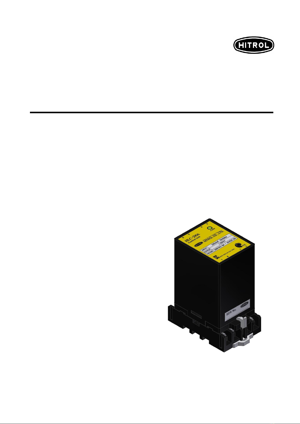
The image above is from HLC-200A.
Overview
Characteristics
Operating
Principle and
Composition
When the level switch connected to HLC-200 Series detects a liquid in the tank, a
leakage current flow and it is sensed by leakage current sensing circuit, and transistor is
activated. Accordingly, relay contact is changed and it can be used for alarm and/or
control signal.
■Easy to install (DIN Rail Type)
■Compact size
■Socket structure type for freely detachment
■Operating can be checked through LED lamp (High: Red, Low: Green)
■Sensitivity can be adjusted at the site if the sensor is too much sensitive to the conductivity
or foam of the liquid. (HLC-200A)
HLC-200 Series is a Level Control & Alarm Unit that controls and alarms by combining
with the level sensor (HE, HQ, HR Type) of the storage of tank. The signal of the level
sensor can control the upper and lower alarm of liquid and automatic supply of liquid
through HLC-200 Series, and the product can be installed inside the control panel.
HLC-200 Series Socket
DIN-Rail Mounting Button
Socket Locker
Serial No.
HLC-200 Series Body

HLC-200 Series
HITROL CO., LTD. 4
HLC-200 Series
HLC-200 Series
Actual product may have a tolerance slightly.
The image above is from HLC-200A.
Specifications
Dimensions
Model
HLC-200A
HLC-200F
Mounting
Panel Inside (DIN Rail or Bolting)
Ambient Temperature
-20℃~ +70℃
Power Source
AC 110V or 220V
@ 50/60Hz
DC +24V
@ DC +21V ~ DC+30V
Standby Power Consumption
AC 110V @ 0.5W /
AC 220V @ 0.8W
DC +24V @ 0.48W
Active Power Consumption
AC 110V @ 1.4W /
AC 220V @ 2W
DC +24V @ 1.1W
Output Voltage
AC 14V
DC +22V
Relay Contact
1-SPDT
Contact Load Capacity
AC 250V, 5A / DC 30V, 5A Max.
Weight
Body: 200g / Socket: 70g /
Total: 270g
Body: 120g / Socket: 70g /
Total: 190g
Housing
Body: ABS-Flame Resisting / Socket: PBT Glass
Approvals
KC
-
Unit: mm
<HLC-200 Series Socket>
<Assembly>
HLC-200 Series
HITROL CO., LTD. 5
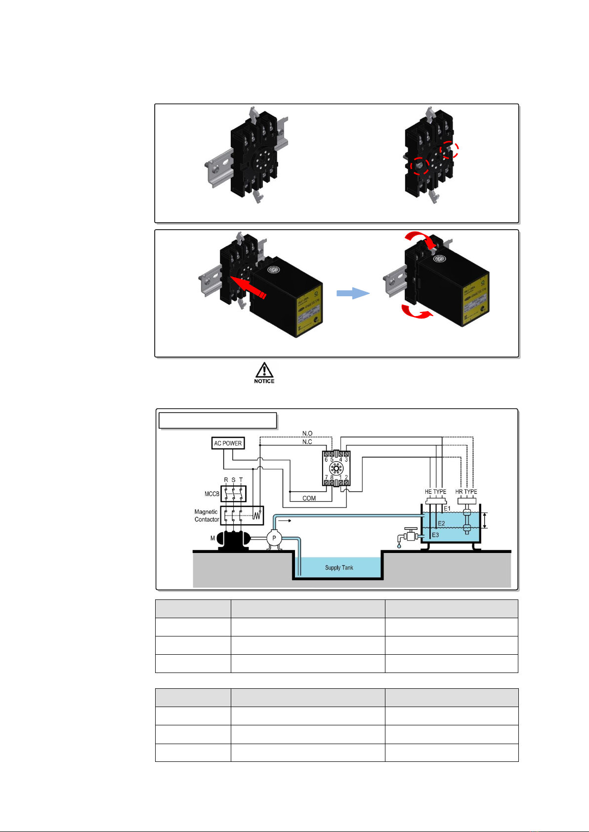
HLC-200 Series
■Installation
■HLC-200A Wiring
The image above is from HLC-200A.
Installation
and Wiring
Control
Drain
Pump
LED Color
Red
Green
Input
1, 3, 4
1, 3, 4
Output
8, 5
8, 6
Alarm
H. A
L. A
LED Color
Red
Green
Input
1, 4
1, 4
Output
8, 5
8, 6
(1) Install the socket DIN Rail (2) Fix it using bolts
- After assembling the HLC-200 Series body on the socket, lift the locker to fix the body.
Connection Diagram
HLC-200 Series
HITROL CO., LTD. 6
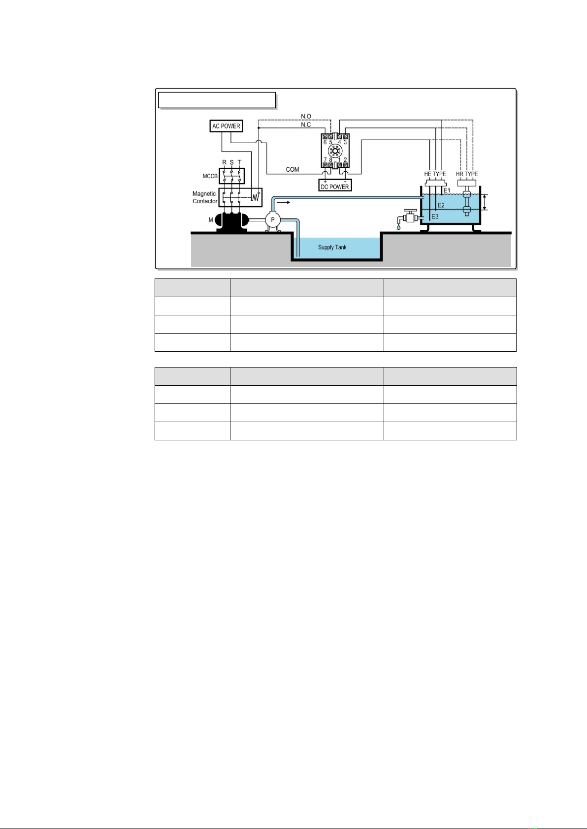
■HLC-200F Wiring
Control
Drain
Pump
LED Color
Red
Green
Input
1, 3, 4
1, 3, 4
Output
8, 5
8, 6
Alarm
H. A
L. A
LED Color
Red
Green
Input
1, 4
1, 4
Output
8, 5
8, 6
Connection Diagram
HLC-200 Series
HITROL CO., LTD. 7
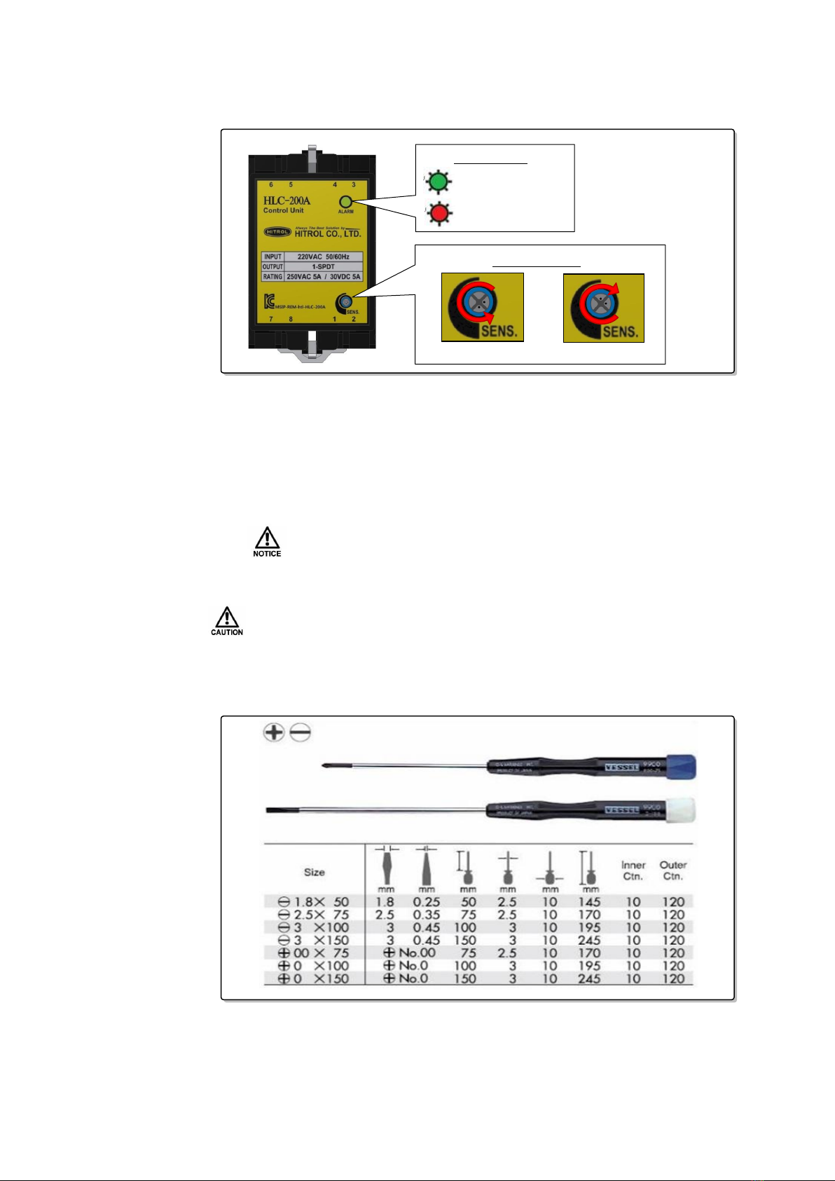
■Sensitivity Adjustment
Use only with electrode sensors.
Note that factory standard setting is for high sensitivity.
Sensitivity
Adjustment &
Recommended
Tool (HLC-200A)
■Recommended Tool
- When adjusting
SENS.
(Sensitivity), use the driver (-) 2.5x75 or less or (+) 00x75.
- Alarm Lamp: The red light is on when the liquid is detected, and the green light is on
when the liquid is not detected.
- Sensitivity Dial: It is a function to adjust the sensitivity in condition that it is too
sensitive to the conductivity of the medium or foam. Turning counter-clockwise is for
higher sensitivity and clockwise is for lower sensitivity.
Sensitivity Dial
High Sensitivity
Low Sensitivity
Default Status
Detector Status
Alarm Lamp
Maximum available adjustment range of potentiometer using for the sensitivity
dial is approximately 260°. (±130°based on 9 o’clock direction)
Pay attention to use it because it can be damaged if it is adjusted over the range.

HLC-200 Series
HITROL CO., LTD. 8
Precautions
for Removal
Precautions
for Installation
Safety and
Environment
Failure Check
and Solution
■Precautions for Use
- Do not disconnect the cable during use.
- Do not disconnect the product from the socket during use.
- Do not apply high impact to the product.
■Precautions for Wiring
- Make sure to wire contacts correctly. (Refer to Wiring)
- Wire and supply the power to the product after checking the specifications.
- Incorrect power voltage may cause damage to the product.
- Pay attention to prevent electric shock.
■Disposal of Product
- Make sure to separate the PCB and main unit from housing before disposing the products.
No part (ex. Mercury Switch) has influence on the environment, so no special attention is
required.
■Remove it with the power disconnected.
■Remove in reverse order of installation. (Power off Release the Locker Body
Disconnection Wiring Disconnection Socket Disconnection)
■It is recommended to use washers to prevent a loosening when the product is fixed
using bolts.
■Wiring shall be performed after checking of wiring diagram described in the manual or sticker.
■Make sure that the power source whether it is AC 110V, AC 220V, or DC +24V.
■It is recommended to use AWG 13 or 14 cable between the controller and level sensor, and
use shield cable in case that the distance between the controller and level sensor is quite long
(several hundred meters ~ 500m) and for low conductivity medium. (Non-recommendation
cables may result in some differences in operating and level sensing distances.)
■Check the LED color after applying of power. (High: Red, Low: Green)
■Power shall be applied after completing of installation.
■Relay contact does not work
- Check whether the LED lamp is on/off.
- Check the cable connection.
- Check the input voltage.
- Check the connection between the body and the socket.
- Check the level sensor wiring cable.
HLC-200 Series
HITROL CO., LTD. 9
DC voltage (HLC-200F) can cause sensor corrosion due to electrolysis.
Marking
Warranty
and Contact
■Warranty and Service
This product is subject to the warranty for 2 years of shipment and unpaid service
will be provided for any damage found under normal operating conditions. If it is
not about the failure of product, the service charge will be payable.
You can request A/S at our website or by contacting our headquarters.
■Headquarters ․Factory ․Laboratory Contact
ADDRESS:
HITROL CO., LTD 141, Palhakgol-gil, Jori-eup, Paju-si, Gyeonggi-do, Korea
T E L : 031-950-9700 (Headquarters & A/S)
F A X : 031-943-5600 (Headquarters & A/S)
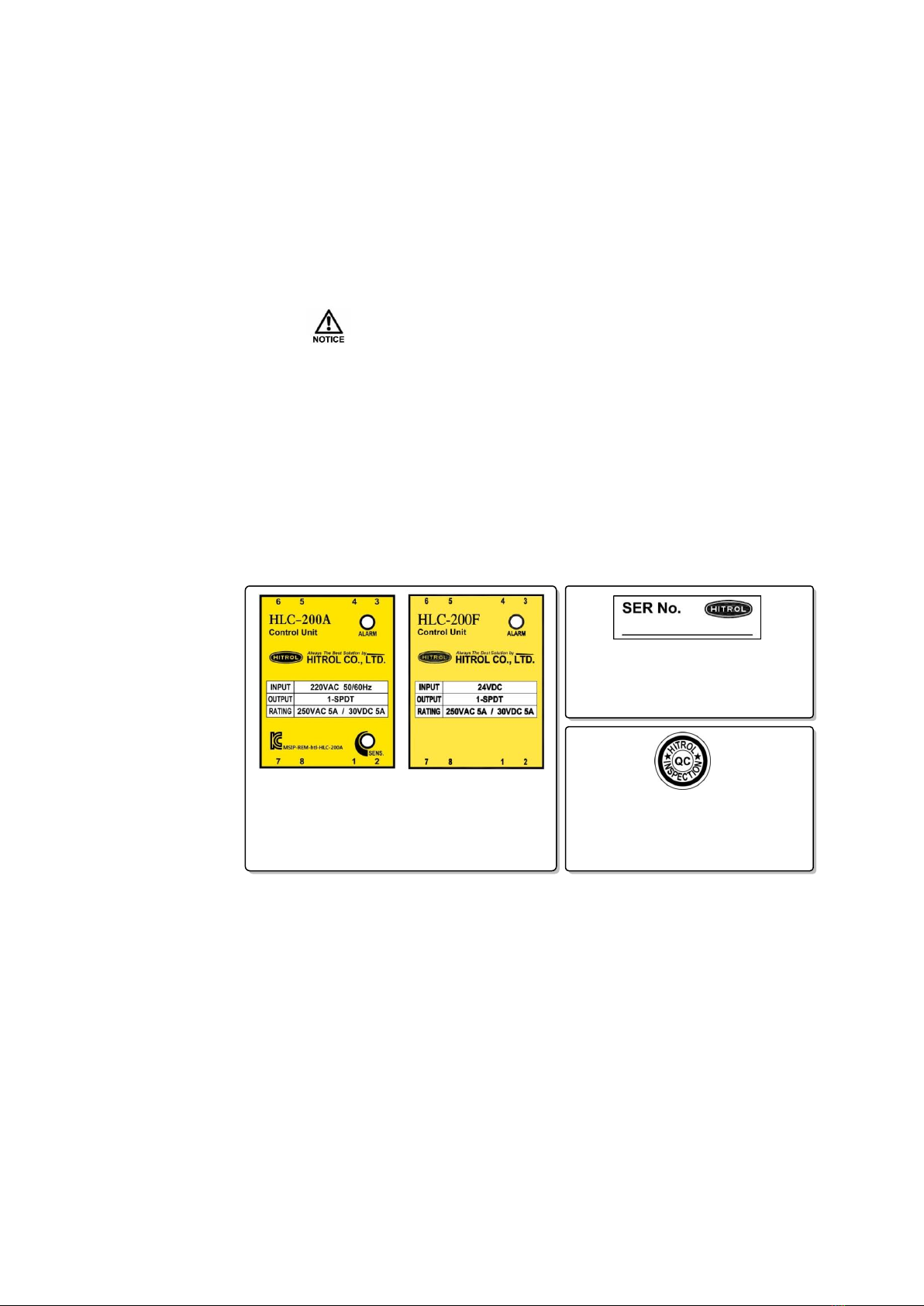
■Product Identification
- The product identification mark is attached onto housing and shows the model
name, serial number, and matters regarding input/output. The serial number is a
unique manufacturing number for the identification of products.
■Controller is normal, but not working
1) Electrode Type Level Switch
- If there is foreign matter or sediment such as lime on the bottom of tank, it may cause malfunction.
- Too low liquid conductivity can cause malfunction. (ex. Distilled Water)
- When wiring between controller and electrode is far apart, it may cause malfunction.
- Please refer to the cable recommendations between the controller and the sensor for
installation precautions (Page 9).
2) Float Type Level Switch
- Check that the float floats normally.
- Check the signal when the float operates normally.
- It is attached to the front of the product and the
model name and input/output information are
indicated.
- It is attached to the bottom of the product
and the serial number is indicated.
- It is attached to the top of the product and
means it has passed the internal quality
system.
This manual suits for next models
2
Table of contents
Other HITROL Laser Level manuals


