manuals.online logo
Brands
  1. Home
  2. •
  3. Brands
  4. •
  5. HITROL
  6. •
  7. Switch
  8. •
  9. HITROL HCC-95P Series User manual

HITROL HCC-95P Series User manual

HITROL CO., LTD.
User Manual
HCC-95P Series
Doc. no. : HCC95P_UM_Eng_Rev.0
1
1. Overview
HCC-95P(-Ex) Series is a capacitance type level switch and it detects a level of
medium by sensing of capacitance value change by dielectric constant of each
medium.
2. Operating Principle & Composition
When an air surrounding the electrode probe is replaced by other medium,
the capacitance value is changed according to the dielectric constant of the
medium. Once the electrode probe is touched by the medium, the capacitance
value is increased and the level switch activates relay output by converting of
the changed capacitance value to the electronic signal.
2
3. Specification
■ Weather-Proof Version
Model HCC-95P HCC-95PH HCC-95PW HCC-95PWH
Probe Type Rod(Flat) Rope
Mounting Screw or Flange
Ambient Temperature -20°C ~ +60°C
Process Temperature -40°C ~ +80℃ -40°C ~ +150℃ -40°C ~ +80℃ -40°C ~ +150℃
Process Pressure Vacuum~ 20kg/cm2(300#)
Power Source AC 90~240V, 50/60Hz (Std.), DC +24V (Opt.)
Output DPDT
Contact Rating AC 250V, 5A / DC 30V, 5A
Enclosure Weather-Proof (IP65)
Wetted Parts Material SUS 304, 316L with Teflon(Peek) SUS 304, 316L with Teflon
Process Connection PT 1”(M) Screw
Housing ; Cable Entry
PBT;PF1/2”(F),IP65
AL;PF1/2”(F),IP66
PBT;PF1/2”(F),IP65
AL;PF1/2”(F),IP66
AL;PF1/2”(F),IP66 AL;PF1/2”(F),IP66
■ Ex-Proof Version
Model HCC-95P-Ex HCC-95PH-Ex HCC-95PW-Ex HCC-95PWH-Ex
Probe Type Rod(Flat) Rope
Mounting Screw or Flange
Ambient Temperature -20°C ~ +60°C
Process Temperature -40°C ~ +80℃ -40°C ~ +150℃ -40°C ~ +80℃ -40°C ~ +150℃
Process Pressure Vacuum~ 20kg/cm2(300#)
Power Source AC 90~240V, 50/60Hz (Std.) / DC +24V (Opt.)
Output DPDT
Contact Rating AC 250V, 5A / DC 30V, 5A
Enclosure
Ex-proof Ex d IIC T5/T6(*), IP66 Ex d IIC T3/T4(*), IP66 Ex d IIC T5/T6(*), IP66 Ex d IIC T3/T4(*), IP66
Dust-proof Ex tD A21 IP66 T80℃ Ex tD A21 IP66 T150℃ Ex tD A21 IP66 T80℃ Ex tD A21 IP66 T150℃
Wetted Parts Material SUS 304, 316L with Teflon(Peek) SUS 304, 316L with Teflon
Process Connection PT 1”(M) Screw
Housing ; Cable Entry AL. ; PF 1/2”(F), IP66
(*) Explosion-proof Fluid Temp. & Grade: Max. 70℃ for T6
Max. 80℃ for T5
Max. 130℃ for T4
Max. 150℃ for T3
3
■ Amplifier Specification
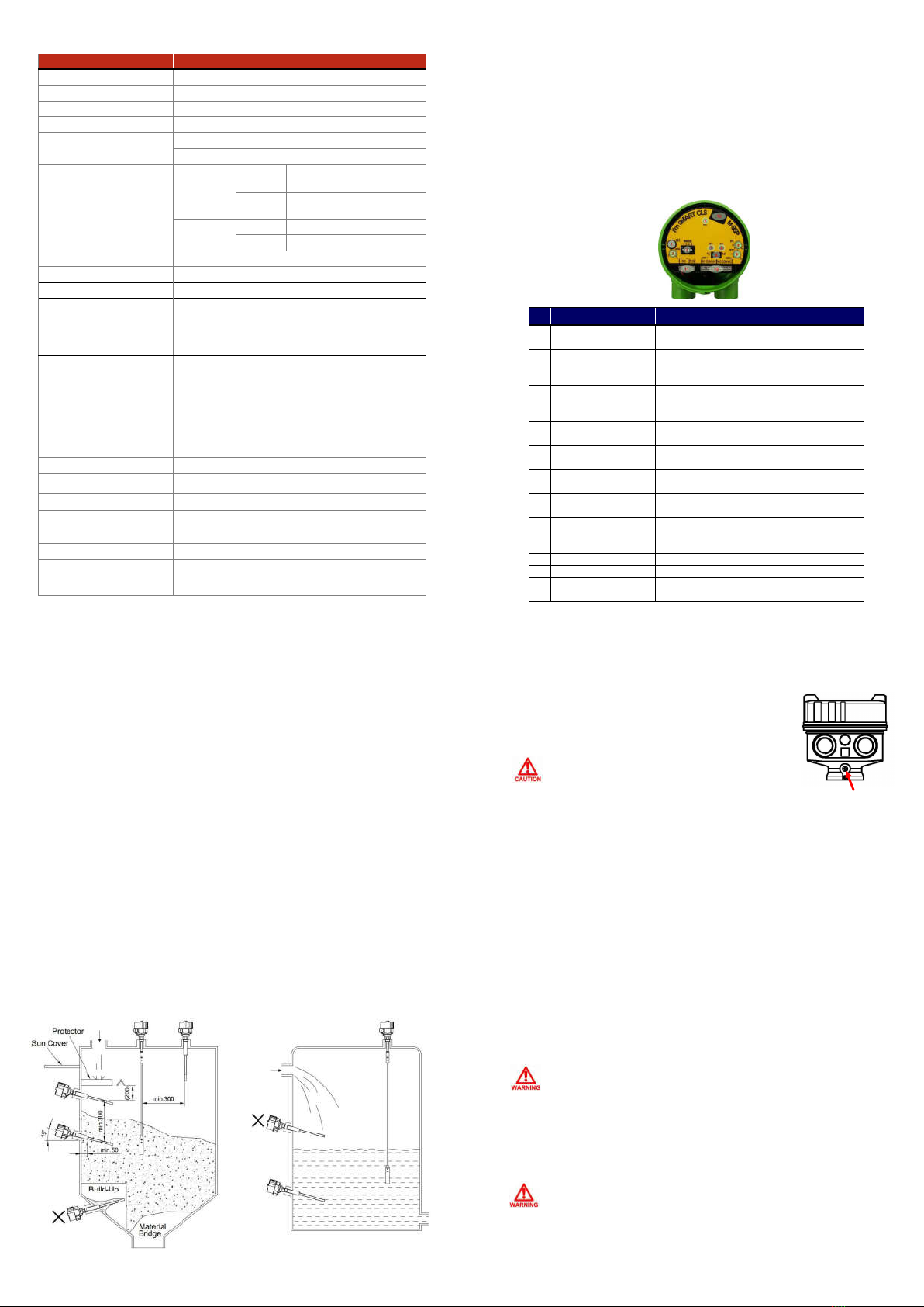
Module M-95P
Enclosure Weather Proof
Housing Material P.B.T / AL.C
Mounting Compact
Microprocessor 16 Bit Microprocessor
Supply Voltage AC Free (90V ~ 240V @ 50/60Hz)
DC+17V ~ +35V @ Typ.+24V
Power Consumption
AC Free
(90~240V)
Stand-by ■ AC 220V @ 7W
■ AC 110V @ 3.1W
Active ■ AC 220V @ 7.6W
■ AC 110V @ 3.9W
DV+24V Stand-by ■ DC + 24V @ 0.2W
Active ■ DC + 24V @ 0.96W
Oscillation Frequency 1MHz
Sensitivity Resolution 0.1pF
Dielectric Constant 2 @ Min. (Powder/Liquid)
Function (Adjustment)
■ Sensitivity
■ Relay Delay Time
■ Relay Return Time
■ Relay Contact Control (Normal/Reverse)
Sensitivity
■ RANGE: Measurement Sensitivity Adjustment Range
▶ Sensitivity Setting Range: 10pF ~ 150pF
▶ Sensitivity Setting Method: BCD DIP Switch
■ SEN. : Measurement Sensitivity Fine Adjustment
▶ Dry Contact Adjustment Range: Δ10pF
▶ Wet Contact Adjustment Range: Δ-5pF
Relay Delay Time Range 0.5Sec. @ Min / 1Sec. ~ 10Sec. @ 0.1Sec. Resolution
Relay Return Time Range 0.5Sec. @ Min / 1Sec. ~ 10Sec. @ 0.1Sec. Resolution
Relay Contact Out Control Normal Close @ Default
Relay Contact Rating DPDT : AC250V/5A, DC30V/5A
Status Indicator Bi-Color LED [Green / Red / Orange]
Detection Indicator Red LED
Relay Control Indicator Green LED
UART Monitoring
Ambient Temperature -20℃ ~ +80℃
4
Refer to Instruction Manual for Setting Guide.
4. Wiring and Amplifier Composition
■ Wiring
- Connect correctly AC (90~240V) or DC (+24V) power to the power specification.
- Make sure to connect the DC power with correct polarity (+, -).
- Do not connect the wire with the power connected.
- It provides DPDT output by default, wired COM and N.O terminals when
using the high alarm.
- External grounding shall be completed.
No Configuration Function
1 SET. ■ Autoset
○ Automatic Measurement and Standard of Capacitance on Tank
2 RANGE
■ Capacitive Measurement Sensitivity Range Setting
○ Sensitivity Setting Range: 10pF ~ 150pF
○ Sensitivity Setting Range: BCD Dip Switch
3 SEN.
■ Fine Tuning of Capacitance Measurement Sensitivity
○ Dry Contact Sensitivity Fine Adjustment Range: △10pF
○ Wet Contact Sensitivity Fine Adjustment Range: △-5pF
4 DT. ■ Relay Delay Time Adjustment
○ Time Range: 0.5s, 1s ~ 10s @ Adjustment 0.1s
5 RT. ■ Relay Return Time Adjustment
○ Time Range: 0.5s, 1s ~ 10s @ Adjustment 0.1s
6 Fail Safe Mode ■ Relay Transformation Adjustment
○ N.C ↔ N.O
7 DET. ■ Measurement Status LED
○ OFF → Red
8 RLY.
■ Relay Status LED
○ N.C: OFF → Green
○ N.O: Green → OFF
9 PWR ■ Power & Status Display
10 UART ■ M-95P Status Setting and Status Communication Port
11 Power ■ Power Connector (AC / DC)
12 Relay Out ■ Relay Contact Out (DPDT)
5
5. Precautions
■ Precautions for Installation
The capacitance type level switch can be installed in screw (PT, NPT, PF, etc.) and
flange (ANSI, JIS, DIN, etc.) as well as tri-clamp and other various locations.
Pay attention to the following matters during installation.
▶ Side Mounting Installation
Highly sensitive measurement is available because it measures the level by
whole of probe but it shall be installed slopingly, forwarding of sensor to
the bottom in order to avoid a malfunction caused by build-up of the
medium on the sensing probe.
▶ Top Mounting Installation
This installation is not much affected by build-up of the medium on the
probe but the sensitivity is lower than side mounting because it measures
the level by the end of probe only, and it is not suitable to detect a level of
the medium which has a lower dielectric constant.
6
■ Precautions for Grounding
▶ When connecting to an external ground, the ground
wire shall be 4 ㎟(4mmSQ).
■ Failure Check & Maintenance
▶ Inspection of Product
The life span of key parts depends on user’s environment and can be used optimally
through periodic check. Therefore, regular inspection ensures optimal performance of
product, so take regular inspection and maintenance at least every year. Inspection of the
appearance of the product shall be visually checked to see if there is any damage, and
the attachment of the medium or foreign substances to the sensor will make it worse, so
they shall be removed regularly. Be careful not to damage Teflon part during removal.
▶ Failure Check
1) Is power voltage connected correct?
2) Is power voltage supplied according to specifications correct?
3) Is cable wiring correct?
4) Is the Fail-Safe Mode setting correct?
5) Does the green LED turn on?
■ User Training
Make sure that the ambient temperature of housing is kept at -20℃ ~ +60℃. Ex-proof
products are designed according to Article 34 of the Industrial Safety and Health Act and
Article 58.4 of the Enforcement Rules of the same Act. (Refer to Instruction Manual for details.)
◈ More product information can be acquired at our website. (www.hitrol.com)
Make sure to insert a washer if the terminal lug is
removed from ground terminal and then re-connected.
(Loosening prevention)
Turn off the power of the product for maintenance.
In an explosion area, do not disassemble when power is supplied.
Do not apply a non-ex-proof product in an Ex-proof zone. Ex-proof
products can only be installed at zone 1 and 2 of environment. It shall
be installed in compliance with the ex-proof temperature rating and
the applied fluid temperature.
External Grounding

Other manuals for HCC-95P Series

3

This manual suits for next models

4

Other HITROL Switch manuals

HITROL HCC-95P Series User manual

HITROL

HITROL HCC-95P Series User manual

HITROL HTM-930 User manual

HITROL

HITROL HTM-930 User manual

HITROL HCC-96RF-R Series User manual

HITROL

HITROL HCC-96RF-R Series User manual

HITROL HQ Series User manual

HITROL

HITROL HQ Series User manual

HITROL HTM-20N Series User manual

HITROL

HITROL HTM-20N Series User manual

HITROL HNV-970 Series User manual

HITROL

HITROL HNV-970 Series User manual

HITROL HTM-20N Series User manual

HITROL

HITROL HTM-20N Series User manual

HITROL HCC-95P Series User manual

HITROL

HITROL HCC-95P Series User manual

HITROL HTM (HPV)-20N Series User manual

HITROL

HITROL HTM (HPV)-20N Series User manual

HITROL HLC-901 Series User manual

HITROL

HITROL HLC-901 Series User manual

HITROL HTM-20N Series User manual

HITROL

HITROL HTM-20N Series User manual

HITROL HCC-95P Series User manual

HITROL

HITROL HCC-95P Series User manual

HITROL HLV Series User manual

HITROL

HITROL HLV Series User manual

HITROL HR-10 Series User manual

HITROL

HITROL HR-10 Series User manual

HITROL HM-90S Series User manual

HITROL

HITROL HM-90S Series User manual

HITROL HTM-30N Series User manual

HITROL

HITROL HTM-30N Series User manual

HITROL HLC-901N Series User manual

HITROL

HITROL HLC-901N Series User manual

HITROL HTM-30N-Ex User manual

HITROL

HITROL HTM-30N-Ex User manual

HITROL HTML-S User manual

HITROL

HITROL HTML-S User manual

HITROL HM-90-Ex Series User manual

HITROL

HITROL HM-90-Ex Series User manual

HITROL HM-95 Series User manual

HITROL

HITROL HM-95 Series User manual

HITROL HR-30 User manual

HITROL

HITROL HR-30 User manual

HITROL HM-95 Series User manual

HITROL

HITROL HM-95 Series User manual

Popular Switch manuals by other brands

Exelon connected ANNAPOLIS BGE G550 quick start guide

Exelon

Exelon connected ANNAPOLIS BGE G550 quick start guide

Buffalo BS-GS20 Series user manual

Buffalo

Buffalo BS-GS20 Series user manual

Kramer VP-730 user manual

Kramer

Kramer VP-730 user manual

Simple Control HUB user guide

Simple Control

Simple Control HUB user guide

Asco 7000 Series Operator's manual

Asco

Asco 7000 Series Operator's manual

Cisco SPS208G datasheet

Cisco

Cisco SPS208G datasheet

LEGRAND 0 672 33 quick start guide

LEGRAND

LEGRAND 0 672 33 quick start guide

Aluratek AVW02H quick start guide

Aluratek

Aluratek AVW02H quick start guide

Moxa Technologies EtherDevice EDS-728 Series Hardware installation guide

Moxa Technologies

Moxa Technologies EtherDevice EDS-728 Series Hardware installation guide

ZooZ ZEN73 user manual

ZooZ

ZooZ ZEN73 user manual

SimworX Pro Series ARB Lever and Brake Bias Set Setup manual

SimworX

SimworX Pro Series ARB Lever and Brake Bias Set Setup manual

LEGRAND Raritan Dominion KX III Quick setup guide

LEGRAND

LEGRAND Raritan Dominion KX III Quick setup guide

SMC Networks TigerStack II SMC8848M Management guide

SMC Networks

SMC Networks TigerStack II SMC8848M Management guide

schmersal ZF 232 Series operating instructions

schmersal

schmersal ZF 232 Series operating instructions

New Star NS832DM user manual

New Star

New Star NS832DM user manual

Optex SW-1 installation manual

Optex

Optex SW-1 installation manual

SIIG 1394 Quick installation guide

SIIG

SIIG 1394 Quick installation guide

DeLOCK 64236 user manual

DeLOCK

DeLOCK 64236 user manual

manuals.online logo
manuals.online logoBrands
  • About & Mission
  • Contact us
  • Privacy Policy
  • Terms and Conditions

Copyright 2025 Manuals.Online. All Rights Reserved.