Hjelpemiddelspesialisten DELTA BUGGY User manual

Hjelpemiddelspesialisten AS, Rosenholmveien 22, 1252 Oslo
Telefon: +47 66 81 60 70 - Telefaks: +47 66 81 60 71
E-post: [email protected] - Internett: www.hm-spes.no


DELTA BUGGY
INSTRUCTION
MANUAL
PLEASE READ THIS BEFORE USING YOUR DELTA
BUGGY AND KEEP IN A SAFE PLACE FOR FUTURE
REFERENCE

♦ ALWAYS DEPLOY THE ANTI-TIPPER AND THE BRAKES
WHEN PARKED AND BEFORE TRANSFERRING IN OR OUT OF
THE BUGGY. The Delta buggy is designed to be easy to tip
backwards for improved manoeuvrability and easier handling. NB.
THE ANTI-TIPPER WILL NOT BE AS EFFECTIVE ON SOFT
GROUND LIKE SAND.
♦ DO NOT HANG ANY LUGGAGE ON THE HANDLE OR
BACKREST FRAME. This can cause the buggy to tip backwards.
♦ WHEN ASSEMBLING THE BUGGY CHECK THAT QUICK
RELEASE WHEELS ARE SECURELY ATTACHED.
♦ READ THE INSTRUCTIONS BEFORE USE; PAY
PARTICULAR ATTENTION TO ITEMS WITH THE WARNING
TRIANGLE.
♦ ALWAYS HOLD ON TO THE BUGGY IN USE. TAKE
EXTRA CARE ON INCLINES. A wrist strap is provided for extra
security.
♦ ALWAYS USE THE LAP BELT TO KEEP THE CHILD SAFE.
The shoulder and groin straps of the harness can be removed if not
required.
♦ WHEN OPERATING THE PARK BRAKES CHECK THAT
THEY ARE WORKING EFFECTIVELY AND DEPLOY THE ANTI-
TIPPER BEFORE RELEASING THE BUGGY.
♦ Do not allow the child to climb into the buggy unassisted.
♦ Attempting to negotiate steps and stairs is dangerous, be sure
that you and your helper can support the weight of the buggy and
occupant. Do not attempt more than a short run of steps without at
least two carers.
♦ The handle mounting is flexible to reduce hand/wrist fatigue.
Do not lift the buggy by the handle when occupied; use the frame or
section of tube between the handle adjusters and frame.
IMPORTANT SAFETY NOTES

Pg.22

IMPORTANT SAFETY NOTES
♦FOLLOW THE PRE-USE SAFETY CHECKS BEFORE USE, REFER TO
THE CARE AND MAINTENANCE INSTRUCTIONS.
♦If any part is damaged or fails to operate correctly do not continue to
use the buggy. Read the care and maintenance instructions and contact
Delichon for advice if necessary.
♦Take care when the rear wheels are removed to avoid damage to the
brake mechanisms; use the protective discs provided.
♦Never leave a child unattended in the buggy.
♦Do not overload the buggy with additional children or luggage. See
dimension and limits table on page 6.
♦Do not allow children to play with or climb on the buggy.
♦No adaptations or modifications must be made to the buggy without
approval from the manufacturer.
♦Do not place heavy objects on top of the frame when it is being stored or
transported.
♦Keep your buggy clean and in good condition for optimum performance
–see maintenance instructions.
♦THE DELTA BUGGY IS NOT SUITABLE FOR TRANSPORTING THE
OCCUPANT IN A MOTOR VEHICLE.
Pg.3

Description
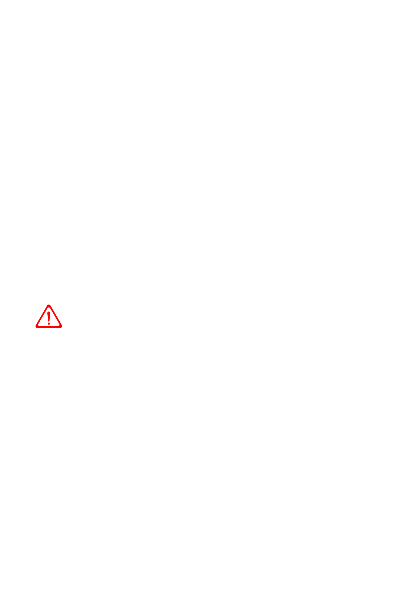
The Delta Buggy is designed to enable access to areas where most wheelchairs would
be unsuitable; countryside paths for example.
The fabric seat of the Delta is designed to provide comfort and support to the user; it
is not however intended as a primary seating system but for occasional use.
When in the buggy the occupant should be supervised at all times by a carer.
All attendants/carers should be familiar with the user instructions before use.
A lap belt and shoulder straps are provided, the lap belt should be used at all times for
safety. Foot straps and groin pad may also be provided.
The rear wheels have drum brakes operated by hand levers on the push handle, these
act to slow down the buggy or stop it from rolling back on a hill. The brake levers are
fitted with a lock that allows brakes to be used for parking by keeping them on when
the carer lets go of the handle.
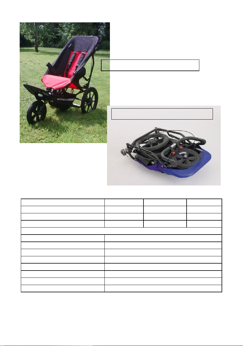
The design allows easy and compact folding and (optionally) quick release removal of
the wheels for transit; discs are provided to protect the brakes when the wheels are
removed. The large frame is available with two sizes of fabric seat which are
interchangeable.
The centre of gravity of the buggy and occupant is close to the rear axle to make
tipping back for steering and negotiating obstacles easier. The axle position can be
adjusted to fine tune the balance for the individual user. A foot-operated stabiliser,
which must be deployed when parked, is mounted on the rear of the frame to
prevent tipping.
A luggage carrier under the seat may be provided. Do not hang luggage on the handle.
Accessories
A transport bag is available as an extra, to help to protect the buggy during storage or
transit. A wedge shaped seat cushion is available to reduce hip flexion and raise the
occupant in the seat. Rain covers are available for the small and medium Delta Buggy
only and must be used in conjunction with a sun-hood. Sun-hoods are available for all
sizes. Double width rear wheels are available to make pushing the buggy easier on soft
ground.
Pg.4

Bungee cord
Lap belt strap
Shoulder
strap
Side of seat
hammock
FIG. 24
The lap belt and shoulder straps are threaded through a three bar buckle on the back
corner of the seat (see fig. 24).
Remove the adjustable (pronged)
part of the buckles from the straps
and the bungee cords from the
hammock before washing.
Pg.21
Shoulder Strap
Attach with
Velcro®
Slide Pad Up
Over Buckle
FIG. 23 Fitting the Shoulder
Straps and Pads
FIG. 25
Medium bungee
attachment
Large bungee
attachment
point
Regular Checks
The Delta buggy should be inspected by a competent person every 6 months for
adjustment and wear. The following items should be checked:
♦Park brake adjustment, brake cable and brake pad wear or damage.
♦Anti-tipper function and secure locking into place; when deployed the end of
anti-tipper should be approx. 22mm from the ground.
♦Security of the quick release wheel attachments.
♦Wear to folding joints. If there is excessive movement in the joints, take out a
stainless steel screw to inspect the polymer bearing that protects the aluminium
joint from the fixing screw. The bearings can be replaced if necessary.
♦Wear to the handle adjusters clutch mechanism. When the handle does not lock
securely the adjusters should be replaced.
♦That all screws and fixings are secure; folding joint fixings should not be over
tightened.
♦Condition and secure attachment of the foam that covers the handle to backrest
frame joint.
♦Tyre wear and inflation pressure.
♦Secure attachment of footrest; adjust height if required.
♦Check condition of harness and foot-straps; replace if necessary.
Spares are available from Delichon and are supplied with fitting instructions.
If any part is damaged, loose or not working correctly do not
continue to use the buggy until rectified.
To remove seat hammock for washing or replacement;
Look carefully at how the seat is attached to the frame before and during removal to
make replacing it easier, in particular take note of how the straps and the bungee
cords are threaded.
The top of the fabric seat fits over the frame, most of the occupants weight is
supported through this section. The sides and front of the fabric seat are attached to
the frame by poppers, the number of these varies with the size of the frame.
Between the front corners of the seat there is a 40mm wide webbing strap which
must pass around the frame and fasten tightly underneath.
The rear corners are held in place with bungee cords which pass through the webbing
loops on the seat and hook onto slots in the frame brackets. The slots are in the axle
adjuster plate on the medium Delta and on the rear frame bracket of the large Delta
(see fig. 25)
Pg.20
Dimensions and Limits
NOTE: the fabric seat dimensions change when someone sits in it; a larger
range of occupants can be comfortably accommodated than is suggested
by the seat width and depth measurements.
SMALL DELTA
Approx. dimensions in mm
Length
Width
Height
Overall dimensions
1080 - 1280
570
930 - 1040
Overall folded dimensions
850
540
300
Maximum occupant weight
40kg
Maximum occupant height
1.3m
Maximum luggage weight
6kg
Seat to footrest height
240 - 360
Push handle height
665 - 1030
Rear wheel diameter
305
Front wheel diameter
305
Buggy weight
13kg
FIG. 2 –FOLDED DELTA BUGGY
FIG. 1 –MEDIUM DELTA BUGGY
Pg.5

MEDIUM DELTA
Approx. dimensions in mm
Length
Width
Height
Overall dimensions
1220-1270
625
1020-1050
Overall folded dimensions
880
560
240
Maximum occupant weight
55kg
Maximum occupant height
1.5m
Maximum luggage weight
10kg
Seat to footrest height
275- 420
Push handle height
880-1050
Rear wheel diameter
395
Front wheel diameter
305
Buggy weight
13.5kg
INTERMEDIATE DELTA
Approx. dimensions in mm
Length
Width
Height
Overall dimensions
1390-1430
695
1170
Overall folded dimensions
1100
620
250
Maximum occupant weight
60kg
Maximum occupant height
1.65m
Maximum luggage weight
10kg
Seat to footrest height
380 - 550
Push handle height
900-1070
Rear wheel diameter
395
Front wheel diameter
305
Buggy weight
14kg
LARGE DELTA
Approx. dimensions in mm
Length
Width
Height
Overall dimensions
1390-1430
695
1170
Overall folded dimensions
1100
620
250
Maximum occupant weight
70kg
Maximum occupant height
1.8m
Maximum luggage weight
10kg
Seat to footrest height
340 - 510
Push handle height
900 - 1070
Rear wheel diameter
395
Front wheel diameter
305
Buggy weight
14kg
Pg.6

Care & Maintenance Instructions
Cleaning
The fabric seat, the harness pads, the luggage carrier, the transport bag, the sun-hood
and storm-cover are constructed mainly of waterproofed fabrics that can be sponged
with warm soapy water, brushed with a soft brush and/or hosed down. Rinse off any
soap with clean water. DO NOT IRON.
The removable webbing straps can be machine-washed at 30°C to 40°C –remove the
parts of the buckles that are not stitched on first.
The frame, wheels and footrest can be cleaned by sponging with warm soapy water,
brushing with a soft brush and/or hosing down. Rise with clean water and remove the
rear wheels to allow the brakes to dry.
If the buggy should be exposed to salt water wash off as soon as possible with fresh
water to reduce corrosion.
Protecting the metal parts of the brake mechanism with a water repellent agent such
as Duck Oil® is advised to prolong their life and aid cleaning but avoid getting this on
the brake pads or drums.
Tyres
Standard tyres should be inflated to between 20 and 30p.s.i. (1.4 and 2 bar). Beach
wheel tyres should be inflated to between 10 and 15 p.s.i. (0.7 and 1 bar approx). A
car foot pump or bicycle pump with the correct adaptor (similar size to mountain
bike) can be used. A puncture protection material such as ‘Green Slime®’, available
from most cycle shops, can be used. Spare tyres and inner tubes can be purchased
from cycle shops or Delichon Limited.
Adjusting the Brakes
As the brake pads wear, adjustment will be necessary. To adjust the brakes release
the lock nut on the park brake adjuster (see fig. 22) and screw the adjuster out
slightly, re-check the brakes and adjust further if needed. When satisfactory park
brake function has been attained tighten the lock nut taking care not to move the
adjuster.
Pg.19
Park Brake
Adjuster
FIG. 22
Warranty
Your Delta Buggy is guaranteed for one year from delivery.
The warranty does not cover tyres, inner tubes, brake pads/shoes or damage caused
by misuse or neglect.
Spare parts and advice are available from Delichon Limited. Moving parts subject to
wear and most likely to need replacement are tyres, brake components, polymer
bearings in the frame joints, webbing straps and the handle adjuster mechanisms.
Pre-use Safety Checks
BEFORE EACH USE CHECK THE FOLLOWING ITEMS
♦That the wheels are securely attached (see pages 7 & 8)
♦That the anti-tipper is operating correctly, and is deployed before transferring
anyone into the seat.
♦That the park brakes are working; try by pushing the buggy with the brakes on.
♦That no parts appear broken or loose.
♦That the tyres are inflated to the correct pressures. Low tyre pressure will cause
instability and make pushing the buggy more difficult.
Pg.18
Instructions for Use
See Pre-Use Safety Checks Before Use.
To unfold the Delta Buggy; place the folded frame on the ground with the handle
uppermost, unclip the retaining strap. Put the wheels to one side.
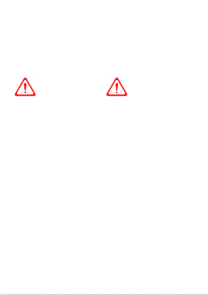
Unfold the handle first, by pushing in the buttons on the inside of the handle hinge
and rotating the handle upwards.
Lift the top of the backrest and push down the sliders on the side of the frame as far
as they will go (see fig. 8). Clip the ends of the retaining strap together under the seat.
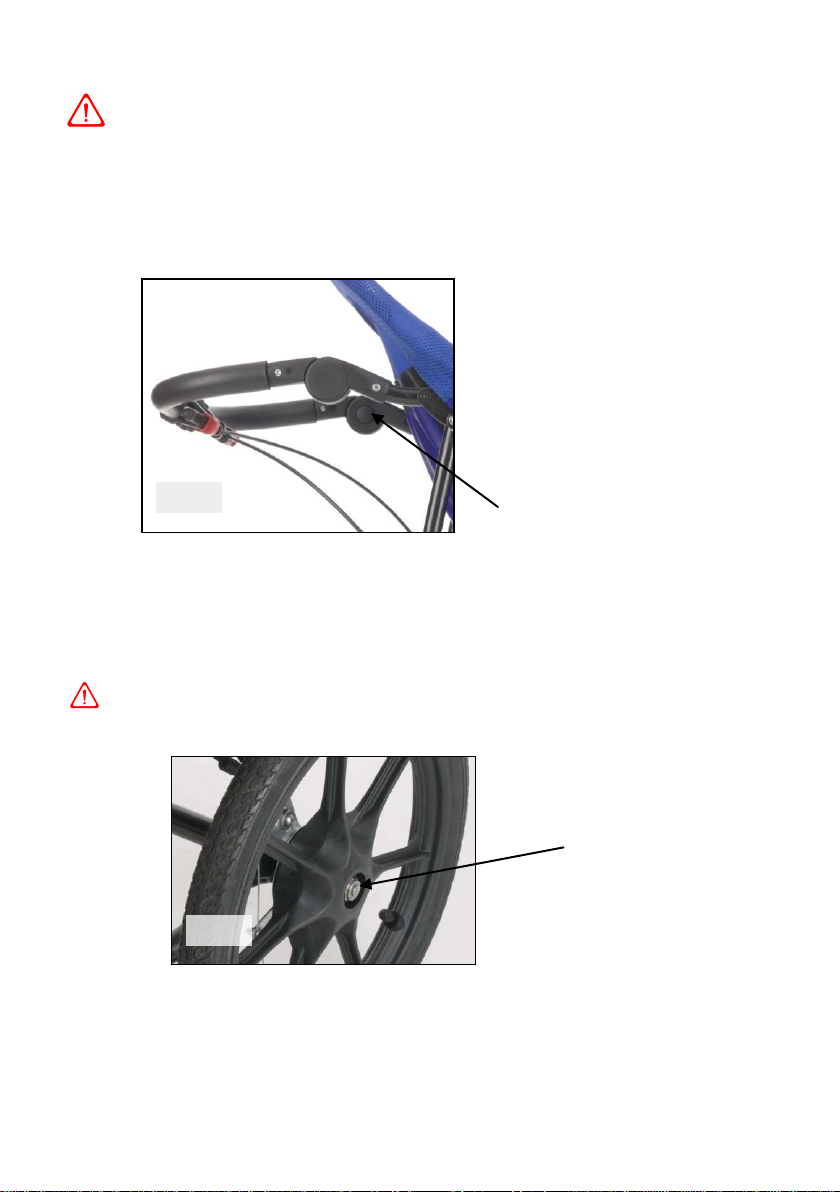
To fit the rear wheels; first check that the park brakes are not on. Take one wheel,
push and hold down the button on the centre of the hub and insert the axle as far as
it will go into the hole in the middle of the rear brake. Release the button.
PULL THE WHEEL TO CHECK THAT IS SECURELY ATTACHED. Repeat with
the other wheel.
Handle Adjuster
Button
FIG. 3
Wheel Release
Button
FIG. 4
Pg.7

Locating
Pins
FIG. 6
To fit the front wheel; first check that the quick release lever on the front wheel
axle is released (see fig. 5). Locate the ends of the axle into the front forks and lock
the quick release lever.
PULL THE WHEEL TO CHECK THAT IT IS SECURE.
DEPLOY THE ANTI- TIPPER AND ENGAGE THE PARK BRAKES
BEFORE PUTTING SOMEONE INTO THE BUGGY.
To deploy the anti-tipper; push down gently with your foot on the stainless steel
tube and flip it into the centre where it clicks into place; push down near to the bend
in the tube not on the end.
To fold down the footrest; pull the two rings on the underside of the footplate to
retract the spring loaded locating pins and fold down –the pins should release easily
do not force them. Let go of the rings to lock the footrest in place.
The height of the footrest may need to be adjusted
before use - see instructions below.
The footrest can be removed to make more
space during transfer in or out of the buggy.
To remove the footrest pull on the locating
pins and fold the footrest up as far as it will go;
keeping hold of the rings lift the footrest
upwards parallel to the frame tube.
The foot-straps are designed to be long
enough to remain under the loops on the
footrest while positioning the foot.
Pg.8
Quick Release
Lever in Locked
Position
FIG. 5

Screw C
Screw D
Screw E
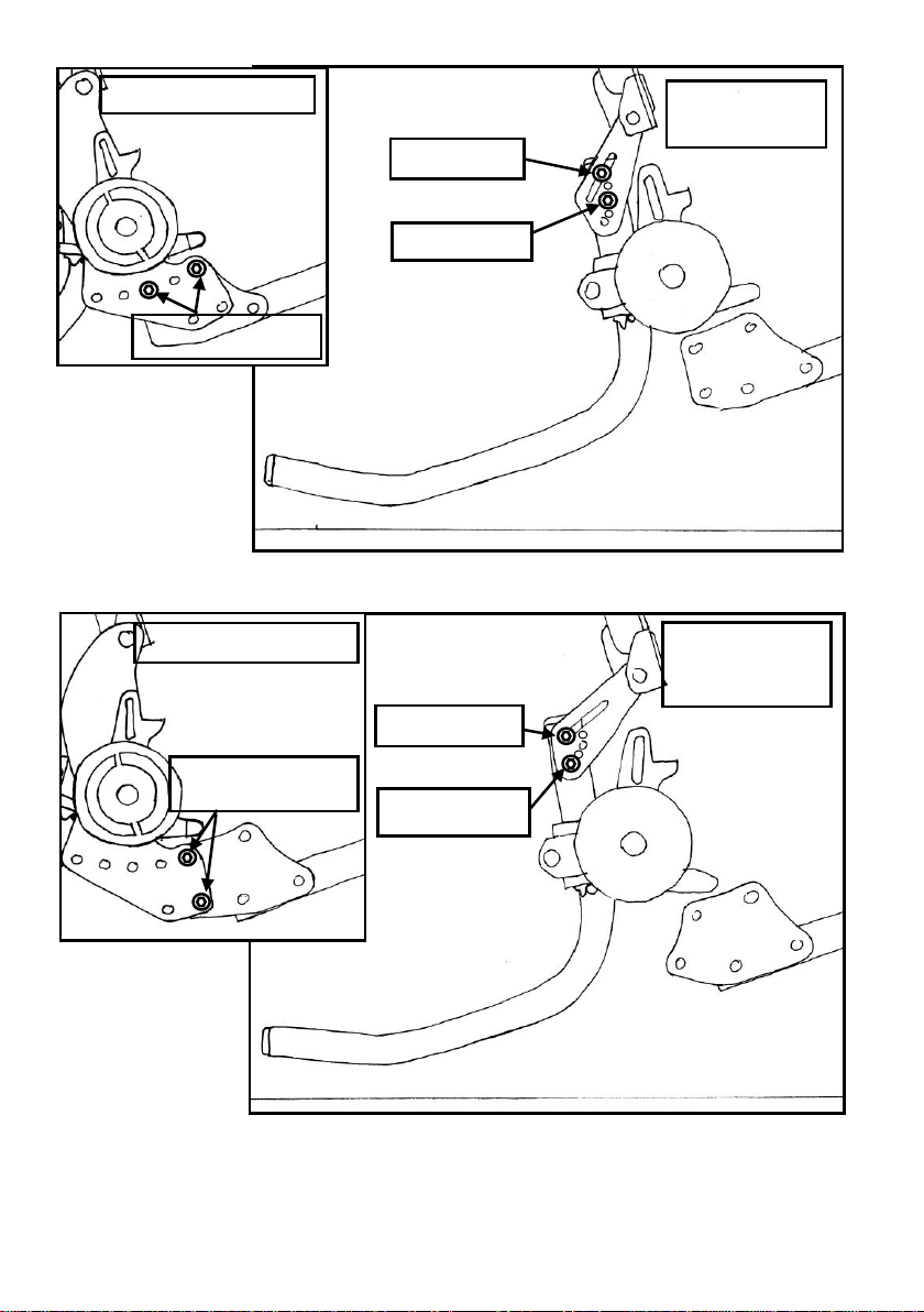
To adjust the anti-tipper position; first; loosen screws C & E. Then remove
screw D; be careful not to lose the washers. Rotate the anti-tipper assembly around
the axle to position 1 - 5 to suit the axle setting. Line up the appropriate hole or slot
in the adjuster plates and replace screw D; there should be spring washers between
the plates and the tube and plain washers under the screw head and the nut (see
diagram below). The end of the anti-tipper tube should be approximately 22mm from
the floor when deployed on a level surface.
Pg.17
Spacing
Plates
Flat
Washers
FIG.21
FIG. 20
Pg. 16
AXLE POSITION 3
SCREWS A & B
ANTI-TIPPER
SETTING 3
SCREW D
SCREW E
AXLE POSITION 5
SCREWS A & B
ANTI-TIPPER
SETTING 5
SCREW D
SCREW E
FIG. 18
FIG. 19

FIG 8.
Lap Pad
Park-Brake Latch
FIG. 7
To engage the park brakes;
pull the brake levers and engage
the red latch into the last notch on
the brake lever housing.
TO TEST THAT THE PARK-
BRAKES ARE WORKING TRY
PUSHING THE BUGGY; THE
REAR WHEELS SHOULD BE
LOCKED
Adjusting the Harness
The harness is attached to two buckles at the back corners of the seat; the length of
the two sides of the lap belt can be adjusted via these buckles. The lap belt is
tightened by using the centre buckle on the lap pad. The lap belt should be used at all
times to keep your child safely in the buggy.
The shoulder straps automatically adjust to the correct height when tightened by
sliding up or down the backrest.
The shoulder straps can be removed if not required by pulling the pad over the buckle
and undoing the Velcro® fastening. The bottom part of the shoulder strap can be
tucked out of the way under the seat.
The straps can be secured out of the way when transferring someone into and out of
the seat by using the Velcro® on the ends of the straps and under the lap pad buckle
to attach them to the side pads and the Velcro® patch on the right hand side of the
cover (see fig. 12).
The groin strap is
positioned by passing one
end of the lap belt through
the webbing loop on the
front of the pad before
fastening the lap belt. The
groin strap is attached to
the seat canvas the strap
passing through the
required loop on the canvas
and securing with the buckle
(see Fig 13).
Pg.9
Footrest Clamp
FIG. 9
Footrest Hook
Footrest
Adjusting
Screws
To adjust the footrest height;
first remove the footrest (see
page 8). Loosen the footrest
adjusting screws (see fig. 9) and
slide the footrest clamps up or
down the frame tubes to the
desired height.
Adjust the position of the clamps
so that they are at equal heights
and the footrest hooks are in line
with the frame.
Tighten the screws and check that
the footrest fits securely. There
should be about 1mm clearance
between the brackets on the
footrest and the footrest hooks.
The foot-straps are designed to be
long enough to remain under the
loops on the footrest while
positioning the foot.
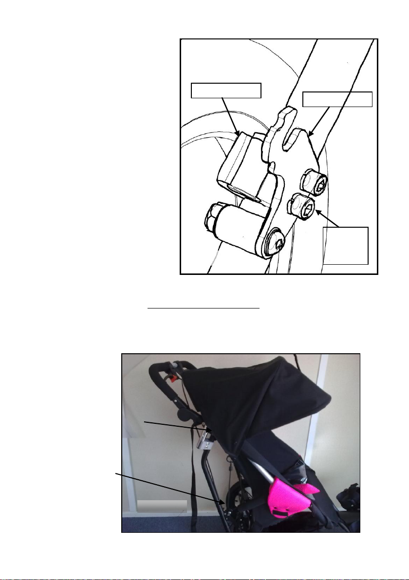
To attach the sun-hood; with the sun-hood folded, fit the back of the hood
over the top of the backrest. Carefully insert the ends of the wire frame into the
holes in the handle bracket and push them in as far as they go. Hook the ends of the
bungee cords onto the slot in the rear frame bracket.
Pg.10
Attach bungee to slot in
frame bracket.
Frame of hood fits into
holes in handle bracket.
FIG. 10
Fitting the Beach Wheels
The beach wheels are attached to the buggy with quick release axles similar to the
standard wheels (but longer). The release button is deeper below the outside of the
hub.
Make sure that the axles are fully pushed down into the hub - they may be quite tight.
ENSURE THAT THE WHEELS ARE SECURE BEFORE USE.
ADJUSTING THE REAR AXLE POSITION OF THE DELTA BUGGY
The new Delta buggy has an adjustable axle position to change the balance of the
buggy making it less or more ‘tippy’. The Delta buggy is designed to be balanced so
that it is easy to manoeuvre. The default axle setting is in the most forward position.
For some occupants whose centre of gravity is further back in the buggy due to body
shape the axle can be moved further back.
To adjust the axle position; lay the buggy on its side and remove the screws A & B
from both sides of the frame.
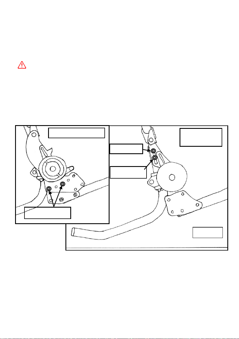
There are five possible positions; positions 1, 3 & 5 are shown in the diagrams. Rotate
the axle assembly to line up the holes in the desired position. Replace the screws with
their washers, one side at a time. The anti-tipper must be adjusted to the
correct position corresponding to the axle (see pg.16).
Pg.15
ANTI-TIPPER
SETTING 1
SCREW D
SCREW E
AXLE POSITION 1
SCREWS A & B
FIG. 17
Table of contents


