HK Instruments PS Series User manual

Thank you for choosing an HK Instruments PS Series Differential
Pressure Switch. The PS Series is intended for use in commercial
environments. It is designed with eld selectable setpoint adjustment to
meet your job requirements.
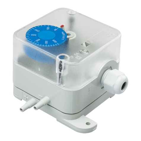
The PS Series Differential Pressure Switches is comprised of the PS2.5
with range from 0.15 − 2.50 inWC and the DPT5.0 with range from 0.5 −
5.0 inWC. All PS Series Differential Pressure Switches are available with
NIST standard calibration certicates.
APPLICATIONS
PS series devices are commonly used in HVAC/R systems for:
• fan, blower and filter monitoring
• pressure and flow monitoring
• valve and damper monitoring
Copyright HK Instruments Installation Version 1.0 2012
DIFFERENTIAL PRESSURE SWITCHES - AIR
PS Series
INTRODUCTION WARNING
INSTALLATION
INSTRUCTIONS
●READ THESE INSTRUCTIONS CAREFULLY BEFORE ATTEMPTING
TO INSTALL, OPERATE OR SERVICE THIS DEVICE.
●Failure to observe safety information and comply with instructions could
result in PERSONAL INJURY, DEATH AND/OR PROPERTY DAMAGE.
●To avoid electrical shock or damage to equipment, disconnect power
before installing or servicing and use only wiring with insulation rated for
full device operating voltage.
●To avoid potential re and/or explosion do not use in potentially
flammable or explosive atmospheres.
●Retain these instructions for future reference.
●This product, when installed, will be part of an engineered system whose
specications and performance characteristics are not designed or
controlled by HK Instruments, Inc. Review applications and national an
local codes to assure that the installation will be functional and safe. Use
only experienced, knowledgeable, technicians to install this device.
SPECIFICATIONS
Performance
Accuracy (at applied pressure)
At Low Limit (Typical):
PS2.5 = ± 0.02 inWC
PS5.0 = ± 0.04 inWC
Overpressure:
Proof Pressure: 100 inWC
Burst Pressure: 200 inWC (50kPa)
Technical Specications
Media Compatibility:
Dry air or non-aggressive gases
Measuring units:
inWC
Measuremewnt Range:
PS2.5 = 0.15 − 2.5 inWC
PS5.0 = 0.50 − 5.0 inWC
Environment:
Operating Temperature: -4 − 140°F (-20 − 60°C)
Storage Temperature: -40 − 158°F (-20 − 85°C)
Humidity: 0 to 95% RH, non condensing
Physical
Case:
Dimensions: 4.125” x 2.875” x 2.5“
(105 x 73 x 63)mm
Weight: 5.3 oz (150 gm)
Mounting: 2 each 3/16” (4.3mm) screw holes,
one slotted
Materials: Case: ABS (UL 94 V-0 Approved)
Cover: PC (UL 94 V-0 Approved)
Membrane: Silicone
Protection standard: IP54 / NEMA3
Electrical Connections:
3 screw terminals
Wire: 12-24AWG (0.2 – 1.5 mm
2
)
Cable Entry:
Strain Relief: M16
Knockout : 0.625” (16mm)
Pressure Fittings:
Pressure Fittings integral to case
Material: ABS (UL 94 V-0 Approved)
Size: 3/16” (5.0mm)
Markings:
+ High pressure
− Low pressure
Electrical
Input: 24 – 250 VAC
Output: NO / NC circuit
Switching Differential:
PS2.5 = 0.08 inWC
PS5.0 = 0.30 inWC
Conformance
Meets requirements for CE marking:
EMC directive 2004/108/EY
RoHS Directive 2002/95/EY
Low voltage 73/32/EEC
Meets safety requirements for electrical
equipment for measurement, control, and
laboratory use:
ETL marking, standard IEC61010-1
Product is tested and meets the NRTL product-
approval requirements.

Copyright HK Instruments Installation Version 1.0 2012
SCHEMATICS
MOUNTING THE DEVICE
INSTALLATION
STEP 1
Mounting position:
To be installed vertical position, either the pressure inlets or the
electrical cable downwards.
1) Mount the device in desired location (see step 1)
2) Open the lid
3) Select the desired switching point by turning the selection wheel.
4) Route cables through strain relief and connect the cables properly
to terminal block (see step 2)
5) Close the lid
WARNING! Apply power after the device is properly wired.
Figure 1a - Surface Mounting
DIMENSIONAL DRAWINGS
5
0
200
300
400
2
F
D
I
Y
P
F
E
T
500
P
S
:
0
100
30
a
P
0
IP 54
0
P
a
30
100
0
:
S
P
500
T
E
F
P
Y
I
D
F
2
400
300
200
0
5
5
0
200
300
400
2
F
D
I
Y
P
F
E
T
500
P
S
:
0
100
30
a
P
0
YES YES
NO
Figure 1b - Mounting Orientation
5
0
200
300
400
2
F
D
I
Y
P
F
E
T
500
P
S
:
0
100
30
a
P
0
5
0
200
300
400
2
F
D
I
Y
P
F
E
T
500
P
S
:
0
100
30
a
P
0
5
0
200
300
400
2
F
D
I
Y
P
F
E
T
500
P
S
:
0
100
30
a
P
0
NO NC COM
4.1
(105.0)
3.62
(92.0)
0.629
(16.0)
0.157
( 4.0) 2.165
(55.0)
2.87
(73.0)
2.48
(63.0)
2 3 1
NO
5
0
200
300
400
2
F
D
I
Y
P
F
E
T
500
P
S
:
0
100
30
a
P
0
2 3 1

Copyright HK Instruments Installation Version 1.0 2012
FIGURE 3
For CE compliance, a properly grounded shielding cable is required
1) Unscrew strain relief and route cable.
2) Connect the wires as shown in gure 2.
3) Tighten the strain relief.
WIRING DIAGRAMS STEP 2
Figure 2 - Wiring Diagram
NO
2 3 1
NC COM
P
FIGURE 3WARRANTY POLICY
(a) WARRANTY COVERAGE: HK warrants to the original end user
of the Products that the Products will, at the date of initial
purchase, meet the applicable specication for such Products (as
described by HK in its product literature) and, under normal use
and service, will be free from any defects in materials or manufac-
ture for (a) one (1) year from date of sale to end user for electrome-
chanical Products and (b) ve (5) years from date of manufacture
for electronic Products.
(b) NO WARRANTY OF PRODUCT SUITABILITY: Neither HK nor
the manufacturer of the Products to be sold hereunder
(“Manufacturer”) makes any warranty that Products are suitable for
a particular purpose, application or design. Many states and
localities have differing codes or regulations governing the installa-
tion and/or use of HK products. HK does not guarantee compli-
ance with such codes or regulations; the end user is solely
responsible for safe and correct installation and use of the Prod-
ucts and for compliance with such codes and regulations.
(c) EXCLUSION OF IMPLIED WARRANTIES: THE WARRANTY
HEREIN IS THE ONLY WARRANTY APPLICABLE TO THE PROD-
UCTS AND EXCLUDES ALL OTHER WARRANTIES, INCLUDING
ANY WARRANTY OF MERCHANTABILITY OR FITNESS FOR A
PARTICULAR PURPOSE, AND ANY IMPLIED WARRANTY ARIS-
ING FROM COURSE OF DEALING OR USAGE OF TRADE.
(d) REMEDIES FOR NON-CONFORMITY OR BREACH OF WAR-
RANTY: If the Product purchased does not conform to the appli-
cable warranty, HK will provide, at its option, one of the following
remedies: (1) repair of the non-conforming Product, (2) replace-
ment with a conforming Product, or (3) refund of the original
purchase price. THESE REMEDIES SHALL BE THE EXCLUSIVE
AND SOLE REMEDY for any breach of warranty. HK and Manufac-
turer have no other responsibility or liability for breach of warranty
or otherwise.
(e) LIMITATION OF LIABILITY: NEITHER HK NOR MANUFAC-
TURER WILL BE LIABLE FOR ANY INCIDENTAL, SPECIAL,
INDIRECT, OR CONSEQUENTIAL DAMAGES UNDER ANY
CIRCUMSTANCE, INCLUDING WITHOUT LIMITATION ANY
DEFECT IN THE PRODUCT PURCHASED.
(f) FURTHER LIMITATIONS: The warranty herein does not cover
damage caused by lightning, ood or other natural phenomenon;
normal wear and tear; accident, improper or careless handling,
abnormal use, overloading, improper storage or abuse; incorrect
installation, care or reconstruction; or alteration, calibration,
reconguration, maintenance or installation work done by unquali-
ed personnel. Should Manufacturer alter the structure of any
Product in the future, HK and Manufacturer shall not be obligated
to make comparable changes to Products already purchased. HK
will give a new warranty for Products being replaced or repaired
within the warranty period, however only to the expiration of the
original Product’s warranty period. The warranty includes the repair
of a defective part or device, or if needed, a new part or device,
but no other costs except as otherwise stated in the HK Distributor
Terms and Conditions.
Other HK Instruments Switch manuals
