INDEX
1. INSTRUCTIONS FOR CORRECT UNIT INSTALLATION
..................................................................... 2
2. STARTING AND WORKING
................................................................................................................... 2
3. WIRING DIAGRAMS FOR CONNECTING THE UNIT TO DIFFERENT KINDS
OF PUMP’S MOTORS
................................................................................................................................ 3
4
. DEFECT DETECTING ............................................................................................................................. 5
5
. AFTER SALES SERVICE ......................................................................................................................... 5
6. TECHNICAL DATA
.................................................................................................................................. 5
WARRANTY ................................................................................................................................................. 6
1. INSTRUCTIONS FOR CORRECT UNIT INSTALLATION
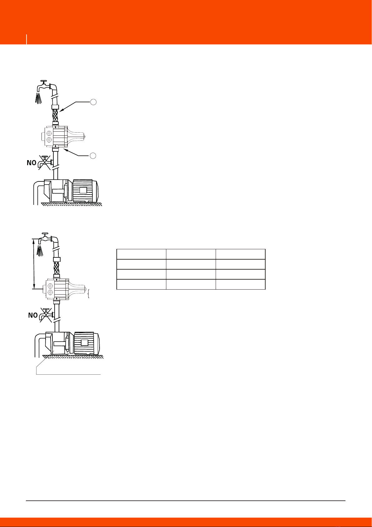
The control can be installed directly onthe pump or installed between
pump and the first tap. A pressure reducing valve must be installed on
the inlet of the control if pump's pressure exceeds 10 bar.
No taps can be installed between the pump and the control.
It is imperative to install the control with the arrows in the
upward position. (Fig 1/A)
It is advisable to connect the control outlet to the system by means
of a flexible pipe. (Fig 1/B)
Check suction and ensure that the pump is primed before starting the
control.
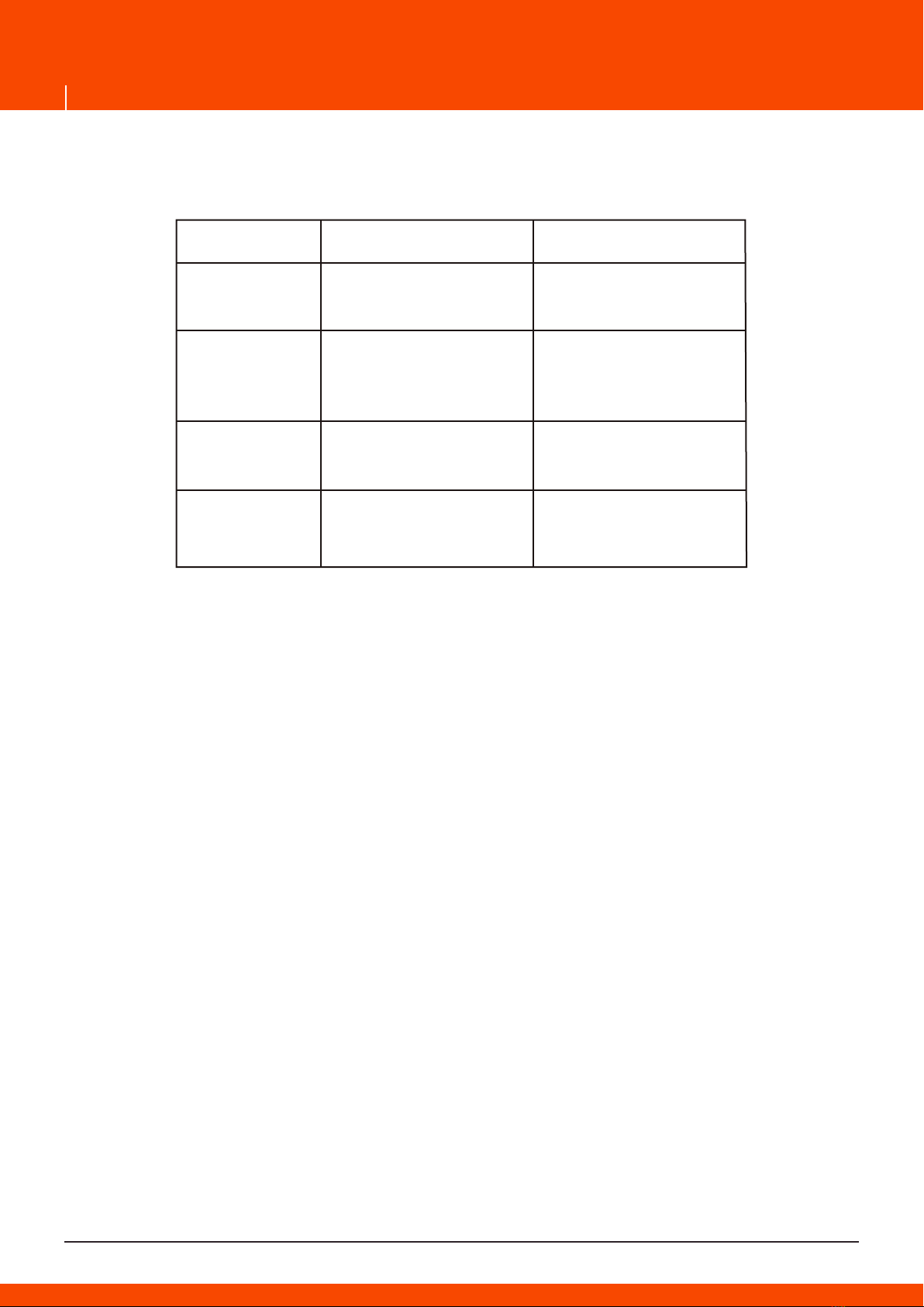
Normally pressure produced by the pump must be 1bar (0.1 MPa)
higher than the control's pre-set pressure, that is, checking on the
effective pressure of pump and system water column height
must be carried out according to the pre-set pressure.
The control's is set at its standard starting pressure
as 1.5bar (0.15 MPa) and starting pressure at 1.2 bar
or 2.2 bar are also available upon requests.
The pump can be blocked or continues to operate without stop if its
pressure is lower than stated minimum pressure. On the other hand,
the pump will not work if the height of water column exceeds above
standards. It is advisable to install the unit on a higher level to restore
a good installation condition as mentioned in the above or to change
for a unit with larger starting pressure.
2. STARTING AND WORKING
CAUTION: Never take the electronic board out of the control box. The wiring diagram inside the
terminal block will show you a correct connection. Wrong or loose connection will destroy the whole
electronic circuit.
Cable used for connection must be H05 or H07 type with 3×1.5 mm section .It shall have the outer
diameter at 8.9mm min. and 9.2 mm max. One of the leading end of the cable must be lower than
the position of the fixing screws while the cable being connected to the power as shown in the fig.
The six screws on the panel board and the two nuts for fixing cable must be well fastened to avoid
water entering into the control box and damaging the electronic circuit.
FUNCTION
The control is programmed to start and stop the pump operations automatically.
Its feature of water-shortage protection can protect the pump from being damaged during dry
running.
Except all ordinary function, It with timer can reset the pump automatically without water. When the
pump stop without water failed in the water supply system, the indicator light will be twinkled regu-
larly. In definite time, the controller reset pump every 15mins 1 time to test whether the water source
get right. If water source get right, the controller will exite this state. If in those time, no water suc-
tion, the control will keep without-water state, and after start the pump 4times every 15mins, the
control will reset pump in every 1h.Rectification of the failures that have caused the blockage allows
the system to be restarted by pressing the “restart” button for more than 2seconds. Keep button
“restart” pressed can stop the pump duringits operation and resume its work after stopping.
STARTING
When the control is connected to the electrical network, the green led “power on” lights up and the
yellow led “on”(pump in operation) lights 2-4 seconds later indicating that the pump has been
started. The pump continues to operate for 8 seconds enabling the system to fill in the pipes and to
reach the required pressure. If this lapse is insufficient, the red led “failure” lights up. In this event,
keep the “restart” button pressed and wait with a tap opened until the red led is off. Once the
button is released and the tap is closed, the control stops the pump at its max. Pressure.
3. WIRING DIAGRAMS FOR CONNECTING THE UNIT TO DIFFERENT KINDS OF PUMP’S
MOTORS
4. DEFECT DETECTING
5. AFTER SALES SERVICE
This control is guaranteed for a period of twelve months from the date of purchase and shall not be
subject to any claims caused by subjective misusing and disassemblies or any installations not in
accordance with the instruction.
6. TECHNICAL DATA
Power: 2.2 kW
Current: 30 A
Maximum working pressure: 10 bar
Max working temperature: 55ºC
Connection: 1"male - 1 1/4"male
Protection rating: IP65
1