HKC SW-1070 User manual

(for V3.3+ Software)
www.hkcsecurity.com
Security
Safe & Secure
SecureComm compatible
Installation Manual

Contents
WARNING
While this system has been designed to the highest standards it does
not offer guaranteed protection against burglary, fire or carbon
monoxide. Any alarm system is subject to compromise or failure to
activate for a variety of reasons. Therefore, good installation
practices and regular maintenance are essential to ensure continuous
satisfactory operation of the system. The transmission of text
messages is dependent on the SMS service provider. HKC Ltd.
cannot guarantee successful messaging. Messages which remain
undelivered when the validity period expires are discarded. The
validity period is the time the message is submitted plus 12 hours.
COPYRIGHT
Ó HKC Ltd. All Rights reserved. No part of this publication may be
reproduced, transmitted, stored in a retrieval system or translated in
another language in any form or by any means - electronic,
mechanical or otherwise without the prior written permission of
HKC Ltd.
DISCLAIMER
HKC Ltd. makes no representations or warranties with respect to the
contents hereof and specifically disclaim any implied warranties of
merchantability or fitness for any particular purpose. Further, HKC
Ltd. reserve the right to revise this publication and to make changes
from time to time in the contents hereof without obligation of HKC
Ltd. to notify any person of such revision.
This marking certifies that this product has been tested in a
representative system complying with the requirements laid
down in Electromagnetic Compatibility directive 2004/108/EC and
Low Voltage Directive 2006/95/EC and subsequent modifications.
PSTN Interface
This system has been designed to comply with the requirements of
eircom PSTN Interface Specification as required under article 4.2 of
The European Directive 1995/5/EC.
SW-1070 Installation Manual for V3.3 Software 260916_1
SW-1070 Overview....................................................................3
System Hardware: Remote Keypad...........................................5
RF-PIR....................................................................................12
RF-Contact/Sensor..................................................................15
RF-PIRCAM............................................................................18
RF-PIR-DT..............................................................................21
RF-Keyfob...............................................................................24
RF-Echo..................................................................................26
RF-SABB.............................................................................29
RF-SD (Smoke Detector).........................................................32
RF-HD (Heat Detector)............................................................34
RF-CO (Carbon Monoxide)......................................................36
Proximity Tag...........................................................................44
Zone Wiring.............................................................................45
Point ID Sensors......................................................................46
SW-1070 Panel / SABB Connections.......................................48
Service Menu...........................................................................56
Devices Menu..........................................................................60
Zone Menu..............................................................................62
Point Menu..............................................................................65
User Menu...............................................................................66
Timers Menu............................................................................68
System Options Menu..............................................................80
Comms Menu..........................................................................90
Digi Dialler ............................................................................92
GSM/GPRS........................................................................93
WiFi Module.........................................................................95
Monitoring & Voice...............................................................96
SMS Menu............................................................................99
Remote User Menu............................................................101
Panel Print Menu...............................................................102
Serial Port Equipment Menu.............................................103
Dialler Status LED..................................................................104
GSM Status LED....................................................................105
Technical Specifications........................................................106
Panel Defaults.......................................................................107
Digi Defaults..........................................................................108
Voice Library Words...............................................................109
Log Abbreviations..................................................................111
System Hardware: Main Panel...................................................7
Menu Navigation - Using Menu Keys..........................................8
Programming Menu...................................................................9
RF-PA (Panic Attack Button)....................................................38
RF-RKP...................................................................................41
SW-1070 Panel / 10-Zone Expander........................................49
SW-1070 Panel / Power Supply Unit.........................................51
SW-1070 Panel / Output Card..................................................53
Outputs Menu..........................................................................72
LAN Module (Ethernet Adapter)..........................................94
SecureComm Menu...........................................................103
Appendix A, BS 8243............................................................114
Appendix B, Configuration of Communication Devices..........117
Appendix C, Logical keys calculations & Access Levels..........121

3
PANEL
Wireless
- Easy to use install menu for wireless (RF) devices
- Devices include wireless... Contact/Inertia Sensor, PIR, PIRCAM, DualTech,
Keypad, Smoke Sensor, Heat Sensor, CO Sensor, PA Button, Internal Siren,
External Siren, Key-fob and Repeater
- Up to 70 wireless detectors (Contact/Inertia Sensors, Quad-PIR’s, PA Buttons
Smoke Sensors, Heat Sensors & CO Sensors)
- Up to 2 wireless Keypads
- Up to 2 wireless Internal Sirens and 2 wireless External Sirens
- Up to 64 wireless Key-fobs and 64 prox. tags mapped to Users.
- Up to 2 Repeaters (wired & wireless options available)
- Comprehensive RF device status menu (inc. signal strength & battery
capacity)
Zones
- All zones analysed
- All panel zones with dedicated alarm & tamper terminals
- Programmable zone descriptions
- Programmable zone wiring types; non EOL, single EOL & dual EOL loops.
- Zones 5, 6, 7 & 8 have ID sensor option
ID zones
- Up to 106 wired zones available with ID sensors, ID modules or ID PIR’s
- All ID modules with dedicated alarm & tamper terminals
- Programmable ID zone descriptions
Outputs
- 5 programmable outputs on main panel
- of which 3 are high current bell/strobe outputs
Other Features
- Resettable fuses
- Battery current monitoring and load test
- Enhanced engineer log; 999 events
- 8 block areas + 1 common area
- 2 part set areas per block with programmable descriptions and timers
- 2 serial ports and 1 USB (mini - B) port
KEYPAD
- Supports up to 8 keypads on high speed keypad bus
- Graphics LCD
- Audible word library
- 64 Users (max.); programmable user descriptions
- Built-in panic feature; pressing * and # buttons simultaneously
- RKP-SL = standard keypad, RKPX = proximity keypad, RF-RKP = wireless
keypad
The SW-1070 control panel comes with on-board SecureWave 2-way
wireless technology. It also has 10 on-board zones which can be expanded to 70
zones by using six 10 zone expanders or 106 wired inputs by using forty point devices.
The following features have been included in the panel....
SW-1070 Overview
Default Eng. Code - 4567 Default User Code - 1111 (Irl) 1234 (UK)

INTEGRATED POWER SUPPLY
- Switch Mode Power Supply (AC to DC)
- Using an integrated power MOSFET with EcoSmart® Adaptive Switching
- Loss of mains (EPS) detection
- Low back-up battery (Storage Device) voltage detection
- Short-circuit protection (resettable fuse)
- Overload protection
- Power Supply, Storage Device* and Control & Indicating Equipment are all
fully integrated with each other. Therefore, all monitoring and signalling are
directly handled by panel’s microprocessor.
RF-KEYFOB
- Arm/Disarm/Part-set via dedicated buttons
- Also secure Disarm via User Code
- Dedicated Duress button
GSM Unit
- Plugs-on to mother board
- Alternative GSM path (i.e. Backup line) to monitoring station
- Sends SMS text messages
- Receives SMS text commands to control system
- GPRS for realtime detection of jamming
- SecureComm variant available (GSM-SC)
Ethernet (LAN) Adapter
- Plugs-on to mother board
- IP access to your system
- Use with SecureComm
WiFi Adapter
- Plugs-on to mother board
- IP access to your system
- Use with SecureComm
4
SW-1070 Overview - continued
Default Eng. Code - 4567 Default User Code - 1111 (Irl) 1234 (UK)
* Storage device not supplied by HKC

NOTE: When preparing the cable for the keypad,
we recommend that the outer sheath be stripped
back by 100 - 130mm approx. This will allow the
keypad cover to open fully.
Also, strip back
about 5mm
from each core.
100mm - 130mm
Power
Fault
Alarm
Complies with
EN 50131 Grade 2 Class II
1
txt
4
ghi
7
pqrs
prev
PLAY
REC
LIGHT
QUIT
YES
NO
*
2
abc
5
jkl
8
tuv
0
[
3
def
6
mno
9
wxyz
#
next
Microphone
Zone for
prox tags
(RKPX only)
Speaker
Lid Screw
(behind flap)
LCD Display
Mounting
Hole
Not for
cable entry
Not for
cable entry
Not for
cable entry
To help strip-back sheath,
this is 130mm approx.
Mounting
Hole
Cable inlets
Cable inlets
Cable
Channel
Cable
Channel
NOTE: The RKP’s
tamper switch is
located here.
NOTE:
Preferred
routes for
cable
management
System Hardware: Remote Keypad
Default Eng. Code - 4567 Default User Code - 1111 (Irl) 1234 (UK) 5

Default Eng. Code - 4567 Default User Code - 1111 (Irl) 1234 (UK)
EXT
BELL
INT
BELL
STROBE
OUTPUTS
Aux
12V
REMOTE RKP/EXP
1+
+++ +B
-
--- -A
2
T
A
M
P
S
A
B
B
R
E
T
N
H
O
L
D
}
}
Programmable
Outputs
High-Current
Outputs
!
Tamper
Switch
+
B
-
A
Note: A maximum of 8 keypads and 6
expanders can be wired onto the system. Do
not draw in excess of the holding current of the
resettable fuses (see page 106); if necessary
use remote power supplies. When you use
remote power supplies, devices can be located
up to 1km from the panel (with CAT5 cable).
Otherwise, max. cable run from panel to keypad
= 150m and a total of 500m of cable can be
used.
System Hardware: Remote Keypad - continued
6

System Hardware: Main Panel
Default Eng. Code - 4567 Default User Code - 1111 (Irl) 1234 (UK)
Ext bell
Int bell Strobe Outputs Aux 12V Remote Keypad
1
+ + ++B
+---A
-- 2
TR BHO
Z6 Z7
Z1 Z5
Z2 Z3 Z4
Serial Port 1
Point
ID Bus
Point
ID Bus
Point
ID Bus
Point
ID Bus
Connection
to Power Supply
Connection for
Digi-Modem
}
}
}
}
}
}
}
}
Z8 Z10Z9
Antennas
Tamper Switch
Status LED
Radio
LED
Factory Default
Serial Port 2
JP1
J4 J3
Remote Keypad
(RKP) bus
Auxiliary 12V supply
Zone Inputs (Alarm and Tamper) from 1 to 10
USB
Port
Programmable
Outputs
Bell Hold-Off
Tamper
Return High-Current
Outputs
Useful Tips
For ease of installation you may
remove lid by pulling out the black
plastic hinges.
Always replace the mains fuse with
the rating indicated.
Always ensure that a good earth is
connected to the unit. This is
required to ensure compliance with
the EMC and LVD directives.
Isolate cables connected to panel
from high voltage cables.
Note: for
best RF
performance
keep wiring away
from antennas
Mains
Entry
Live
Cord
Grip
Neutral
Mains Fuse:
3.15A/250Vac
Anti-surge (T)
Protective
Cover for
Fuse Spur
Isolate mains before commencing any
maintenance on this unit.
After wiring mains, place protective
cover on fuse the spur.
The SW-1070
does not include a disconnect device to
isolate the mains supply. Please ensure
there is such a device fitted externally.
!
!Note: Red LED for internal purposes only
7
Earth

Default Eng. Code - 4567 Default User Code - 1111 (Irl) 1234 (UK)
Menu Navigation - Using Menu Keys
This section illustrates how to move around the menu structure in the SW-1070 control
panel. There are five menu keys used for menu navigation. The following diagram
describes their functions...
The next two pages contain the main areas of the programming menu...
When typing in zone
descriptions etc. the
cursor will move on to
the next letter after a
short period; just like
mobile phone texting.
QUIT
Used to exit a menu.
YES
Used to enter a menu.
Also used to enable an
option.
NO
Used to disable an
option.
NEXT
Used to move to the
NEXT item in a menu.
Used to move to the
PREVIOUS item in a menu.
PREV
MENU KEYS
1
txt
4
ghi
7
pqrs
prev
PLAY
REC
LIGHT
QUIT
YES
NO
*
2
abc
5
jkl
8
tuv
0
[
3
def
6
mno
9
wxyz
#
next
PLAY
QUIT
REC
YES
LIGHT
NO
prev
*#
next
1 1 $ · ! % & * ( )
2 a b c A B C 2 + =
3 d e f D E F 3 ; ?
4 g h i G H I 4 < >
5 j k l J K L 5 ` /
6 m n o M N O 6 - =
7 p q r s P Q R S 7
8 t u v T U V 8 + =
9 w x y z W X Y Z 9
0 space . , ' : - 0 @ #
CHARACTER SET
Key-in 4567 to access the Engineer Mode. This will need to be validated with a User
Code. To do this, key-in a valid User Code i.e. 1111 (or 1234 in the UK). You are now in
the Service Menu.
8

Programming Menu
Default Eng. Code - 4567 Default User Code - 1111 (Irl) 1234 (UK)
2 Devices Menu
1 Service Menu
3 Zone Menu
2 Wired Devices Menu
1 Add & Identify Devices
1 Zone Names
6 Default ID Bus
5 Default Expanders
7 Default RF
1 Default All
2 Default Users
3 Default Comms
1 RF Devices Menu
2 Locate Devices
2 Zone Types
3 Remove Devices
4 Keypad Config. Menu
5 Expander Options Menu
6 Remote Names Menu
7 Output Card Options
3 Zone Options
4 Zone Gross & Pulse
5 Zone Hardware
6 Zone Block Assign
7 Technical Zone Options
8 Zone Map menu
4 Point Menu
6 Timers Menu
Please turn over
for...
5 Users Menu
1 Point Names
1 Set Time & Date
5 Event Timers
6 Smart Lights
7 Smart Doors
4 Block Timers
1 User Codes
2 Point Types
2 System Timers
2 User Names
3 Point Options
3 Miscellaneous Timers
3 User Options
4 Point Gross & Pulse
5 Point Block Assign
6 Point Map Menu
4 Engineer Code
5 User Block Assign
6 User Prox Assign
7 Manufacturer’s Code
1 Never Log NO
01 Non EOL
1 Zone Name Text
1 Point Name Text
1 Mapped Outputs
1 Mapped Outputs
1 Entry Timers
2 Only Log at Setting NO
02 Single EOL
2 Zone Audio
2 Point Audio
2 Mapped Output Options
2 Mapped Output Options
2 Exit Timers
3 Internal Bell Timers
4 External Bell Timers
3 Show Open before Set NO
03 Dual EOL 4K7
0X Dual EOL 2K2
4 Inhibit Required NO
0X Point ID
0X RF Device
0X RFI Device
dd/mm/yy hh:mm
1 Weeks to Service 00
1 Internal Bell 15
2 Fire Exit Delay 00
3 Mains Fault Delay 55
2 External Bell 15
3 Strobe Time 00
4 Entry Time 30
5 Exit Time 30
6 Split Entry Time 30
7 Soak Period 00
8 Bell Delay 00
9 Double Knock Reset 05
0 Double Knock Open 10
USER OPTIONS
EVENT TIMER TYPES
Full Set User Menu
Unset Manager Menu
Inhibit Output Only
Part Set A 24 Hour
Part Set B Code & Prox
Unused Auto-Arm Part Set A
Open/Closed Auto-Arm Part Set B
Home Alone Timed Access
Auto-Activate User Alert
Auto-Arm Full
2 Battery Load Test
2 Full Set ?
2 Log Menu
1 Unset ?
1 System Overview
4 Default Wired Keypads
3 Quick Arm ?
3 Engineering Tools Menu
4 Part Set A ?
4 Engineer Arm/Disarm
5 Part Set B ?
5 Defaults Menu
7 Voice Demo Menu
8 Remote Service
1 Battery Current Monitor
2 Test Digi Channels
3 Test Extended Reports
1 Test Outputs
8 Battery Menu
9 Bell Test
10 Zone Resistance
5 RF SABB Status
6 RF Wand Status
7 RF Keypad Status
1 RF Device Status 1 RF Zone Status
1 Image Size
2 RF Point Status
2 Colour
2 Open Inputs Menu
3 Walk Test Menu
4 Show System Faults 3 RF Keyfob Status
3 Number of Images
5 Test Outputs & Channels
6 Test RF Devices
7 Show Software Versions
4 RF Echo Status
4 Live Images
1 Add & Identify RF Devices
2 Locate RF Devices
3 Remove RF Devices
4 RF Device Options
5 RF System Options
6 RF Camera Options
Inhibit
Access
Excl. from Part Set A
Excl. from Part Set B
Double Knock
Soak
Chime
24 Hour
Perimeter
Remote Test
Inhibit
Excl. from Part Set A
Excl. from Part Set B
Soak
Chime
Disable BV
Remote Test
Inhibit
Soak
Silent PA
Remote Test
Inhibit
Soak
Remote Test
Soak
Key Pulse
Remote Test
Inhibit
Soak
24 Hour
Fire Exit Delay
Remote Test
None
Remote Test
Unset
Remote Test
Inhibit
Soak
24 Hour
Remote Test
ZONE/POINT TYPES vs OPTIONS
Alarm
Entry / Exit
Panic
Fire
Tamper
Gas
Key
Key Partset A
Key Partset B
Fire Exit
Exit Terminator
Shunt Lock
Line Fault
Fail To Communicate
Technical
ZONE & POINT TYPES
Alarm
Entry/Exit
Panic
Fire
Tamper
Key
Line Fault
Fail to Connect
Unused
Technical 1
.. ..
Technical 8
Exit Terminator
Gas
Shunt Lock*
*UK only
Fire Exit 1
.. .. ..
Fire Exit 12
Key Part Set A
Key Part Set B
MAPPED OUTPUT OPTIONS
Unset Disable Y/N Latched Output Y/N
Pulsed Output Y/N Output Trip Time (sec)
TR
ZONE 2
6 Firmware Upgrade
8 System Options
Menu
9 Comms Menu
9
For adjusting RF-PIR sensitivity,
activating/deactivating the MC’s in
RF-Contact/Sensors, turning on
the “Unset via User-code” feature
on the key-fob, adjusting the RF-
Echo volume, controlling the flash
on the RF-PIRCAM etc.
Programming Menu - Continued
Default Eng. Code - 4567 Default User Code - 1111 (Irl) 1234 (UK)
7 Output Menu 1 Panel Outputs
3 PSU Outputs
4 Output Card Outputs
5 Output Groups
6 User Outputs
2 Expander Outputs
5 Partset Options Menu
8 System Options
Menu
9 Comms Menu
1 Final Door Set NO
2 Exit Fault Bell YES
3 Line Fault Bell NO
4 Inhibit Tamper NO
5 Forced Arm YES
6 Display Armed YES
7 Extend Block Exit Time NO
8 Rearm Always NO
10 Arm Squawk NO
11 Infinite Exit NO
9 Rearm Count 3
1 Arming Options Menu
2 Unset Options Menu
3 Quick Key Menu
4 Keypad PA Options Menu
6 Miscellaneous Options Menu
7 Audio Options Menu
8 Edit Miscellaneous Text
9 Garda Policy Option
9 BS8423 Options (UK only)
(UK only)
1 User Walk Test YES
2 Fire Output Enabled YES
5 Fire Exit Require Code YES
6 Tamper Rearm YES
3 Extend Block Entry Time NO
4 Fire Exit Bells NO
1 Quick # Key Menu
1 Keypad * & # PA YES
1 Mains Fault Buzzer YES
1 Output Names
1 Pre-Alarm YES
1 Police Options
2 Quick Key Menu
2 Keypad PA Silent NO
2 Line Fault Buzzer YES
2 Output Options
2 Bell Tamp: Verified Alarm NO
2 Technistore Options
3 Silent PA Line Fault YES
3 FTC Buzzer YES
4 Fault Alert Buzzer NO
3 Alarm Abort Time 00
4 Restricted Indication YES
1 Timed Soak NO
1 Part Set A Exit Time NO
1 Edit Installer’s Name
2 Edit Block Names
2 Engineer Lock NO
2 Part Set B Exit Time YES
3 Duress Codes NO
3 Access to Exit Entry NO
3 Edit Part Set A Text
4 Walk Test Bell NO
4 Part Set Digi Alarm YES
4 Edit Part Set B Text
5 System Double Knock NO
6 Part Set A Exit Buzzer NO
8 Part Set A Entry/Exit to Alarm NO
9 Part Set B Entry/Exit to Alarm NO
6 Latch Chime NO
7 Part Set B Exit Buzzer YES
7 Internal Bell Chime NO
5 Indicate Part Set YES
5 Edit Fire Exit Message
6 Edit Fire Exit Type
7 Edit Technical Type
8 Edit Site Name
8 Auto Hour Change YES
9 Work to EN 50131 YES
10 Silent Fire NO
QUICK KEY MENU
0#1 User Log 0*1 SMS Engineers
0#3 Walk Test 0*2 SMS Log
0#4 Full Arm 0*3 Call PC
0#5 Quick Arm 0*4 PC Direct
0#6 Toggle Chime 0*5 User Check
0#7 Part Set A 0*6 Temporary User
0#8 Part Set B 0*7 Home Alone
0#9 Bell Test 0*8 Outputs
01 Pre-alarm
1 PSU51 Outputs
1 OPC51 Outputs
1 EXP1 Outputs
-ve
+ve
+ve
02 Alarm
05 External Bell
20 PSU85 Outputs
20 OPC85 Outputs
13 EXP13 Outputs
.. .. ..
.. .. ..
.. .. ..
.. .. ..
OUTPUT OPTIONS
Light
Partguard
Latch
Fire Reset
Perimeter
Tamper
Buzzer
Trouble
Tech 1
.. ..
Tech 8
Fire Exit 1
.. .. ..
Fire Exit 12
Block 1 Buzzer
.. .. ..
Block 8 Buzzer
Pre-Alarm
Block 1 Pre-Alarm
.. .. .. ..
Block 8 Pre-Alarm
Alarm Abort
Block 1 Alarm Abort
.. .. .. ..
Block 8 Alarm Abort
Mains Delay
Unexpected Open
Unexpected Close
Auto-activate
User Alert
SmartLight
SmartDoor
Unused
*UK only
Line Fault
Inhibit
B0 Inhibit
.. ..
B8 Inhibit
Force GSM
Zone/Point MAP
Pulse Gate
Heat
Gates
Aux
Free to Use
Panic Confirmed*
Sensor Reset
Internal Bell
External Bell
Alarm
Arm /Disarm
Fire
Panic Alarm
Strobe
B1 Alarm
.. ..
B8 Alarm
B0 Arm/Disarm
.. .. ..
B8 Arm/Disarm
B1 Internal Bell
.. .. ..
B8 Internal Bell
B1 External Bell
.. .. ..
B8 External Bell
B1 Strobe
.. ..
B8 Strobe
2 Communicators
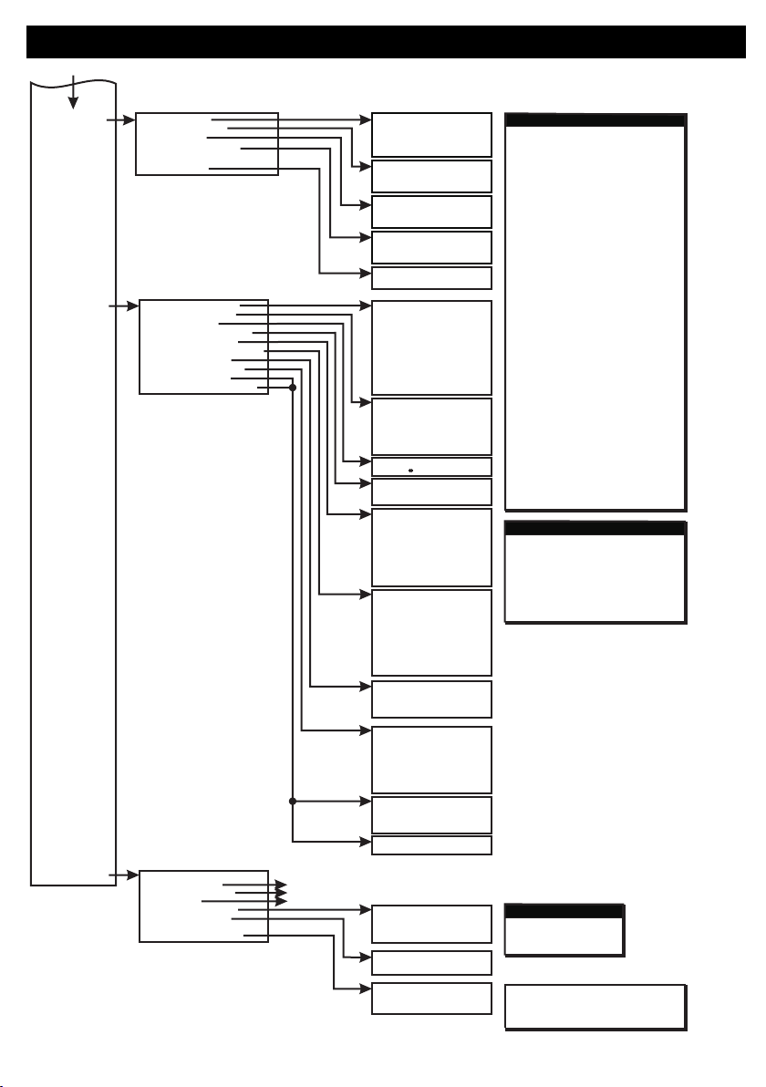
1 Comms Overview
See next page
See next page
See next page
3 Monitoring & Voice
4 SMS Menu
5 Remote User Menu
6 Panel Print Menu
7 Serial Port Equip. Menu
8 SecureComm Menu
1 Remote User Codes
2 Remote User Names
3 Remote User Options
4 Remote User Phones
1 Print Engineer Log
2 Printer Options
1 Status
2 Disable
3 Options
4 Printer Port
REMOTE USER OPTIONS
Call Back
Remote Set
Remote Unset
NO
NO
NO
Default Engineer Code - 4567
Default User Code (IRL) - 1111
Default User Code (UK) - 1234
From previous page
10

Programming Menu - Continued
Default Eng. Code - 4567 Default User Code - 1111 (Irl) 1234 (UK) 11
1 Status
1 Status
1 Status
1 Phone Numbers
1 Monitor Signal YES
1 Enabled NO
1 Enabled NO
1 DHCP Enabled YES
1 DHCP Enabled YES
1 Answer Calls NO
1 Enable SMS YES
1 PIN Code
1 IP Settings
1 IP Settings
2 Disable GSM
2 Disable Module
2 Disable Module
1 Line Share NO
2 Fault Delay 05m
2 Encryption NO
2 Encryption NO
2 IP Address
2 IP Address
2 Use Caller ID NO
2 Server Number
2 Signal Monitor
2 SmartLink IP
2 SmartLink IP
3 Incoming Calls
3 Options
3 Advanced Options
3 Scan for WiFi
4 Advanced Options
2 PABX Prefix
2 Rings Before Answer 00
3 Jam Detect YES
3 Password
3 Password
3 Subnet Mask
3 Subnet Mask
4 Gateway
4 Gateway
5 DNS Server
5 DNS Server
1 Phone Menu
1 Digi Dialer
1 Line Monitor
1 Status
1 Line Monitor On YES
1 Dial Tone YES
2 GS/GPRS
3 LAN/WiFi
2 Dial Options
2 Disable Dialer
2 Off-hook Monitor NO
3 Incoming Call Options
3 Options
3 Off-hook/LF/Unset NO
4 SMS Options
1 AVI Time 30s
1 Channel Types
1 Phone Reports
1 Record Site Name
1 Site Line 1
1 Test Start hh:mm
1 Test Start hh:mm
2 Phone Accounts
2 AVI Message
2 Channel Options
2 Block Reports
2 Play Site Name
2 Site Line 2
2 Test Period 000h
2 Test Period 000h
3 Phone Protocols
3 AVI Audio NO
P01 Report Alarm
e.g. P01 087 1234 etc.
e.g. P01 J SMITH
e.g. P01 USER or ENGINEER
e.g. 1 MAIN STREET
YES
NO
NO
NO
NO
NO
NO
NO
NO
2 Phone Menu
1 Dual Report NO
1 SMS Attempts 12
1 Phone Number
3 Channel Menu
P01 Report System Fault
1 Site Name
2 5 Second Interval NO
2 Max SMS Messages 07
2 Phone Name
4 Reports Menu
P01 Report Arm
4 Options
3 Max Attempts 12
3 SMS Alarm Delay 00s
3 Phone Type
5 Voice Site Name
P01 Report Inhibit
5 Test Messages
4 FTC Attempts 03
4 SMS Commands YES
5 SMS Caller ID NO
4 Phone Options
7 AVI Menu
P01 Report Technical Zone
8 Options
P01 Report Fire Exit
2 Make Test Call
P01 Report Device
P01 Report Test
6 Test Call Menu
P01 Report Soak
3 Send Test Text
5 Retry Period 60m
5 Phone Block Assign
Communicators
Monitoring & Voice
LAN
WiFi
OR
SMS Menu

Tamper
Switch
For Mounting
Bracket
Mounting
Holes
Mounting
Hole
Release
Tag for
Circuit
Assembly
Battery
LED
Antenna
Pyro
Sensor
+
-
LITHIUM
BATTERY
CR123A 3V
RF-PIR
2 Devices Menu
2 Wired Devices Menu
1 Add&Id:RF Zones
2 Add&Id:RF Keyfob
3 Add&Id:RF Echo
1 RF Devices Menu
1 Add & ID RF Devices Scanning RF Devs
1 Add & ID RF Devices
2 Locate RF Devices
2 Locate RF Devices
3 Remove RF Devices
3 Remove RF Devices
1 Service Menu
3 Zone Menu
• To put an RF-PIR on to a SW-1070 system go into engineer mode.
• Open the RF-PIR and pull the isolator away from the battery - this powers it up.
• If you have a number of RF-PIRs you can open them too at this stage and remove their isolators.
• Don’t close their lids just yet.
• Select the Devices Menu. Then RF Devs Menu. Next select the Add & Id RF Devs option.
• Next, add and identify the RF-PIR as a zone.
• The system displays Devs Found - 000 when it starts scanning and as it finds its first device the display will
change to Devs Found - 001. When the system has found all its devices, press
• Next, close the devices’ tamper switches by fitting their lids.
• As you close the devices’ tamper switches in sequence. You will hear an audible indication as each device
is identified into the system
Note: The RF-Echo can have a delayed reaction.
PLAY
QUIT
Default Eng. Code - 4567 Default User Code - 1111 (Irl) 1234 (UK)
LED
Diffuser
Custom
Fresnel
Lens
Add & ID on to the System
• 15m Detection
• Recommend that battery is changed every 3 years
• >400m Line-of-sight Radio Range
• Close-in Detection
• Adjustable Sensitivity
• Noise Immunity
• Temperature Compensation
!
12

RF-PIR - Continued
1 Add & ID RF Devices
1 Add & ID RF Devices
1 Add & ID RF Devices
1 Add & ID RF Devices
1 Add & ID RF Devices
1 Add & ID RF Devices
1 RF Zone Opts
1 Locate: RF Zone
1 Remove: RF Zone
Z01 Zone 1
Z01 Zone 1
Z01 Zone 1
2 RF Keyfob Opts
2 Locate: RF Keyfob
2 Remove: RF Keyfob
Z02 Zone 2
Z02 Zone 2
Z02 Zone 2
2 Locate RF Devices
2 Locate RF Devices
2 Locate RF Devices
2 Locate RF Devices
2 Locate RF Devices
2 Locate RF Devices
3 Remove RF Devices
3 Remove RF Devices
3 Remove RF Devices
3 Remove RF Devices
3 Remove RF Devices
3 Remove RF Devices
4 RF Device Options
4 RF Device Options
4 RF Device Options
4 RF Device Options
4 RF Device Options
4 RF Device Options
• Go to the Devices Menu. Then RF Devs Menu. Next select the RF Device Options.
• Go to the Devices Menu. Then RF Devs Menu. Next select the Locate RF Devices.
• Go to the Devices Menu. Then RF Devs Menu. Next select the Remove RF Devices.
• The RF-PIR’s programmable options can be accessed as follows;
• The RF-PIR can be located as follows;
• The RF-PIR can be removed as follows;
• From there go to RF Zone Opts and then select the RF-PIR number in question.
• You can now select the sensitivity of the RF-PIR i.e. Setting MED is for the medium sensitivity.
• There are three levels: LOW, MED and HI.
• The other option is Mon Sup (Monitored Supervisory signal) is defaulted to YES. When the device is “lost” for
a prolonged period of time, a supervisory alarm is flagged by the panel. This can be turned off by selecting NO.
However, we recommend that this feature is left as YES
• From there go to Locate: RF Zone and then select the RF-PIR number in question.
• The LED on the RF-PIR that you selected will flash on and off every second thus helping you to locate it.
• Also note, opening & closing the tamper switch on a device will locate and display said device at the keypad.
• From there go to Remove: RF Zone and then select the RF-PIR number you want removed. Press YES to
select this device for removal and press YES again to confirm removal.
2 Devices Menu
2 Devices Menu
2 Devices Menu
2 Wired Devices Menu
2 Wired Devices Menu
2 Wired Devices Menu
1 RF Devices Menu
1 RF Devices Menu
1 RF Devices Menu
1 Service Menu
1 Service Menu
1 Service Menu
3 Zone Menu
3 Zone Menu
3 Zone Menu
Default Eng. Code - 4567 Default User Code - 1111 (Irl) 1234 (UK) 13

RF-PIR - Continued
Range of Detection
Specifications
2m 2m
2.4m 2.4m
2m
4m
6m
8m
10m
14m
2m
4m
6m
8m
2m
4m
6m
8m
Vertical Coverage
Vertical Coverage
Horizontal Coverage
12m
1m 1m
2m
4m
6m
8m
10m
12m
14m
10m
2m
2m
4m
(close-in detection)
(close-in detection)
Horizontal Coverage
Note: mount the unit 2.4m from the ground
Current Consumption
Battery Life
Range
Frequency
Temperature
Mounting Height
Weight
Dimensions
EN 50131-2-2
3Vdc nom. • 1400mAh • size 2/3A
Standby: 8µA
Transmit: 40mA (peak)
Typically >3 years
Line-of-sight > 400m
868Mhz
2.4m
-10°C to +40°C
W=64mm H= 117mm D = 53mm
155g (including battery)
Grade 2 Class II
Battery
Default Eng. Code - 4567 Default User Code - 1111 (Irl) 1234 (UK)
14

RF-Contact/Sensor
Mounting
Holes
Mounting
Hole
Mounting
Hole
Sensor
Head
Mounting
Hole for
Pry-off
Tamper
These ribs
indicate
Centre Mark
of Magnet
Tamper
Switch
Tamper
Loop
Alarm
Loop
Battery
Antenna
Status
LED
+
-
LITHIUM
BATTERY
CR123A 3V
• Recommend that battery is changed every 3 years
• >400m Line-of-sight Radio Range
• MC Switches (Reeds) on Left and Right
• Optional Inertia Sensor Version
• Adjustable Sensitivity on Inertia Sensor
• RF-CW = (magnetic Contact in white) and RF-CB = (magnetic Contact in brown)
• RF-CSW = (MC & inertia Sensor in white) and RF-CSB = (MC & inertia Sensor in brown)
2 Devices Menu
2 Wired Devices Menu
1 Add&Id:RF Zones
2 Add&Id:RF Keyfob
3 Add&Id:RF Echo
1 RF Devices Menu
1 Add & ID RF Devices Scanning RF Devs
1 Add & ID RF Devices
2 Locate RF Devices
2 Locate RF Devices
3 Remove RF Devices
3 Remove RF Devices
1 Service Menu
3 Zone Menu
• To put an RF-Cx or RF-CSx on to a SW-1070 system go into engineer mode.
• Open the RF-Cx or RF-CSx and pull the isolator away from the battery - this powers it up.
• If you have a number of devices you can open them too at this stage and remove their isolators.
• Don’t close their lids just yet.
• Select the Devices Menu. Then RF Devs Menu. Next select the Add & Id RF Devs option.
• Next, add and identify the RF-Cx or RF-CSx as a zone.
• The system displays Devs Found - 000 when it starts scanning and as it finds its first device the display will
change to Devs Found - 001. When the system has found all its devices, press
• Select zone number to be added & Id’ed.
• Next, close the devices’ tamper switches by fitting their lids.
• As you close the devices’ tamper switches in sequence. You will hear an audible indication as each device
is identified into the system
Note: The RF-Echo can have a delayed reaction.
PLAY
QUIT
Add & ID on to the System
!
Default Eng. Code - 4567 Default User Code - 1111 (Irl) 1234 (UK) 15
C
L

RF-Contact/Sensor - Continued
Default Eng. Code - 4567 Default User Code - 1111 (Irl) 1234 (UK)
16
1 Add & ID RF Devices
1 Add & ID RF Devices
1 Add & ID RF Devices
1 Add & ID RF Devices
1 Add & ID RF Devices
1 Add & ID RF Devices
1 RF Zone Opts
1 Locate: RF Zone
1 Remove: RF Zone
Z01 Zone 1
Z01 Zone 1
Z01 Zone 1
2 RF Keyfob Opts
2 Locate: RF Keyfob
2 Remove: RF Keyfob
Z02 Zone 2
Z02 Zone 2
Z02 Zone 2
2 Locate RF Devices
2 Locate RF Devices
2 Locate RF Devices
2 Locate RF Devices
2 Locate RF Devices
2 Locate RF Devices
3 Remove RF Devices
3 Remove RF Devices
3 Remove RF Devices
3 Remove RF Devices
3 Remove RF Devices
3 Remove RF Devices
4 RF Device Options
4 RF Device Options
4 RF Device Options
4 RF Device Options
4 RF Device Options
4 RF Device Options
• Go to the Devices Menu. Then RF Devs Menu. Next select the RF Device Options.
• Go to the Devices Menu. Then RF Devs Menu. Next select the Locate RF Devices.
• Go to the Devices Menu. Then RF Devs Menu. Next select the Remove RF Devices.
• The RF-Cx or RF-CSx programmable options can be accessed as follows;
• The RF-Cx or RF-CSx can be located as follows;
• The RF-Cx or RF-CSx can be removed as follows;
• From there go to RF Zone Opts and then select the RF-Cx or RF-CSx number in question.
• You can now turn off the devices’ magnetic contacts (otherwise known as reed switches).
• Selecting Reeds ON NO .turns them off.
• The other option is Mon Sup (Monitored Supervisory signal) is defaulted to YES. When the device is “lost” for
a prolonged period of time, a supervisory alarm is flagged by the panel. This can be turned off by selecting NO.
However, we recommend that this feature is left as YES
• From there go to Locate: RF Zone and then select the RF-Cx or RF-CSx number in question.
• The LED on the RF-Cx or RF-CSx that you selected will flash on and off every second thus helping you to
locate it.
• Also note, opening & closing the tamper switch on a device will locate and display said device at the keypad.
• From there go to Remove: RF Zone and then select the RF-Cx or RF-CSx number you want removed. Press
YES to select this device for removal and press YES again to confirm removal.
2 Devices Menu
2 Devices Menu
2 Devices Menu
2 Wired Devices Menu
2 Wired Devices Menu
2 Wired Devices Menu
1 RF Devices Menu
1 RF Devices Menu
1 RF Devices Menu
1 Service Menu
1 Service Menu
1 Service Menu
3 Zone Menu
3 Zone Menu
3 Zone Menu

Default Eng. Code - 4567 Default User Code - 1111 (Irl) 1234 (UK) 17
RF-Contact/Sensor - Continued
!
!
!
!
Notes:
For best RF performance keep wiring away from antenna.
Only use 1 magnet per device.
Reed switches are active by default.
RF-Cx are known as RF-Contact and RF-CSx are known as RF-Inertia (even
though they have magnetic contacts too). The “x” suffix can be either W for white or
B for Brown
Current Consumption
Battery Life
Range
Frequency
Temperature
Weight
Main Dimensions
Magnet Dimensions
EN 50131-2-6
3Vdc nom. • 1400mAh • size 2/3A
Standby: 7µA
Transmit: 40mA (peak)
Typically >3 years
Line-of-sight > 400m
868Mhz
-10°C to +40°C
W=33mm H= 122mm D = 33mm
W=10mm H= 41mm D = 15mm
80g (including sensor head, battery & magnet)
Grade 2 Class II
Battery
Specifications
• Additional wired MC’s can wired into the system via the
Alarm/Tamper terminals. Note though, the length of the tamper
loop in this scenario is limited (100m for Alarm loop and 3m for
Tamper loop)
Tamper
Loop
Alarm
Loop
+
-
LITHIUM
BATTERY
CR123A 3V
Mounting
Holes
• Ensure that the inertia sensor head arrow is vertical.
• The sensor head has its own specific holder. Use the
screw holes in this holder when mounting the unit to
increase its responsiveness to vibrations.

Default Eng. Code - 4567 Default User Code - 1111 (Irl) 1234 (UK)
RF-PIRCAM
Mounting
Holes*
Custom
Fresnel
Lens
Camera Lens
Light Sensor
Flash
LED Difuser
Release
Tag for
Circuit
Assembly
+
-
+
ULTRA LITHIUM
+
-
+
ULTRA LITHIUM
Battery
Antenna
LED
Camera
Assembly
Tamper
Switch
Pyro
Sensor
Battery
• 15m Pyro Detection
• High Quality Colour Camera with white LED for low light
• Very Low Current Consumption
• Long Battery Life (typically up to 3 years)
• >400m Line-of-sight Radio Range
• Close-in Detection
• Adjustable Sensitivity
• Noise Immunity
• Temperature Compensation
2 Devices Menu
1 Add & ID RF Devices
2 Locate RF Devices
3 Remove RF Devices
1 Service Menu
3 Zone Menu
• To put an RF-PIRCAM on to a SecureWave system go into engineer mode. Select the Devices Menu, then
RF Devs Menu. Next, select the Add & Id RF Devs option.
• Now you have a choice to add and identify the RF-PIRCAM and map it onto either a zone or point location.
Tip: To conserve zones it would be best to add and ID your RF-PIRCAMs onto Points (of which there are 40)
first before you assign them to Zones.
• The system displays Devs Found - 000 when it starts scanning and as it finds its first device the display will
change to Devs Found - 001. When the system has found all its devices you will be prompted to close the
devices’ tamper switches.
Note: A full scan will take about a minute and
•Close the devices’ tamper switches in sequence. You will hear an audible indication as each device is
identified into the system
Note: The RF-Echo can have a delayed reaction.
may be halted at any time by pressing PLAY
QUIT
2 Wired Devices Menu
1 RF Devices Menu
!RF-PIRCAM does not connect to RF-Repeater
Add & ID on to the System
1 Add&Id:RF Zones
2 Add&Id:RF Points
1 Add & ID RF Devices Scanning RF Devs
Scanning RF Devs
2 Locate RF Devices
3 Remove RF Devices
18

Default Eng. Code - 4567 Default User Code - 1111 (Irl) 1234 (UK)
RF-PIRCAM - Continued
2 Devices Menu
2 Wired Devices Menu
1 RF Devices Menu
1 Add & ID RF Devices
1 Add & ID RF Devices
1 Image Size
2 Color
3 Num Images
4 Live Images
2 Locate RF Devices
2 Locate RF Devices
3 Remove RF Devices
3 Remove RF Devices
4 RF Devs Options
5 RF System Options
6 RF Camera Options
4 RF Devs Options
1 Service Menu
3 Zone Menu
• To get to either the RF-Zones or RF-Points options menu; select the Devices Menu. Then RF Devs Menu.
Next select the RF Devs Options.
• The RF-PIRCAM’s programmable options can be accessed as follows;
• From there go to either the RF Zone Opts or RF Point Opts menu and then select the RF-PIRCAM number
in question.
• You can now select the sensitivity of the RF-PIRCAM. The three levels are LOW, MED and HI.
• Another option is Mon Sup (Monitored Supervisory signal) is defaulted to YES. When the device is “lost” for
>120 minutes, a supervisory alarm is flagged by the panel. This can be turned off by selecting NO. However,
we recommend that this feature is left as YES
• The final section is Flash. There are three conditions; ON, OFF and AUTO. The default is ON - this means
that the RF-PIRCAM always triggers the flash when it takes an image. With OFF there is no flash (unless you
are taking a live snapshot) and with AUTO, the flash is only triggered when the room is dark.
• There are 4 sections to the RF Camera Opts menu...
2 Mon Sup YES
1 Settings MED
3 Flash ON
1 Add & ID RF Devices
1 RF Zone Opts
2 RF Point Opts
2 Locate RF Devices
3 Remove RF Devices
4 RF Devs Options
• Image Size is defaulted to VGA which is 640x800 pixels. If you press NO you can select QVGA which has a
lower resolution of 320x240 pixels but has a quicker transmission time.
Color is defaulted to YES. You can select black and white by pressing NO but unless there are specific site-
related reasons for choosing black and white we recommend keeping the colour on.
Num images is shorthand for “Number of images” and is defaulted to 3. When the system is armed and the
PIRCAM is triggered, 3 snapshots are taken at 1 second intervals. This number can be changed by pressing
YES and then pressing any number between 1 to 5.
• Live images is defaulted to NO. When YES is selected, you can take a snapshot on your smart phone
whenever you want
•
•
!To utilise the camera, the system needs to be connected to SecureComm and have the HKC app
2 Wired Devices Menu
1 RF Devices Menu
PIR located -LED turns on/off every second
• In the Locate: RF Zones or Locate: RF Points you will observe the following;
Note: To locate an RF-PIRCAM go to the Devices Menu in engineer mode and follow menu path below...
• You will automatically be brought to either zone 1 or the first point (P50)
• When you want to move on to the next zone or point then press
1 Locate:RF Zones
2 Locate:RF Points
1 Add & ID RF Devices
2 Locate RF Devices
3 Remove RF Devices
#
next
19

Default Eng. Code - 4567 Default User Code - 1111 (Irl) 1234 (UK)
RF-PIRCAM - Continued
2 Wired Devices Menu
1 RF Devices Menu
• To remove an RF-PIRCAM go to the Devices Menu in engineer mode and follow menu path below.
• You will automatically be brought to either zone 1 or the first point (P50)
• Go to the zone or point you want to remove and press
1 Remove:RF Zones
2 Remove:RF Points
1 Add & ID RF Devices
2 Locate RF Devices
3 Remove RF Devices
REC
YES
Note: mount the unit 2.4m from the ground
2m 2m
2.4m 2.4m
2m
4m
6m
8m
10m
14m
2m
4m
6m
8m
2m
4m
6m
8m
Vertical Coverage
Vertical Coverage
Horizontal Coverage
12m
1m 1m
2m
4m
6m
8m
10m
12m
14m
10m
2m
2m
4m
(close-in detection)
(close-in detection)
Horizontal Coverage
User warning: Do not partially or completely obscure the detector’s field of view.
!
Range of Detection
Specifications
PIR Current Consumption
Camera Current Consumption
Battery Life
Camera
Radio Range
Frequency
Temperature
Mounting Height
Weight
Dimensions
Two Lithium 3Vdc (nom.) 1,400mAh
Standby: 8µA
Transmit: 55mA (peak)
Standby: 5µA
Active: 500mA (peak)
Typically up to 3 years
Full colour VGA
868Mhz
2.4m
-10°C to +40°C
W=64mm H= 136mm D = 53mm
210g (including batteries)
Grade 2 Class II
Line-of-sight > 400m
Battery
EN 50131-2-2
20
Other manuals for SW-1070
1
Table of contents
Other HKC Control Panel manuals


