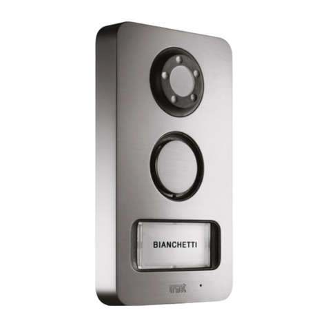
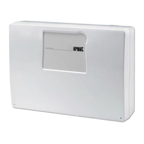
urmet domus 1067/032 Owner's manual

DS1067-035A LBT8633
Mod.
1067
BUS CONTROL PANEL 8/32 INPUTS
Ref.1067/032
Ref.1067/042
PROGRAMMING MANUAL

DS1067-035A 2LBT8633
TABLE OF CONTENTS
1PREFACE................................................................................................................................................. 6
1.1 NAVIGATION THROUGH MENUS ............................................................................................. 6
2COMMAND DEVICES.............................................................................................................................. 8
2.1 1067/021 DISPLAY KEYPAD ...................................................................................................... 8
2.2 ELECTRONIC KEY READER 1067/334–1067/335 AND PROXIMITY READER 1067/434 –
1067/435................................................................................................................................................... 9
2.3 1058/035 REMOTE CONTROL................................................................................................... 9
2.4 SYSTEM STATUS INFORMATION........................................................................................... 10
2.4.1 System status display......................................................................................................................... 10
2.4.2 Open inputs display............................................................................................................................ 10
2.4.3 Excluded inputs display...................................................................................................................... 10
2.4.4 Examine alarm and tamper memory .................................................................................................. 10
2.4.5 Alarm and tamper memory deleting ................................................................................................... 10
2.4.6 Display failures and faults .................................................................................................................. 10
3ALARMS, EVENTS AND SIGNALLING................................................................................................. 11
3.1 DESCRIPTION OF ALARMS, EVENTS.................................................................................... 11
3.1.1 Burglar Alarm ..................................................................................................................................... 11
3.1.2 Pre-alarm ........................................................................................................................................... 11
3.1.3 Tamper alarm..................................................................................................................................... 12
3.1.4 Wrong code alarm.............................................................................................................................. 12
3.1.5 Panic alarm ........................................................................................................................................ 13
3.1.6 Silent panic alarm............................................................................................................................... 13
3.1.7 Hold-up alarm..................................................................................................................................... 13
3.1.8 Emergency alarm ............................................................................................................................... 14
3.1.9 Fire alarm ........................................................................................................................................... 14
3.1.10 Fire reset event .................................................................................................................................. 15
3.1.11 Technological event ........................................................................................................................... 15
3.1.12 Door Opener Event ............................................................................................................................ 15
3.1.13 Courtesy Light Event.......................................................................................................................... 15
3.1.14 Failure alarm from a Failure input ...................................................................................................... 15
3.1.15 Telephone failure alarm...................................................................................................................... 16
3.1.16 LAN failure alarm ............................................................................................................................... 16
3.1.17 System failure alarm........................................................................................................................... 16
3.1.18 Lack of power event ........................................................................................................................... 17
3.1.19 Alarm generated by continuous lack of power.................................................................................... 17
3.1.20 Low battery alarm control panel and radio devices ............................................................................ 17
3.1.21 Maintenance event............................................................................................................................. 17
3.1.22 Input exclusion event.......................................................................................................................... 18
3.2 ACOUSTIC SIGNALLINGS ....................................................................................................... 18
3.2.1 Entry/exit time signalling..................................................................................................................... 18
3.2.2 Arm Warning ...................................................................................................................................... 18
3.2.3 Gong .................................................................................................................................................. 18
3.2.4 Output radio device status report (sirens) .......................................................................................... 18
4SYSTEM START-UP.............................................................................................................................. 19
4.1 SYSTEM ACCESS CODES....................................................................................................... 19
4.1.1 Default codes ..................................................................................................................................... 19
4.1.2 Access to functions ............................................................................................................................ 19
4.2 ALPHANUMERIC CHARACTERS INPUT................................................................................. 21
4.3 LANGUAGE SELECTION.......................................................................................................... 21
4.4 TIME/DATE SETTING – SUMMER TIME ................................................................................. 21
4.5 ZONES PROGRAMMING.......................................................................................................... 22
4.5.1 Arming mode – Standard / Autoexclusion / Block arming................................................................... 22
4.5.2 Zones programming ........................................................................................................................... 22
4.6 WIRED INPUT PROGRAMMING .............................................................................................. 23
4.6.1 Inputs encoding.................................................................................................................................. 23
4.6.2 Inputs types........................................................................................................................................ 23
4.6.3 Inputs specialisations ......................................................................................................................... 24

DS1067-035A 3LBT8633
4.6.4 Bypass allowed .................................................................................................................................. 25
4.6.5 Ancillary functions (Gong, Courtesy light, Door opening, Absence of move) ..................................... 25
4.6.6 Burglar inputs attributes (Release type, AND / OR zones, AND inputs)............................................ 25
4.6.7 Input associated to a video camera.................................................................................................... 25
4.6.8 Input programming ............................................................................................................................. 26
4.7 WIRED OUTPUTS PROGRAMMING........................................................................................ 27
4.7.1 Outputs encoding ............................................................................................................................... 27
4.7.2 Outputs types ..................................................................................................................................... 27
4.7.3 Outputs specialisations ...................................................................................................................... 28
4.7.4 Output programming .......................................................................................................................... 30
4.8 KEYPADS PROGRAMMING..................................................................................................... 31
4.9 READERS PROGRAMMING..................................................................................................... 32
4.10 RADIO DEVICES PROGRAMMING.......................................................................................... 32
4.10.1 Radio inputs encoding........................................................................................................................ 33
4.10.2 Inputs type.......................................................................................................................................... 33
4.10.3 Radio input customizations ................................................................................................................ 33
4.10.4 Radio input attributes: Bypass allowed, Release type, Common input, AND inputs .......................... 34
4.10.5 Radio ancillary functions (Gong, Courtesy light, Door opener, Absence of move) ............................. 34
4.10.6 Assigning a radio input to a videocamera........................................................................................... 34
4.10.7 Radio input programming................................................................................................................... 34
4.10.8 Radio output programming (SIRENS) ................................................................................................ 36
4.10.9 Radio output coding ........................................................................................................................... 36
4.10.10 Radio output customizations .............................................................................................................. 36
4.10.11 Status report....................................................................................................................................... 36
4.10.12 Radio output programming................................................................................................................. 37
4.11 1058/035 REMOTE CONTROL PROGRAMMING.................................................................... 37
4.12 ADVANCED PROGRAMMING.................................................................................................. 39
4.12.1 Remote management system code setting ........................................................................................ 39
4.13 SYSTEM GENERAL PARAMETERS - TIMING ........................................................................ 39
4.14 COMMUNICATOR..................................................................................................................... 40
4.14.1 Telephone credit being used up signalling (for GSM only)................................................................. 40
4.14.2 Telephone numbers ........................................................................................................................... 40
4.14.3 Telephone number storing ................................................................................................................. 41
4.14.4 Telephone number change ................................................................................................................ 42
4.14.5 Telephone number deleting................................................................................................................ 42
4.14.6 Vocal messages................................................................................................................................. 42
4.14.7 Vocal messages listening................................................................................................................... 44
4.14.8 Vocal messages recording ................................................................................................................. 44
4.14.9 SMS messages writing....................................................................................................................... 45
4.14.10 SMS messages deleting..................................................................................................................... 45
4.14.11 Alarm sending .................................................................................................................................... 46
4.14.12 Sequence of alarm message sending and block of calls.................................................................... 47
4.14.13 PSTN parameters............................................................................................................................... 47
4.14.14 GSM parameters................................................................................................................................ 48
4.14.15 PSTN line test .................................................................................................................................... 49
4.14.16 Periodic communication test .............................................................................................................. 50
4.14.17 Remote control backup ...................................................................................................................... 50
4.14.18 Answer machine................................................................................................................................. 51
4.14.19 Subscriber code for Alarm reception centre ....................................................................................... 51
4.14.20 Return call .......................................................................................................................................... 52
4.14.21 Call time delay.................................................................................................................................... 52
4.14.22 Phone lines enable............................................................................................................................. 53
4.14.23 IDP message structure...................................................................................................................... 54
4.15 INSTALLER ............................................................................................................................... 55
4.15.1 Installer enabling ................................................................................................................................ 55
4.15.2 Installer disabling ............................................................................................................................... 55
4.15.3 Change code...................................................................................................................................... 55
4.16 USERS....................................................................................................................................... 56
4.16.1 User enabling ..................................................................................................................................... 56
4.16.2 User disabling .................................................................................................................................... 56
4.16.3 How to associate a user to the system............................................................................................... 56
4.16.4 How to associate users to zones........................................................................................................ 57
4.16.5 Change code...................................................................................................................................... 57
4.16.6 User code reset.................................................................................................................................. 57

DS1067-035A 4LBT8633
4.16.7 User a clear-text name....................................................................................................................... 58
4.17 KEYS.......................................................................................................................................... 58
4.17.1 Key acquisition ................................................................................................................................... 58
4.17.2 Key deleting ....................................................................................................................................... 59
4.17.3 Key configuration ............................................................................................................................... 59
4.17.4 Key enabling ...................................................................................................................................... 60
4.17.5 Key disabling...................................................................................................................................... 60
4.18 TIMING PROGRAMMER........................................................................................................... 60
4.18.1 Functioning principles......................................................................................................................... 60
4.18.2 Programming procedure..................................................................................................................... 61
4.18.3 Command deleting ............................................................................................................................. 62
4.19 PROGRAMMING BY COMPUTER ........................................................................................... 62
4.19.1 Technical prerequirements for data transfer....................................................................................... 63
4.19.2 Personal computer requirements ....................................................................................................... 63
4.19.3 Saving data to USB key and restoring data........................................................................................ 63
4.20 SYSTEM TEST .......................................................................................................................... 64
4.20.1 Inputs test........................................................................................................................................... 64
4.20.2 Outputs test........................................................................................................................................ 64
4.20.3 Battery test ......................................................................................................................................... 65
4.20.4 Vocal call test ..................................................................................................................................... 65
4.20.5 Alarm reception centre call test .......................................................................................................... 65
4.20.6 GSM field test..................................................................................................................................... 66
4.20.7 Radio devices test.............................................................................................................................. 66
4.20.8 Environmental listening test ............................................................................................................... 68
4.20.9 Final tests........................................................................................................................................... 68
4.21 EVENT LOG DELETING ........................................................................................................... 68
4.22 USERS TRAINING .................................................................................................................... 68
5SYSTEM MANAGEMENT...................................................................................................................... 69
5.1 ARMING..................................................................................................................................... 69
5.1.1 Total arming with keypad ................................................................................................................... 69
5.1.2 Total arming with electronic or proximity key...................................................................................... 69
5.1.3 Total arm by remote control ............................................................................................................... 69
5.1.4 Partial arming with keypad ................................................................................................................. 70
5.1.5 Partial arming with electronic or proximity key ................................................................................... 70
5.1.6 Partial arm by remote control ............................................................................................................. 70
5.2 DISARMING............................................................................................................................... 71
5.2.1 Total disarming with keypad............................................................................................................... 71
5.2.2 Total disarming with electronic or proximity key ................................................................................. 71
5.2.3 Total disarming by remote control ...................................................................................................... 71
5.2.4 Partial disarming with keypad............................................................................................................. 71
5.2.5 Hold-up disarming from keypad ......................................................................................................... 71
5.2.6 Stop of the active alarms.................................................................................................................... 72
5.2.7 Wrong code entering.......................................................................................................................... 72
5.2.8 Masking on keypads and readers ...................................................................................................... 72
5.3 FUNCTION KEYS WITH DIRECT ACCESS ............................................................................. 72
5.3.1 1058/035 remote control direct access function key “+” ..................................................................... 72
5.4 DATE AND TIME CHANGING................................................................................................... 73
5.5 EVENT LOG .............................................................................................................................. 73
5.5.1 Read the Event log............................................................................................................................. 73
5.5.2 Meaning of event data........................................................................................................................ 73
5.5.3 Event log deleting............................................................................................................................... 73
5.6 USER REMOTE MANAGEMENT.............................................................................................. 74
5.6.1 Answering machine skip..................................................................................................................... 74
5.6.2 Remote management with SMS messages ....................................................................................... 74
5.6.3 Request to send emails from Videoserver by SMS message............................................................. 74
5.6.4 Commandable outputs activation with no cost ................................................................................... 75
5.6.5 Remote management with vocal menu .............................................................................................. 75
5.6.6 Table with list of DTMF commands for vocal answer machine........................................................... 76
5.6.7 Environmental listening ...................................................................................................................... 76
5.7 TIMING PROGRAMMER........................................................................................................... 76
5.7.1 Deferred automatic system arm ......................................................................................................... 76

DS1067-035A 5LBT8633
5.7.2 Timing programmer enabling ............................................................................................................. 77
5.7.3 Timing programmer disabling............................................................................................................. 77
5.8 INPUTS EXCLUSION AND INCLUSION................................................................................... 77
5.8.1 Input exclusion ................................................................................................................................... 77
5.8.2 Input inclusion .................................................................................................................................... 78
5.9 PERIODIC TESTS ..................................................................................................................... 78
5.10 VARIOUS................................................................................................................................... 78
5.10.1 Display Info ........................................................................................................................................ 78
5.10.2 Buzzer volume adjustment ................................................................................................................. 79
5.10.3 Display contrast adjustment ............................................................................................................... 79
5.10.4 Back-lighting adjustment of keypad and display................................................................................. 79
5.11 MAINTENANCE......................................................................................................................... 79
5.11.1 Language change .............................................................................................................................. 79
5.11.2 Device address display ...................................................................................................................... 80
5.11.3 Software release display .................................................................................................................... 80
5.11.4 Partial reset ........................................................................................................................................ 80
5.11.5 Global reset........................................................................................................................................ 81
5.11.6 Backup-Restore ................................................................................................................................. 81
6MENU ..................................................................................................................................................... 82
6.1 MASTER MENU ........................................................................................................................ 82
6.1.1 Event log submenu............................................................................................................................. 82
6.1.2 Settings submenu............................................................................................................................... 83
6.1.3 Enabling submenu.............................................................................................................................. 83
6.1.4 Test submenu .................................................................................................................................... 84
6.1.5 Telephone dialer submenu................................................................................................................. 84
6.2 INSTALLER MENU.................................................................................................................... 85
6.2.1 Event log submenu............................................................................................................................. 85
6.2.2 Settings submenu............................................................................................................................... 86
6.2.3 Test submenu .................................................................................................................................... 86
6.2.4 System programming submenu ......................................................................................................... 87
6.2.5 Parameters submenu......................................................................................................................... 90
6.2.6 Telephone dialer submenu................................................................................................................. 90
6.2.7 Maintenance submenu....................................................................................................................... 91
6.3 USER MENU ............................................................................................................................. 91
6.3.1 Settings Submenu.............................................................................................................................. 91
7PROGRAMMING SUMMARY TABLES AND FACTORY SETTING ..................................................... 92
7.1 INSTALLER MENU.................................................................................................................... 92
7.2 ZONES....................................................................................................................................... 92
7.3 USERS....................................................................................................................................... 92
7.4 KEYS.......................................................................................................................................... 93
7.5 GENERAL PARAMETERS........................................................................................................ 93
7.6 CONTROL PANEL INPUTS ...................................................................................................... 94
7.7 CONTROL PANEL OUTPUTS .................................................................................................. 95
7.8 EXPANSION INPUTS................................................................................................................96
7.9 EXPANSION OUTPUTS............................................................................................................ 97
7.10 KEYPADS INPUTS.................................................................................................................... 98
7.11 radio expansion INPUTS ........................................................................................................... 99
7.12 radio expansion OUTPUTS (sirenS)........................................................................................ 100
7.13 READERS INPUTS ................................................................................................................. 101
7.14 KEYPADS –ZONES ASSOCIATION....................................................................................... 103
7.15 READERS-ZONES ASSOCIATION ........................................................................................ 103
7.16 REMOTE CONTROL-ZONES KEYS ASSOCIATION............................................................. 104
7.17 COMMUNICATOR................................................................................................................... 105
7.18 TIMING PROGRAMMER......................................................................................................... 107

DS1067-035A 6LBT8633
1 PREFACE
STRUCTURE OF THIS MANUAL
The manual is divided into chapters and discussed subjects are arranged sequentially to accompany each step of
system programming and configuration.
Descriptions to design, install and maintain the system are given in Installation Manual, where devices acquiring
procedure is indicated.
Descriptions for system use from end user are given in User Manual.
Standards used in this manual
For the sake of clarity, the following conventional standards are used throughout this manual:
For example 120 OK means “enter 120 and then press the OK key”.
▲, ►, ▼and ◄indicate the corresponding navigation arrow keys on the keypad.
Finally, take care of the following symbols:
This symbol indicates an important warning.
This symbol indicates an suggestion.
1.1 NAVIGATION THROUGH MENUS
1067 system provides for 4 menus:
- Technical menu which can be accessed by entering Technical Code (default 000000) OK MENU
This menu is dedicated to system installer and described at paragraph 3.15.
The whole tree of Installer Menu is illustrated at paragraph 5.2.
- Master menu which can be accessed by entering Master Code (default 111111) OK MENU
This menu is dedicated to system main user and described in User Manual.
The whole tree of Master Menu is illustrated at paragraph 5.1.
- User menu which can be accessed by entering aUser Code (es. default 000020) OK MENU
This menu is dedicated to system users and described in User Manual.
The whole tree of User Menu is illustrated at paragraph 5.3.
- Free access menu which can be accessed by directly entering MENU
from this menu, some information on system status can be achieved.
The menus are organised in a tree-like structure, that is with more or less deep submenus including more items.
Typically, on display 1st line, the item appears of menu being used and, on display 2nd line, the submenu items of the
menu.
As an example:
To scroll through menu items, use vertical scrolling keys ▲and ▼.
To access a submenu, press OK.
To confirm a choice within a menu, press OK otherwise press ESC.
To go back by one level, press ESC.
To quit a menu, press ESC more times.
If no key is pressed, after one minute the system automatically exits the menu.
Pressing any key is signalled by a short beep sound.
E.g. valid code confirmation is signalled by beep-beep!.
Entering a parameter which is wrong, e.g. owing to a not valid code, is signalled by a low tone.
EVENT LOG
SYSTEM

DS1067-035A 7LBT8633
The display of the status of zones and their association to a number of functions during programming is of graphic type.
Example:
On display 2nd line, graphic symbols appear matching digits 1 ÷ 6 present on the mask;
The meaning during programming is:
□= zone not associated to function
■= zone associated to function
.= zone not existing
The meaning during use is:
□= zone not active
0= zone not active with one or more inputs open
■= zone active
.= zone not existing
On display 1st line, the zone is indicated on which cursor and cursor name are positioned.
By keys ◄and ►you can move the cursor to select desired zone.
Where provided for, you can either associate or not associate the zone where the cursor is to be located by pressing
keys ▲and ▼. At termination, press key OK to confirm your choice.
Further information is reported in paragraph describing single functions.
ZN01:...
□□0□■...

DS1067-035A 8LBT8633
2 COMMAND DEVICES
2.1 1067/021 DISPLAY KEYPAD
Ref. Description Use or provided indications
A Keypad Used to enter the access code, to select some functions and to program
the control panel
B Function keys Used to activate additional system functions.
See § 5.3
C LCD 2x16 characters display Shows date and time when in stand-by mode, detailed information on
system status, the event log and the programming menus.
D Green LED
Control panel mains voltage and
battery charge
On = mains power supply 230 V~ available and battery charged
Off = mains power supply 230 V~ not available and battery charged
Blinking = low battery
See Installation Manual.
E Yellow LED
failures
Off = normal operation
On = Failure present
See § 2.4.6
F Red LED
maintenance
Off = normal operation
On = system in maintenance
See § 5.11
G Green LED
Timing programmer status (P.O.)
Off = Timing Programmer disabled
On = Timing Programmer enabled
Blinking = automatic arm warning
See § 4.18
H Red LED
Open inputs
Off = inputs in stand-by mode
On = open inputs
See § 2.4.2
I Red LED
Excluded inputs
Off = all inputs included
On = excluded inputs
See § 2.4.3
L Red LED
alarm memory
Off = no alarms
On = alarm memory
See § 2.4.4

DS1067-035A 9LBT8633
M Red LED
tamper memory
Off = no tamper
On = tamper memory
See § 2.4.4
N Green LED
System status
On = system totally armed
Off = system totally disarmed
Blinking = system partially armed
See § 2.4.1
O Arrow keys Scroll the menu items; change the value of some parameters.
P MENU key Access to the menu.
Q ESC key Back to the upper level menu
R OK key Confirms the access code or any other entered data; confirms the selected
menu item and goes to its submenu.
S Cover It protects numerical keys.
2.2 ELECTRONIC KEY READER 1067/334–1067/335 AND PROXIMITY READER 1067/434 – 1067/435
Description Use or provided indications
1
2 3
(Green) LED for status of
associated zones
Off = all zones associated to the LED are not active
On = all zones associated to the LED are active
Blinking = at least one zone associated to the LED is active
A Yellow LED
summarising alarms and
signalling
Off = no signalling for zones associated to electronic key reader
On= alarm signalling stored for zones associated to electronic key reader
or tampering signalling or system failure signalling (the LED goes off at
next system arm, if the alarm has gone off in the meantime or until the
failure is repaired).
Blinking = at least one open input is present among zones associated
electronic key reader.
If alarms or failures and open inputs are present at the same time, the
LED is on steady.
In general putting on this LED is for suggesting to control signalling details
on system keypad.
B Keyhole or
Transponder
1067/334 – 1067/35 hole to insert electronic key.
1067/434 – 1067/435 detector for transponder key.
2.3 1058/035 REMOTE CONTROL
NOTE: device utilizable with 1067 control panel and 1067/021 keypad software version 3.00 or higher and with an
1067/010 radio expansion.
Ref. Description Use or provided indications
A Bi-colour LED
Red / Green
ON Red= this LED goes on blinking when
pressing any key, followed by a beep if the
control unit has received the command.
ON Green= pressing any key, this LED
indicates the low battery status.
Key 1
Arm This key arms the zones associated.
Key 2
Programmable
depending on the
control unit
This key is set univocally either to OUTPUT
device arm/disarm function or to generate 4
different alarm types: Silent Panic, Audible
panic, Emergency, Fire alarm.
Key 3
Arm/disarm
Toggle
This key Arms/ Disarms with toggle function
the zones associated
Key 4
Disarm This key disarms the zones associated

DS1067-035A 10 LBT8633
2.4 SYSTEM STATUS INFORMATION
2.4.1 System status display
System status is shown by summarising LED present on keypads and electronic key readers.
Every user, included Master and Installer, can display in detail the system status for the parts of his competence (will be
displayed only the zones where they can operate).
To display system status, enter your code and press OK key, then MENU, select item «SYSTEM STATUS» and confirm
by pressing OK key
On display 2nd line, graphic symbols appear matching digits 1 ÷ 6 present on the mask;
Their meaning is the following:
□= zone not active
0= zone not active with one or more inputs open
■= zone active
.= zone not existing
By keys ◄and ►you can move through zones; zones name will appear on upper line.
NOTE: if this option is desired, it is possible to display the zones state instead of Date-Time; for details see paragraph
5.10.1 Display Info.
2.4.2 Open inputs display
The red LED (H) on keypad and LED (A) on key readers signals the presence of one or more inputs resulting to be
open.
NOTE: these LEDs also signal the opening of excluded inputs.
To display input addresses in detail, directly press MENU, then, by keys, ►and ◄, select «OPEN INPUTS» and confirm
with OK.
Scroll through the list by keys ▲and ▼; inputs are identified as “logical address: physical address”.
2.4.3 Excluded inputs display
The red LED (I) on keypad signals the presence of one or more inputs resulting to be excluded.
An input can only be excluded if it was programmed with bypass allowed – see § 4.6.8.
An input can be excluded manually – see § 5.8.1, or automatically by system at activation – see § 4.5.1, or owing to its
alarm count overflow – see § 4.13.
To display excluded inputs in detail, directly press MENU, then by keys ►and ◄select «EXCLUDED INPUTS», press
OK key, enter a valid code and confirm by OK. On the display unit, «READ LIST» appears, confirm by OK and scroll
through excluded inputs list by keys ▲and ▼.
2.4.4 Examine alarm and tamper memory
In case of tamper or alarm, events are signalled by appropriate LEDs (on keypad and key readers) and stored in the
control panel. Afterwards it is possible to see in the keypad display the details of events causes.
To display details follow the instructions below:
1. Press on the keypad MENU key.
2. Press ►key until “TAMPERS MEM” or “ALARMS MEM” appears. Press OK key on the
selected item.
3. Scroll with ▲and ▼keys the list of tamper or alarm causes.
4. To exit from the menu press ESC key repeatedly.
2.4.5 Alarm and tamper memory deleting
When the event cause is removed, the alarm/tamper memory is deleted (LED off) at the next arm of all the zones
associated to concerned inputs.
2.4.6 Display failures and faults
The presence of a failure or fault, such as a breakdown in telephone line, of an input or a radio device, is signalled by
special yellow LED (E) on keypad and LED (A) on key readers.
To display details of faults detected, directly press MENU, then, by keys, ►and ◄, select «FAILURES».
ZN01:...
□□□□■...
SYSTEM STATUS
ALARMS MEM
ALARMS MEM
In02:...

DS1067-035A 11 LBT8633
3 ALARMS, EVENTS AND SIGNALLING
3.1 DESCRIPTION OF ALARMS, EVENTS
The 1067 system manages different types of alarms, described below with their characteristics.
3.1.1 Burglar Alarm
It is the alarm of anti-burglar system. System 1067 manages one burglar alarm for each zone; to each single zone there
can be paired its own output actuators, such as sirens.
Various possibilities are provided for to determine when burglar inputs have to generate an Alarm: burglar inputs can be
either single or clustered (e.g. combined in AND mode, owing to double release - see § 4.6).
NOTE: by activating function “Alarm count”, maximum number of alarms can be determined caused by a detector in one
day and as long as competence zone is activated.
generated if... •an Burglar input is opened and at least one associated zone in OR mode is active
•an Burglar input is opened and all associated zones in AND mode are active
activates... •the outputs programmed as Burglar/Tamper that have at least one zone shared with the input
that generated the event
•the communicator for voice, SMS, numerical or modem sending of the respective Burglar
alarm message (if programmed)
is stored... •in the event log
•in alarm volatile memory
is displayed... •on the keypads which have at least one zone shared with the input
•on the readers which have at least one zone shared with the input
is held... •for Burglar/Tamper/Panic Alarm Time
is stopped by... •entering a valid code on a keypad which has at least one zone shared with the input that
generated the event
•insertion of a valid key
•a zones disarm command given by a key input that has at least one zone shared with the
input that generated the event
•a DTMF disarm command entered with a phone call to the control panel
•disarm command from remote control having at least one shared zone with the input which
has generated the event.
3.1.2 Pre-alarm
In anti-burglar system, a Pre-alarm can be used, as an example, to ring a buzzer all the times when detectors relating to
an outer area, such as a yard, detect the presence of a person.
generated if... •a alarm input is opened and at least one associated zone in OR mode is active
•a alarm input is opened and all associated zones in AND mode are active
activates... •the outputs programmed as Pre-alarm that have at least one zone shared with the input that
generated the event
•the communicator for numerical or modem sending of the respective Pre-alarm message (if
programmed)
is stored... •in the event log
•in alarm volatile memory
is displayed... •on the keypads which have at least one zone shared with the input
•on the readers which have at least one zone shared with the input
is held... •for Burglar/Tamper/Panic Alarm Time
is stopped by... •entering a valid code on a keypad which has at least one zone shared with the input that
generated the event
•insertion of a valid key
•a zones disarm command given by a key input that has at least one zone shared with the
input that generated the event
•a DTMF disarm command entered with a phone call to the control panel
•disarm command from remote control having at least one shared zone with the input which
has generated the event.

DS1067-035A 12 LBT8633
3.1.3 Tamper alarm
It is the alarm which is generated if somebody tries to tamper the system. It is always (24H) active and is temporarily
disabled by putting the system to maintenance status.
generated if... •a Tamper is opened (control panel, keypads, or radio devices like 1058/ 101; 201; 405; 035)
•the SAB line of the control panel or expansions is opened or unbalanced
•a double balancing input is unbalanced (short circuit or wires cut)
•an input programmed as Tamper is opened
•a device connected on the bus does not answer for many consecutive times
•a radio device will not answer to the relevant radio expansion for a time higher than the pre-
selected configuration (Supervision)
•a radio device extrinsic to the system is loading or jamming the radio band of the 1067/010
expansion (Jamming)
The alarm is generated regardless of the zones status (24h).
activates... •the outputs programmed as Tamper and Burglar/Tamper that have at least one shared zone
(for double balancing inputs). In the other cases it activates the Tamper outputs regardless of
the zones.
•the communicator for voice, SMS, modem or numerical sending of the respective Tamper
alarm message (if programmed)
Is stored... •In the event log
•in volatile tamper memory
Is displayed... •on keypads
•on readers
is held... •for Burglar/Tamper/Panic Alarm Time
is stopped by... •entering of a valid code in the keypad
•insertion of a valid key
•a zones disarm command given by a key input
•a DTMF disarm command entered with a phone call to the control panel
•disarm command from remote control having at least one shared zone with the input which
has generated the event.
3.1.4 Wrong code alarm
It is the alarm which is generated if somebody tries to identify a valid code to deactivate the system. It is always (24H)
active and is temporarily disabled by putting the system to maintenance status.
generated if... •a wrong code is entered four consecutive times (the count is reset by entering a valid code)
The alarm is generated regardless of the zones status (24h).
activates... •the outputs programmed as Tamper and Burglar/Tamper that have at least one zone shared
with the keypad where the wrong code has been entered.
•the communicator for modem or numerical sending of the respective and detailed wrong
code alarm description (if programmed)
is stored... •in the event log
•in tamper volatile memory
is displayed... •on the keypads which have at least one zone shared with the keypad where the wrong code
has been entered.
•on the readers which have at least one zone shared with the keypad where the wrong code
has been entered.
is held... •for burglar/tamper/panic alarm time
is stopped by... •entering of a valid code in the keypad
•insertion of a valid key
•a zones disarm command given by a key input
•a DTMF disarm command entered with a phone call to the control panel
•disarm command from remote control having at least one shared zone with the input which
has generated the event.

DS1067-035A 13 LBT8633
3.1.5 Panic alarm
It is an alarm which can be triggered by a user in a situation of danger. It is always (24H) active and is temporarily
disabled by putting the system to maintenance status.
generated if... •a Panic input is opened
•the remote control function key “ +“ (if programmed) is pressed for 5 seconds at least
The alarm is generated regardless of the zones status (24h).
activates... •the outputs programmed as Panic that have at least one zone shared with the input that
generated the event
•the communicator for voice, modem or numerical sending of the respective Panic alarm
message (if programmed)
is stored... •in the event log
•in alarm volatile memory
is displayed... •on the keypads which have at least one zone shared with the input
•on the readers which have at least one zone shared with the input
is held... •for burglar/tamper/panic alarm time
is stopped by... •entering of a valid code in the keypad
•insertion of a valid key
•a zones disarm command given by a key input
•a DTMF disarm command entered with a phone call to the control panel
•disarm command from remote control having at least one shared zone with the input which
has generated the event.
3.1.6 Silent panic alarm
It is an alarm which can be triggered by a user in situations of danger and must not draw wrongdoer’s attention. It is
always (24H) active and is temporarily disabled by putting the system to maintenance status.
generated if... •a Silent panic input is opened
•function key Silent panic on keypad is kept pressed for at least 3 seconds
•the remote control function key “+“ (if programmed) is pressed for 5 seconds at least
The alarm is generated regardless of the zones status (24h).
activates... •the outputs programmed as Silent panic that have at least one zone shared with the input
that generated the event or with the keypad where the dedicated key has been pressed
•the communicator for voice, modem or numerical sending of the respective silent panic alarm
message (if programmed)
is stored... •in the event log
is held... •for burglar/tamper/panic alarm time
is stopped by... •entering of a valid code in the keypad
•insertion of a valid key
•a zones disarm command given by a key input
•a DTMF disarm command entered with a phone call to the control panel
•disarm command from remote control having at least one shared zone with the input which
has generated the event.
3.1.7 Hold-up alarm
It is an alarm which can be triggered by a user when he/she is forced by a wrongdoer to deactivate the system. It is
always (24H) active and is temporarily disabled by putting the system to maintenance status.
generated if... •an hold-up input is opened
•an hold-up code is entered with the keypad (code + 1)
The alarm is generated regardless of the zones status (24h).
activates... •the outputs programmed as Hold-up that have at least one zone shared with the input or the
keypad.
•the communicator for voice, modem or numerical sending of the respective Hold-up alarm
message (if programmed)
is stored... •in the event log
is held... •for a fixed time of 30 seconds
is stopped by... •entering of a valid code in the keypad
•insertion of a valid key
•a zones disarm command given by a key input
•a DTMF disarm command entered with a phone call to the control panel
•disarm command from remote control having at least one shared zone with the input which
has generated the event.

DS1067-035A 14 LBT8633
3.1.8 Emergency alarm
System 1067 provides the capability to generate service signalling for an “emergency request” owing to either actuating a
dedicated key or detecting lack of movement in the environments.
NOTE: An “emergency request” is only to be considered as an anti-burglar system ancillary function; therefore, system
1067 cannot be used as a remote emergency system according to regulations in force.
generated if... •an emergency input is opened
•a absence of movement input is not opened (every 12 hours)
•the keypad key associated to the emergency function is pressed for more than 3 seconds
•the remote control function key “ +“ (if programmed) is pressed for 5 seconds at least
The alarm is generated regardless of the zones status (24h).
activates... •the outputs programmed as Emergency that have at least one zone shared with the input
that generated the event or with the keypad where the dedicated key has been pressed
•the communicator for voice, SMS modem or numerical sending of the respective Emergency
alarm message (if programmed) with vocal sending; listening is automatically activated at
end of message (see § 4.8)
is stored... •in the event log
•in alarm volatile memory
Is displayed... •on the keypads which have at least one zone shared with the input or the keypad that
generated the event
•on the readers which have at least one zone shared with the input or the keypad that
generated the event
is held... •for Emergency alarm time
is stopped by... •entering of a valid code in the keypad
•insertion of a valid key
•a zones disarm command given by a key input
•a DTMF disarm command entered with a phone call to the control panel after closing
environmental listening session, at end of emergency request vocal message repetition
•disarm command from remote control having at least one shared zone with the input which
has generated the event.
3.1.9 Fire alarm
System 1067 provides the capability to manage fire detectors (smoke, buttons,…) connecting them to properly
programmed inputs, to generate service signalling of “fire alarm” type.
Warning: “Fire alarm” is only to be considered as an anti-burglar system ancillary function; therefore,
system 1067 cannot be used as a fire detection system according to regulations in force.
To implement a system which fully meets the requirements of a fire detection system, please see Urmet general
catalogue.
generated if... •a fire input is opened
•the keypad key associated to the fire function is pressed for more than 3 seconds
•the remote control function key “ +“ (if programmed) is pressed for 5 seconds at least
The alarm is generated regardless of the zones status (24h).
activates... •the outputs programmed as Fire that have at least one zone shared with the input that
generated the event or with the keypad where the dedicated key has been pressed
•the communicator for voice, SMS modem or numerical sending of the respective Fire alarm
message (if programmed)
is stored... •in the event log
•in alarm volatile memory
is displayed... •on the keypads which have at least one zone shared with the input or the keypad that
generated the event
•on the readers which have at least one zone shared with the input or the keypad that
generated the event
is held... •until is opened a Fire reset input that has at least one zone shared with the alarmed fire input
or with the keypad that generated the event

DS1067-035A 15 LBT8633
3.1.10 Fire reset event
generated if... •a fire reset input is opened
activates... •for 1 second the outputs programmed as fire reset that have at least one zone shared with
the input that generated the event
is stored... •in the event log
besides... •stops the respective fire alarm
•resets the fire alarm volatile memory
•turns off the LED on the keypads and readers that signalled the event
Warning: in case of “fire alarm” signalling and subsequent alarm manual resetting, environmental conditions
have to be restored in premises where the alarm was generated and the detector has to be checked to have been
armed again in order to be able to detect a new alarm situation.
3.1.11 Technological event
System 1067 provides the capability to manage some domotics (heating activation, garden irrigation management, etc.)
functions through “technological events”, “door opener event” and “courtesy light event”.
“Technological events” and “courtesy light event” are always active (24H), while “door opener event” is only active when
zones are not active.
generated if... •a technological input is opened
activates... •the outputs programmed as Technological that have at least one zone shared with the input
that generated the event
•the communicator for voice, SMS modem or numerical sending of the respective
technological Service message (if programmed)
is stored... •in the event log
is held... •until is open at least one of the inputs programmed as Technological with at least one zone
shared with the input
3.1.12 Door Opener Event
generated if... •a Burglar input is opened belonging to one or more zones to which Door Opener additional
function was enabled. All zones associated to the input must be not active.
•a key programmed as “access control” is inserted associated to one or more zones. All zones
associated to the key must be not active.
activates... •Door Opener programmed outputs associated to at least one input zone or key zone.
is stored... •into Event Log in case of actuation caused by a key
is held... •about 2 seconds
3.1.13 Courtesy Light Event
generated if... •a Burglar input is opened belonging to one or more zones to which Courtesy Light additional
function was enabled.
activates... •Courtesy Light programmed outputs associated to at least one input zone.
is held... •about 3 minutes
3.1.14 Failure alarm from a Failure input
System 1067 can be paired to the control of devices provided with a “failure” output.
generated if... •an input programmed as Failure is opened
The alarm is generated regardless of the zones status (24h).
activates... •the outputs programmed as Failure that have at least one zone shared with the input that
generated the event
•the communicator for voice, modem or numerical sending of the respective Failure message
(if programmed)
is stored... •in the event log
•into failure and fault list
is displayed... •with the failure yellow LED on the keypads
•with the yellow LED on the readers
is stopped by... •when the input programmed as Failure is closed
after the solution of
the problem the
control panel...
•it activates the communicator for numerical sending of the respective message of failure
alarm end (if programmed)
•turns off the failure LED on keypads and readers
•stores in the event log the failure end
•deactivates the outputs programmed as failure

DS1067-035A 16 LBT8633
3.1.15 Telephone failure alarm
generated... on PSTN line:
•after 3 automatic and consecutive failed PSTN tests
•if, with tones control enabled, after an event to be sent, when the line is seized the dial tone
is not detected for 3 consecutive times.
on GSM channel:
•in case of permanent absence of field
•if the PIN code is wrong
•without SIM or without credit used up
The alarm is generated regardless of the zones status (24h).
activates... •the outputs programmed as Telephone failure
•the communicator for voice, modem or numerical sending of the respective Telephone failure
alarm message (if programmed)
is stored... •in the event log
•into failure and fault list
is displayed... •with the failure yellow LED on the keypads
•with the yellow LED on the readers
is stopped by... on PSTN line:
•when the telephone failure has been repaired, that is with a successful call on PSTN line, or
with a successful automatic PSTN test.
on GSM channel:
•a successful phone call, carried out on GSM channel, or at the field strength return
after the solution of
the problem the
control panel...
•activates the communicator for voice, modem or numerical sending of the respective
message of telephone failure alarm end (if programmed)
•turns off the failure LED on keypads and readers
•stores in the event log the telephone failure end
•deactivates the outputs programmed as telephone failure
3.1.16 LAN failure alarm
generated... •after 3 consecutive failed tries to send the event on LAN Ethernet channel
The alarm is generated independently of zones status (24h)
activates... •the communicator for voice, modem or numerical sending of relating LAN Failure Alarm (in
vocal mode, “system failure” message is sent).
is stored... •into Event log
•into failure and fault list
is displayed... •by failure yellow LED on keypads
•by yellow LED on readers
is stopped by... •LAN failure restore, that is with a successful communication on LAN Ethernet channel
after solving the
problem, control
panel...
•activates communicator for numerical sending of relating end of LAN Failure Alarm message
(if programmed)
•puts off failure LED on keypads and readers
•stores end of LAN Failure into Event Log
3.1.17 System failure alarm
generated if... •a fault occurs on system supply voltages
•a fault occurs on devices dialogue
•a Data flash fault occurs
The alarm is generated regardless of the zones status (24h).
activates... •the outputs programmed as System failure
•the communicator for voice, modem or numerical sending of the respective system failure
alarm message (if programmed)
is stored... •in the event log
•into failure and fault list
is displayed... •with the failure yellow LED on the keypads
•with the yellow LED on the readers
is stopped by... •the solution of the problem
after the solution of
the problem the
control panel...
•activates the communicator for voice, modem or numerical sending of the respective
message of failure alarm end (if programmed)
•turns off the failure LED on keypads and readers
•stores in the event log the failure end
•deactivates the outputs programmed as System failure

DS1067-035A 17 LBT8633
3.1.18 Lack of power event
Generated if... •the mains voltage is off for a shorter time than the programmed "Lack of power time”
The event is generated regardless of the system status (24h).
Is stored... •In the event log
Is displayed... •by the turnoff of the green LED on the keypads indicating the lack of power presence
•by the “POWER” LED on the control panel board, that turns off
Is stopped by... •the lack of power return
After the mains
return the control
panel...
•Turns on again the green LED on the keypads indicating the lack of power presence
•Turns on the “POWER” LED on the control panel board
•stores in the event log the temporary lack of power end
For more information, see Installation Manual.
3.1.19 Alarm generated by continuous lack of power
Generated ... •After the Event generated by an lack of power, if the mains voltage fails for a time equal or
longer than the programmed lack of power time
The alarm is generated regardless of the system status (24h).
activates... •The outputs programmed as Lack of power
•the communicator for voice, modem or numerical sending of the respective lack of power
alarm message (if programmed)
Is stored... •In the event log
Is displayed... •on keypads, as lack of power event
•with the yellow LED on the readers
Is stopped by... •The mains return for at least 5 consecutive minutes
5 minutes after the
return of the mains
voltage the control
panel...
•activates the communicator for voice, modem or numerical sending of the respective event
lack of power alarm message (if programmed)
•stores in the event log the lack of power end
•deactivates the outputs programmed as lack of power
For more information, see Installation Manual.
3.1.20 Low battery alarm control panel and radio devices
Generated if... •The control panel battery is flat or absent if the battery of a radio device is acknowledged to
be low.
The alarm is generated regardless of the zones system status (24h).
activates... •the outputs programmed as low battery
•the communicator for voice, modem or numerical sending of the respective low battery alarm
message (if programmed)
Is stored... •In the event log
Is displayed... •By the blinking of the green LED indicating mains presence/battery charging on the keypads
When the battery is
charged, the
control panel...
•deactivates the outputs programmed as low battery
•activates the communicator for voice, modem or numerical sending of the respective event
low battery alarm message end (if programmed)
•restore the indication of charged battery on the keypads (green LED on steady)
•stores in the event log the low battery condition end
For more information, see Installation Manual.
3.1.21 Maintenance event
generated if... •“Maintenance” menu is accessed
•maintenance status is activated
activates... •the communicator for numerical or modem sending of the respective event Maintenance
message (if programmed)
is signalled... •by maintenance red LED on keypads
inhibits... •alarm outputs
•the communicator for vocal, modem or numerical sending of alarm calls
is stored... •into Event log (start of maintenance)
is held... •as long as you are in “Maintenance” menu, provided that maintenance status was not activated
•at control panel tamper closing again, provided that maintenance status was activated
For more information, see Installation Manual.

DS1067-035A 18 LBT8633
3.1.22 Input exclusion event
generated if... •inputs are manually excluded
•if the system autoexcludes inputs open at activation (if programmed)
•if the system excludes inputs or owing to “alarms count” overflow (if programmed)
activates... •excluded input programmed outputs having at least one zone shared with excluded input
•the communicator for numerical or modem sending of the respective Input excluded
message (if programmed)
is signalled... •by excluded inputs red LED on keypads having at least one zone shared with excluded input
is stored... •into Event log
•into excluded inputs list
at input reinsertion,
the control panel...
•activates the communicator for numerical or modem sending of the respective Input included
message (if programmed)
•stores input reinsertion into Event log
•deactivates excluded inputs programmed outputs associated to zones having no more
excluded inputs
•puts off excluded inputs red LED on keypads associated to zones having no more excluded
inputs
For more details, see § 5.8 Inputs exclusion and inclusion and § 4.5.1 Arming mode – Standard / Autoexclusion / Block
arming.
3.2 ACOUSTIC SIGNALLINGS
On the keypads buzzer can be activated the following signallings.
3.2.1 Entry/exit time signalling
generated if... •arming takes place and the keypads have enabled the acoustic signal (buzzer) for the time
entry/exit time
is held... •for the delay time of inputs delayed
activated on... •enabled keypads
•buzzer programmed outputs having at least one zone shared with activation
3.2.2 Arm Warning
generated if... •is started the Warning time programmed for a zones arm command given by the timing
programmer
is held... •until the zones arm or insertion of a “time delayed”
activated on... •enabled keypads and associated items
•insertion Warning programmed outputs having at least one zone shared with activation
3.2.3 Gong
generated if... •is opened an input, with Gong additional function enabled, and all the associated zones are
not active
activated on... •enabled and associated keypads with 2 consecutive beeps
•Gong programmed outputs having at least one shared zone - for 1 second
3.2.4 Output radio device status report (sirens)
Generated if... •arming/disarming one or several zones or the whole system, if properly programmed.
Activated on… •system external sirens
Is displayed... •on sirens with only acoustic or acoustic and optical warning:
•1058/405 arming = 1 beep + 1 blinking; disarming = 2 beep + 1 blinking in sequence

DS1067-035A 19 LBT8633
4 SYSTEM START-UP
In this chapter are described the necessary programming procedures for 1067 system start-up, after installation of the
physical devices.
4.1 SYSTEM ACCESS CODES
For 1067 system management it is possible to use up to 32 different access codes: 1 Installer code, 1 Master code and
30 User codes. The access code can be freely programmed, from a minimum of 4 digits up to 6 digits max. According to
its type, the code allows specific system functions. Every user can change its own access code as he wants; the system
will automatically assign him a code for hold-up function; this new code is the same as the previous + 1 (for example: if I
choose 789456, the hold-up code will be 789457).
Suggestion: every user, included Master and Installer, should change their code before the system start-up.
The Master code is always enabled and it is the only code authorized to enable the other codes; it can also reset the
other access codes to the factory value (if someone forgets them).
The entered access code must be confirmed by pressing OK key.
Warning: if any user enter his code, the Installer that might be enabled will automatically be disabled; he is also
disabled after electronic or proximity key insertion.
4.1.1 Default codes
Code type Default code Associated zones Enabled
Installer 000000 All Yes
Master 111111 All Yes
User (2 ÷31) 000020-000310 Programmable No
The control panel installer code is enabled by default; the code is automatically disabled after entering for the first time a
new valid code.
4.1.2 Access to functions
The various functions of system 1067 are collected into 4 separate Menus:
FREE ACCESS MENU
Directly accessed by pressing MENU key without entering any codes and including following functions:
•Displaying failures
•Displaying Timing Programmer preinsertion status
•Displaying open inputs list
•Displaying excluded inputs list (followed by entry code)
•Looking in Alarm Memory
•Looking in Tamper Memory
•Setting “Info display” wording being displayed in rest conditions (followed by entry code)
•Regulating buzzer volume
•Regulating display contrast
•Regulating display back light

DS1067-035A 20 LBT8633
MASTER MENU (see § 6.1)
Accessed by entering Master code, confirmed with OK, and by pressing MENU key; it includes following functions:
•Displaying system status
•System Arming / Disarming / Partitioning
•Displaying event log
•Excluding / including inputs
•Setting Time and Date
•Modifying its own code
•Setting the users
•Setting and programming the keys
•Setting Timing Programmer
•Enabling / disabling technician and users
•Enabling / disabling keys
•Enabling / disabling time commands
•Enabling / disabling remote access
•Enabling / disabling remote disarming
•Test (inputs, outputs, battery)
•Phone tests (vocal call, protocol call)
•GSM field and Radio Devices test
•Communicator (Entering / Modifying telephone numbers, vocal messages, SMS)
INSTALLER MENU (see § 6.2)
Accessed, after previous Master enabling, by entering Installer code, confirmed with OK, and by pressing MENU key;
it includes following functions:
•Displaying system status
•System Arming / Disarming / Partitioning
•Displaying / deleting event log
•Excluding / including inputs
•Setting Time and Date
•Modifying its own code
•Setting the users
•Setting and programming the keys
•Setting Timing Programmer
•Test ((inputs, outputs, battery)
•Phone tests (vocal call, protocol call)
•GSM field and Radio Device test
•System programming (partitions, areas, inputs, outputs, keypads, readers, radio devices) (*)
•System parameters (*)
•Communicator (Entering / Modifying telephone numbers, vocal messages, SMS)
•Sending mode; PSTN Parameters, GSM Parameters
•PSTN Line Test; Period Comm Test; Rem Ctrl Backup; Advanced
•Putting to Maintenance status
USER MENU (see § 6.3)
Accessed by entering a valid user code, confirmed with OK, and by pressing MENU key; it includes following functions:
•Displaying system status
•System Arming / Disarming / Partitioning
•Displaying event log
•Excluding / including inputs
•Modifying its own code
•Modifying its own name
All functions are accessible when the system is disarmed, when the system is armed, it is only possible to disarm / split.
Some functions can be also accessed from remote location via phone, through menu with tone line guide:
MENU WITH VOCAL GUIDE (see § 5.6.5)
accessed via phone by DTMF keys; Master code is to be entered; it includes following functions:
•Activating / deactivating the zones
•Actuating outputs
•Environmental listening
•Excluding / including inputs
•Requesting system status summary
This manual suits for next models
1
Table of contents
Other urmet domus Control Panel manuals

urmet domus
urmet domus 2VOICE MIKRA2 1784 Quick start guide

urmet domus
urmet domus ELKRON DK500M-P User manual

urmet domus
urmet domus 1067/032A User manual

urmet domus
urmet domus Elkron C420 User manual

urmet domus
urmet domus 1061/006A Assembly instructions

urmet domus
urmet domus 1061/004 Assembly instructions

urmet domus
urmet domus 925 User manual

urmet domus
urmet domus 1083/12 User manual

urmet domus
urmet domus 1067 Series User manual

urmet domus
urmet domus 1067 Series Owner's manual