HKS 700E User manual

HKS 700E
Service Manual
2006 June
Ver. 2.02
HKS CO.,LTD
7181 KITAYAMAFUJINOMIYA
SHIZUOKA
JAPAN 418-0192
TEL +81(0)544-54-1781
FAX +81(0)544-54-1410
hks_aviation@hks-power.co.jp
http://www.hks-power.co.jp/hks_aviation/

Service Manual
Effectivity: HKS700E after S/N 100600 - 1 -
CONTENTS PG1-3
1 Introduction
2 General information
2.1 Special tools
3 Disassembly
3.1 Carburetor disassembly
3.1.1 Upper type
3.1.2 Horizon type
3.2 Intake manifolds removal
3.3 Electric starter removal
3.4 Spark plug removal
3.5 Gearbox removal and disassembly
3.5.1 Atype (ratio 2.58)
3.5.2 B type (ratio 3.47)
3.6 Front cover removal
3.6.1 Drive gear removal
3.7 Rear cover removal and disassembly
3.7.1 Oil pump disassembly
3.8 Stator removal
3.9 Starter idler gear and Driven gear removal
3.10 Flywheel removal
3.11 Cylinder head removal
3.11.1 Cylinder head disassembly
3.12 Cylinder and Piston disassembly
3.13 Crankcase disassembly
3.14 Crankshaft disassembly

Service Manual
Effectivity: HKS700E after S/N 100600 - 2 -
4 Assembly
4.1 Connecting rod reassembly
4.2 Crankcase reassembly
4.2.1 Crankshaft Bearing and Thrust bearing
4.2.2 Crankshaft
4.2.3 Camshaft
4.2.4 Oil strainer
4.2.5 LH crankcase
4.3 Piston reassembly
4.3.1 Piston ring
4.4 Cylinder reassembly
4.4.1 Hydraulic lifter
4.5 Cylinder heads reassembly
4.5.1 Push rod
4.5.2 Rocker arm compartment
4.6 Cylinder head cover reassembly
4.7 Flywheel reassembly
4.8 Driven gear and Starter idler gear reassembly
4.9 Rear cover reassembly
4.9.1 Stator
4.9.2 Oil pump
4.9.3 Pressure regulator
4.9.4 Oil filter
4.10 Front cover reassembly
4.10.1 Atype (ratio2.58)
4.10.2 B type (ratio3.47)
4.11 Gearbox reassembly
4.11.1 Atype (ratio2.58)
4.11.2 B type (ratio3.47)

Service Manual
Effectivity: HKS700E after S/N 100600 - 3 -
4.12 Electric starter reassembly
4.13 Spark plug reassembly
4.14 Intake manifolds reassembly
4.15 Carburetors reassembly
4.15.1 Upper type
4.15.2 Horizon type
5 Table for torque values
6 Selection of metal bearing
6.1 Connecting rod bearing
6.2 Crankshaft bearing
7 Grading of cylinder and piston
8 Wear limits

Service Manual
Effectivity: HKS700E after S/N 100600 - 4 -
WARNING!
This is a non-certified aircraft engine; the possibility of engine failure exists at all times.
Do not operate this engine over densely populated areas. Do not operate this engine
over terrain where a safe, power off landing cannot be performed.
The operating and maintenance instructions supplied with this engine must be followed
at all times. Flying any aircraft involves the risk of injury or death, building and
maintaining your own aircraft requires great personal responsibility.

Service Manual
Effectivity: HKS700E after S/N 100600 - 5 -
1 Introduction
Service Manual
Effectivity: HKS700E after S/N 100600 - 6 -
2 General information
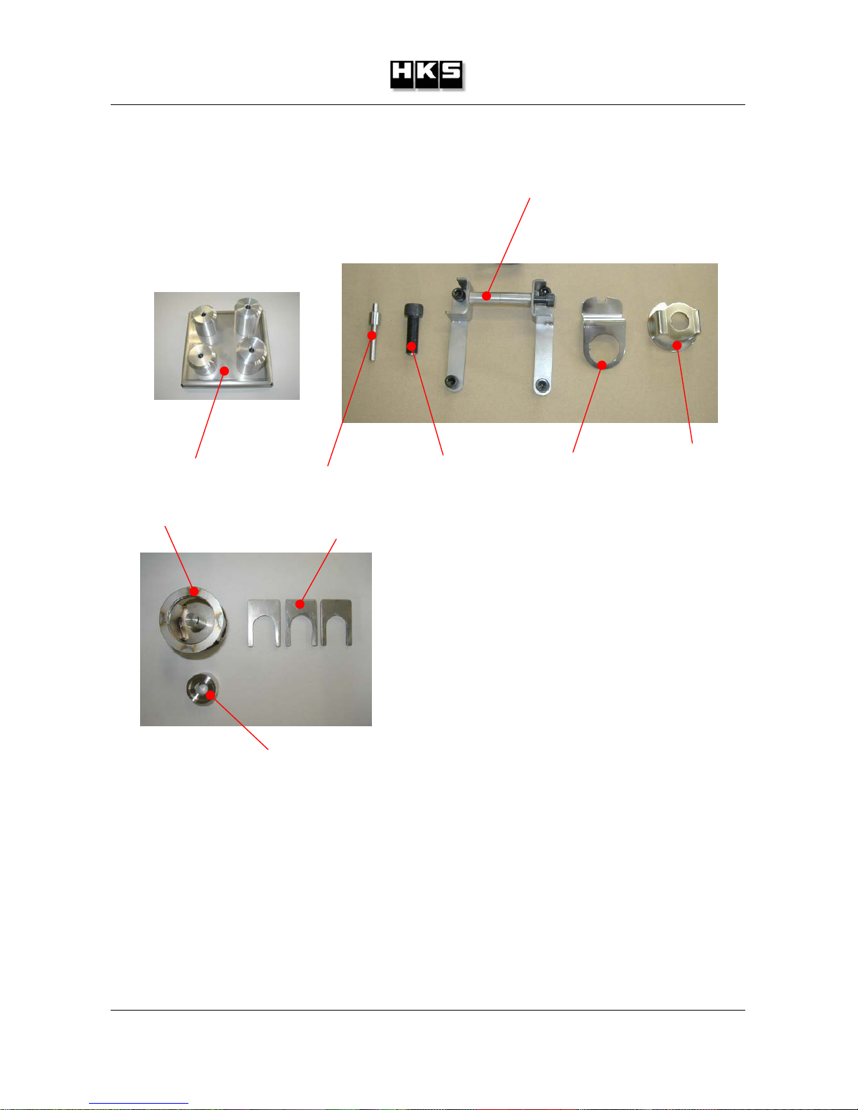
2.1 Special tools
In addition to this service manual, please refer to the following.
(1) HKS 700E Installation instruction Manual
(2) HKS 700E Operations Manual
(3) HKS 700E Parts List
ST-01 ST-02 ST-03 ST-05 ST-06
ST-04
ST-07 ST-08
ST-09

Service Manual
Effectivity: HKS700E after S/N 100600 - 7 -
3 Disassembly
3.1 Carburetors removal
NOTE: Identify both carburetors to RH/LH cylinders.
3.1.1 Upper type
• Remove 2 nuts ①M6.
3.1.2 Horizon type
• Remove tension spring.
• Loosen clamp screw ①and remove carburetor
by turning action.
3.2 Intake manifolds removal
• Remove 2 bolts ①M8 and intake manifold.
• Remove intake gasket ②.
②
①
①
①

Service Manual
Effectivity: HKS700E after S/N 100600 - 8 -
3.3 Electric starter removal
• Remove 2 bolts ①M6.
• Shift to remove electric
starter.
3.4 Spark plug removal
• Remove 4 spark plugs.
①
Service Manual
Effectivity: HKS700E after S/N 100600 - 9 -
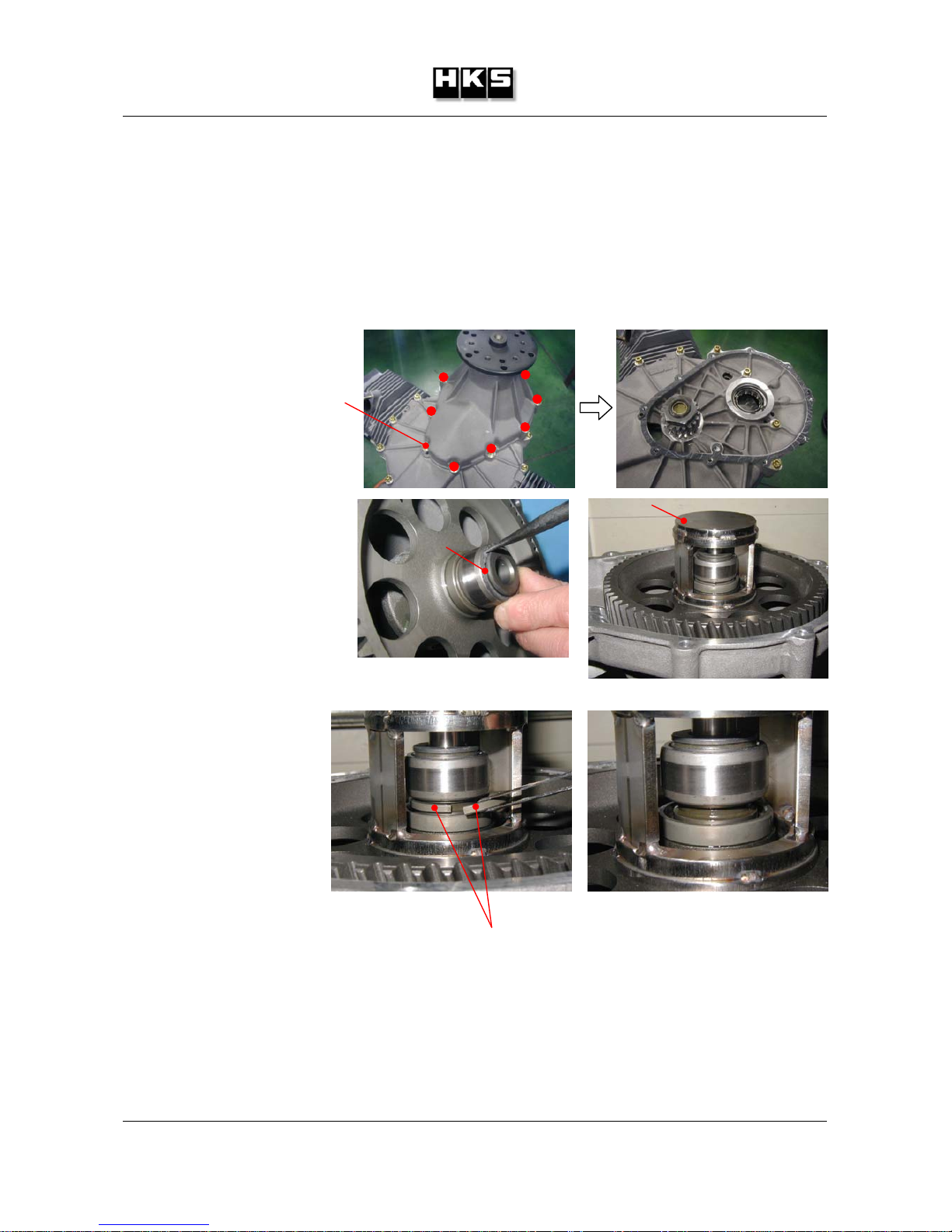
3.5 Gearbox removal and disassembly
3.5.1 Atype (ratio2.58)
• Remove 8 bolts ①M6.
3.5.2 B type (ratio3.47)
• Remove 10 bolts ①M6.
• Shift to remove gearbox.
• Remove circlip ①.
• Set ST-07 as shown.
• Compress gear and
remove half rings ①.
S
T
-07
①
①
①
Other manuals for 700E
1
Table of contents
Other HKS Engine manuals


