HM Electronics IC100 Technical specifications

HME# 400190
Rev E 11/7/02
IC100/200
Cabled Drive-Thru
Intercom Systems
and
IC200RIC200R
Remote Station
Installation / Operation / Maintenance Instructions

Table of Contents
SECTION 1. SYSTEM DESCRIPTION
1.1 GENERAL DESCRIPTION ........................................................ 1
1.2 MAIN COMPONENTS ........................................................... 1
1.3 OPTIONAL EQUIPMENT ......................................................... 1
1.4 CONTROLS, SWITCHES AND CONNECTORS ........................................ 2
1.4.1 FRONT PANEL ................................................................ 2
1.4.2 RIGHT SIDE .................................................................. 3
1.4.3 LEFT SIDE ................................................................... 3
SECTION 2. SYSTEM OPERATION
2.1 IC100 INTERCOM OPERATION (SINGLE-CHANNEL) ................................. 4
2.2 IC200 INTERCOM OPERATION (DUAL-CHANNEL) ................................... 5
2.3 IN CASE OF PROBLEMS ........................................................ 6
SECTION 3. SYSTEM INSTALLATION
3.1 PREPARATION FOR INSTALLATION ............................................... 7
3.1.1 DETERMINING THE BEST LOCATION FOR THE IC100/IC200 BASE STATION ............... 7
3.1.2 UNPACKING THE SYSTEM ...................................................... 7
3.1.3 TOOLS REQUIRED ............................................................. 7
3.2 INSTALLATION CHECKLIST ...................................................... 8
3.3 IC100 / IC200 INSTALLATION AS STAND-ALONE INTERCOM ........................... 9
3.3.1 CABLE PULLING AND PREPARATION .............................................. 9
3.3.2 OUTSIDE SPEAKER INSTALLATION .............................................. 10
3.3.3 VEHICLE DETECTON .......................................................... 10
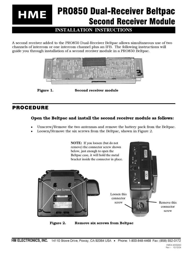
3.3.4 OPTIONAL VDB100/101 VEHICLE DETECTOR BOARD INSTALLATION ................... 11
3.3.5 MOUNTING THE BASE STATION ................................................. 12
3.3.6 INSIDE CABLE CONNECTIONS .................................................. 13
3.3.7 INSTALLING THE OPTIONAL IC200R REMOTE STATION .............................. 15
3.3.8 ADJUSTING THE IC100/IC200 BASE STATION ...................................... 15
3.3.9 ADJUSTING THE OPTIONAL IC200R REMOTE STATION .............................. 16
3.4 IC100/IC200 INSTALLATION AS WIRED BACKUP INTERCOM WITH SYSTEM 2500D ......... 18
3.4.1 IC100/IC200 INSTALLATION WITH ASW2 IN AUDIO SYSTEM BASE STATION ............. 18
APPENDIX A: IC100/IC200 INTERFACE DESCRIPTION .................................... 22
APPENDIX B: THEORY OF OPERATION AND BLOCK DIAGRAMS ........................... 24
APPENDIX C: ASW2 AUDIO SWITCHER CONNECTIONS .................................. 30
APPENDIX D: IC100/IC200 LIST OF SPECIFICATIONS .................................... 31
The HME logo and the word COMMUNICATOR are registered trademarks of HM Electronics, Inc.
®
© Copyright HM Electronics, Inc. — November 2002

List of Figures
Figure Page Title
11 IC200 base station
22 IC200 control panel
33 IC100/IC200 base station side views
44 IC100 control panel
55 IC200 control panel
69 Cable route
710 Cable connections
811 Installing the optional VDB100/101
912 Base station on wall
10 12 Base station on pedestal
11 13 Mounting bracket can be mounted in either position on base station
12 14 Stand-alone IC100/IC200 Intercom and optional
IC200R Remote Stationwiring diagram
13 15 Volume adjustments
14 16 S2 switch OUTBOUND settings
15 17 IC100/IC200 Intercom optional accessories wiring diagram
16 18 WBS2500D Base Station, inside view
(with VDB100/101 in both the WBS2500D Base Station
and the IC100/IC200 Base Station)
17 19 IC100/IC200 connections with WBS2500D Base Station, rear views
(with VDB100/101 in both units)
18 20 WBS2500D Base Station, inside view
(with VDB100/101 in WBS2500D Base Station only)
19 21 IC100/IC200 connections with WBS2500D Base Station, rear views
(with VDB100/101 in WBS2500D Base Station only)

1
SECTION 1. SYSTEM DESCRIPTION
Figure 1. IC200 base station
1.1 GENERAL DESCRIPTION
The IC100 and IC200 are cabled drive-thru
audio systems primarily for use in quick-
service restaurants. The differences between
the two systems are described below. All units
have digital touch controls for easy operation.
IC100 - The IC100 is a single-channel intercom
system for communication between the
order taker and drive-thru customer.
It has a stand-alone base station
IC200 - The IC200 is a dual-channel intercom system. It has a base station that is used
alone for single-channel communication between the order taker and drive-thru
customer. With the addition of a remote station, it can be used for dual-channel
communication. Channel A is used for communication between the order taker
and drive-thru customer, while Channel B is used for communication between the
order taker and other employees within hearing range of the remote station.
1.2 MAIN COMPONENTS
Component Part Number
One of the following:
IC100 Base Station K14498
or IC100 Base Station with VDB K14724
or IC200 Base Station K14476
or IC200 Base Station with VDB K14735
One of the following:
AC adapter 115V/16.5VAC output 760103
AC power cable 115150
or AC adapter 230V/16.5VAC output 760106
SP2000A Speaker K10360
200ft. speaker cable 855001
1.3 OPTIONAL EQUIPMENT
Equipment Part Number
For IC100, IC200 or IC200R:
Footswitch with cable K01674
Pedestal, 15-27 inches (.38-.69 meters) K15343
For either IC100 or IC200:
Ceiling speaker K01203
SP3000 Speaker K00550
Handset speaker/microphone with push-to-talk button K15310
or Gooseneck microphone with push-to-talk button 407073
For IC200 only:
IC200R Remote Station K14454
Remote station interface cable K15321

2
Figure 2. IC200 control panel
1.4 CONTROLS, SWITCHES AND CONNECTORS
1.4.1 FRONT PANEL:
The front panel on the IC100 and IC200 base stations and the IC200R Remote Station are
identical, except the IC200 and IC200R have channel B buttons with TALK and LISTEN lights.
The front panel controls are as follows.
POWER light comes on when the unit is plugged in, and the OFF ON switch is in the ON
position. It remains on as long as the unit is receiving power.
VEHICLE light comes on when a vehicle approaches the outside speaker. The light is
accompanied by a vehicle-present signal (beeping). The light remains on as long as the
vehicle is present, but the beeping stops as soon as the channel A button is pressed.
For systems with a pulse-detection vehicle detector such as an air hose, the vehicle light
will go off when the STANDBY button is pressed.
STANDBY light comes on when the unit is turned on. The STANDBY light remains on
whenever the intercom is in the standby mode.
TALK light comes on when the A or B button is pressed.
LISTEN light comes on when the A or B button is released.
STANDBY button is used to put a customer on hold. To resume speaking to the
customer, press and hold the channel A button. The STANDBY button is also used to
return to the standby mode if you are talking to a crew member on channel B.
NOTE: With some types of vehicle detectors, it may be necessary to press the STANDBY
button each time you finish speaking to a customer.
Channel A button is used to speak to the customer at the outside speaker. Press and
hold button A while speaking, and release it to listen.
Channel B button is used only to speak to other crew members through the IC200R remote
station. Whoever initiates the communication must press and hold button B while speaking,
and release it to listen. The person at the other unit can speak and listen hands-free.
Volume buttons are used to raise or lower the inbound volume (the customer's voice that
you hear through the base station speaker). Press and hold the up arrow to increase the
volume, or the down arrow to decrease the volume.

3
Right side Left side
1.4.2 RIGHT SIDE:
OFF ON switch located under the right side of the base station, is used to turn
the intercom on or off.
1.4.3 LEFT SIDE:
DAY NIGHT switch located under the left side of the base station, is used to
lower the outbound speaker volume in the NIGHT position, and to raise the
outbound speaker volume in the DAY position.
HANDSET connector on the left side of the base station, is used to connect an
optional handset to the intercom. When using a handset, the button on the
handset is used instead of button A, and the customer is heard through the
handset earpiece instead of through the speaker on the base station. Also, when
the handset is connected to the unit, the customer will be heard in the handset
only. The vehicle tone, however, will be heard through the speaker in the base
station.
Figure 3. IC100 / IC200 base station side views

4
SECTION 2. SYSTEM OPERATION
Figure 4. IC100 control panel
2.1 IC100 INTERCOM OPERATION
(SINGLE-CHANNEL)(SINGLE-CHANNEL)
The ACTION column below tells you how
to operate your IC100, step-by-step.
The RESULT column to the right tells you
what you should see or hear after each
action.
ACTION RESULT
11 Plug AC adapter into electrical outlet. POWER and STANDBY lights come on.
Place OFF ON switch in ON position.
2Vehicle arrives at menu board or speaker post. Beep - - - - Beep - - - - Beep - - - -
Beep
VEHICLE light comes on. STANDBY light goes
off. Intermittent beeps will be heard until the
?A” button is pushed.
NOTE: If your IC100 has a gooseneck microphone or telephone handset, when steps 3 - 5 below
refer to the ?A” button, press/hold/release the button on the microphone or handset instead. If you
are using a handset, the vehicle arrival tone will still be heard from the base station.
3Press and hold the ?A” button. TALK light ?A” comes on.
4Continue holding the ?A” button. Remain arm's length The customer should hear your voice.
from the base station and speak to the customer.
5Release the ?A” button. LISTEN light ?A” comes on. TALK light goes
Listen to the customer. off.
6While the customer is speaking, press the The customer's voice should become louder
VOLUME up arrow to make his/her voice louder, or or softer.
press the down arrow to make the voice softer.
NOTE: You can press and hold the arrow, or
press it repeatedly. Do not lower volume all the
way, or you will not hear the vehicle arrival tone.
Holding down either arrow, it will take
approximately 4 seconds to adjust the volume
from highest to lowest, or vice versa.
7If you would like to put the customer on hold, press STANDBY light comes on. Neither you nor the
the STANDBY button. customer can hear each other. NOTE: If you
are using a pulse detection vehicle detector,
such as an air hose, the vehicle light will go off
when the STANDBY button is pressed.
8Vehicle leaves drive-thru area. STANDBY light comes on. VEHICLE light goes
off. IC100 remains in standby until arrival of next
vehicle. NOTE: If your system does not
automatically revert to STANDBY, you may have
to press the STANDBY button when you have
finished talking to a customer.

5
Figure 5. IC200 control panel
2.2 IC200 INTERCOM OPERATION
(DUAL-CHANNEL)(DUAL-CHANNEL)
The ACTION column below tells you how
to operate your IC200, step-by-step.
The RESULT column to the right tells you
what you should see or hear after each
action.
ACTION RESULT
11 Plug AC adapter into electrical outlet. POWER and STANDBY lights come on.
Place OFF ON switch in ON position.
2Vehicle arrives at menu board or speaker post. Beep - - - - Beep - - - - Beep - - - -
Beep
VEHICLE light comes on. STANDBY light goes
off. Intermittent beeps will be heard until the
?A” button is pushed.
NOTE: If your IC200 has a gooseneck microphone or telephone handset, when steps 3 - 5 below
refer to the ?A” button, press/hold/release the button on the microphone or handset instead. If you are
using a handset, the vehicle arrival tone will still be heard from the base station.
3Press and hold the ?A” button. TALK light ?A” comes on.
4Continue holding the ?A” button. Remain arm's length The customer should hear your voice.
from the base station and speak to the customer.
5Release the ?A” button. LISTEN light ?A” comes on. TALK light goes
Listen to the customer. off.
6While the customer is speaking, press the The customer's voice should become louder
VOLUME up arrow to make his/her voice louder, or or softer.
press the down arrow to make the voice softer.
NOTE: You can press and hold the arrow, or
press it repeatedly. Do not lower volume all the
way, or you will not hear the vehicle arrival tone.
Holding down either arrow, it will take
approximately 4 seconds to adjust the volume
from highest to lowest, or vice versa.
7If you would like to put the customer on hold, press STANDBY light comes on. Neither you nor the
the STANDBY button. customer can hear each other. NOTE: If you
are using a pulse detection vehicle detector,
such as an air hose, the vehicle light will go off
when the STANDBY button is pressed.
8Vehicle leaves drive-thru area. STANDBY light comes on. VEHICLE light goes
off. NOTE: If you push the ?B” button after a
customer arrives, and the customer pulls away,
the system will not revert to standby. You must
push the STANDBY button.

6
Channel ?B” Operation
(for talking to other crew members)
9Press and hold the ?B” button. TALK light ?B” comes on.
10 Continue holding the ?B” button. Remain arm'sCrew members should hear your voice from
length from the base station and speak to crewspeaker in remote station.
members .
11 Release the ?B” button. Listen to crew member's Your unit: TALK light ?B” goes off.
response. Crew member does not have to press LISTEN light ?B” comes on.
the "B" button to talk. Crew unit: LISTEN light ?B” goes off.
TALK light ?B” comes on.
12 While the crew member is speaking, you can The crew member's voice should become
press the VOLUME up arrow to make his/her voice louder or softer.
louder, or press the down arrow to make the voice
softer. NOTE: You can press and hold the arrow,
or press it repeatedly. Do not lower volume all the
way, or you will not hear the vehicle arrival tone.
Holding down either arrow, it will take
approximately 4 seconds to adjust the volume
from highest to lowest, or vice versa.
2.3 IN CASE OF PROBLEMS
PROBLEM SOLUTION
1Unit not on; power light not on Be certain AC adapter is plugged into
electrical outlet, and OFF ON switch is in ON
position.
2No inbound audio; vehicle tone not heard Push volume up arrow to increase volume.
3Vehicle tone not heard; inbound audio OK Call HME service representative.
4No outbound or inbound volume Call HME service representative.
5Inbound volume low; outbound volume OK Call HME service representative.
6Outbound volume low; inbound volume OK Be certain DAY NIGHT switch is in DAY
position.
7No ceiling speaker audio heard Call HME service representative.
8Feedback in ceiling speaker when talking to Call HME service representative.
customer
9Remote station does not respond to A-TALK Call HME service representative.
button on base station
10 Remote station does not respond to vehicle tone Call HME service representative.
NOTE: To talk to your HME service representative, call 1-800-848-4468
or Fax 858-552-0172 (Attn: Technical Support)

7
SECTION 3. SYSTEM INSTALLATION
3.1 PREPARATION FOR INSTALLATION
Before installing the IC100/IC200/IC200R, coordinate the time of installation with the store
owner/manager, to minimize disruption of business. Approximate time required for
installation is:
!for stand-alone intercom system at new store — 3½ hours
!with existing wireless audio system, where no wired intercom was previously
installed — 1½ hours
!as replacement for previously installed wired intercom — 2 hours
Be certain the site has been properly prepared according to the following guidelines.
!Electrical power must be connected and available.
!Some type of compatible vehicle detector system must already have been installed
in the drive-thru lane. The system can sense positive or negative changes,
0V to +20VDC, pulse or continuous presence.
!If the IC100/IC200 will be used as a stand-alone drive-thru intercom system, 1½ inch
(40 mm) conduit must already be installed for routing cable from the speaker post or
menu board into the building.
NOTE: If the IC100/IC200/IC200R will be installed with an existing wireless drive-
thru audio system, pulling new cables from the outside speaker and vehicle detector
to the building may not be required. Instead, IC100/200 cables can be connected to
the wireless audio system base station.
3.1.1 DETERMINING THE BEST LOCATION FOR THE IC100/IC200 BASE STATION
Discuss the preferred location of the IC100/IC200 base station with the customer,
depending on its intended use and the following considerations.
!The IC100/IC200 base station must be mounted where cables can easily be routed
from outside to the unit and/or from the unit to the wireless audio system base station.
!An AC electrical outlet must be close enough for the AC adapter cord to reach from
the outlet to the IC100/IC200 base station, or the cord will need to be extended.
3.1.2 UNPACKING THE SYSTEM
Check the packing list for each IC100/IC200/IC200R item as it is unpacked to verify
receipt of all standard components and optional equipment listed.
3.1.3 TOOLS REQUIRED
For all installations: Additional requirements for
Phillips (cross-point) screwdriver, size #2
standard (slotted) screwdriver, 1/8 inch (4 mm)
power drill and drill-bit set
fish tape, 100 feet (30 meter)
wire cutter / stripper
stand-alone system installations:
soldering iron
rosin-core solder
electrical tape

8
3.2 INSTALLATION CHECKLIST
The following checklist is provided as a brief guideline for the steps required in each of
the possible installation scenarios. Detailed installation instructions for stand-alone
installation and installation with the HME System 2500D are on the following pages.
IC100 / IC200 as stand-alone wired intercom
New installations Retrofit installations
€Install outside speaker. €Disconnect and mark cables from old unit.
€Install vehicle detector, if not already installed. €Remove old unit.
€Pull cables from outside speaker into building. €Install pedestal and/or base station
€Install pedestal and/or base station mounting bracket.
€If necessary, drill hole in mounting surface for cable
to reach base station, and pull cables through hole in
pedestal and/or mounting bracket. €Connect cable wires to connector plugs,
€Connect cable wires to connector plugs, and plug
into base station. Refer to Figure 11 for connections.
€Make required adjustments.
mounting bracket.
€Route cable through hole in pedestal and/or
mounting bracket.
and plug into base station. Refer to Figure 11
for connections.
€Make required adjustments.
IC100 / IC200 Intercom as wired backup for HME wireless audio system
New installations Retrofit installations Retrofit installations
replacing old wired system with no old wired system
€Install audio system first. €Disconnect and mark cables from €Install pedestal and/or base
€Install pedestal and/or base
station mounting bracket. €Route cable from audio
€If necessary, drill hole in
mounting surface for cable to
reach base station, and pull
cables through hole in pedestal
and/or mounting bracket.
€Connect cable wires from
audio system to IC100/IC200
connector plugs, and plug into
base station. Refer to Figure 16
or 17 for connections.
€Make required adjustments.
old unit.
€Remove old unit.
€Install pedestal and/or base station
mounting bracket.
€Route cable through hole in
pedestal and/or mounting bracket.
€Connect cable wires from audio
system to IC100/IC200 connector
plugs, and plug into base station.
Refer to Figure 16 or 17 for connections.
€Make required adjustments.
station mounting bracket.
system base station to
IC100/IC200 base station
location, and through hole in
pedestal and/or mounting
bracket.
€Connect cable wires from
ASW1/ASW2 connectors in audio
system to IC100/IC200 connector
plugs, and plug into base station.
Refer to Figure 16 or 17 for
connections.
€Make required adjustment.
IC200R Remote Station
€Install remote station pedestal and/or mounting bracket, and drill hole for cable to come through
bracket to remote station.
€Pull cable from remote station to base station location, and through hole into pedestal and/or
mounting bracket.
€Connect cables to connector plugs, and plug them into unit. Refer to Figure 12 for remote station
connections.
€Make required adjustments.

9
Figure 6. Cable route
3.3 IC100 / IC200 INSTALLATION AS STAND-ALONE INTERCOM
3.3.1 CABLE PULLING AND PREPARATION
CAUTION: If not using the HME Audio Cable, be certain the speaker wires are a
twisted pair.
The enclosed HME cable contains four color-coded, insulated wires and a bare shield
(drain) wire. This cable will connect the outside speaker and vehicle detector loop to the
IC100/IC200 base station.
Pull the cable through the underground conduit from the speaker post or menu board
area into the building as follows.
!Run fish tape from the drive-thru customer service area, inside the building, through
the conduit to the speaker post or menu board.
!Go outside and fasten the cable to the fish tape where it comes out of the conduit,
and return to the customer-service area in the building.
!Pull the fish tape and cable through the conduit, into the customer-service area. As the
cable comes through the conduit, disconnect it from the fish tape and continue pulling
enough of the cable through the conduit to reach the the base station.
!Route the cable to the base station.
!Return to the speaker post or menu board, and route the cable from the outside
conduit to the inside of the speaker post or menu board.
!Cut the cable, leaving approximately one foot of slack.
!Remove approximately 2 inches (50 mm) of the outer insulation from the end of the
cable. Strip approximately ½ inch (12 mm) of insulation from each of the four wires in
the cable.

10
Figure 7. Cable connections
3.3.2 OUTSIDE SPEAKER INSTALLATION
!Mount the outside speaker behind the speaker grill in the speaker post or menu
board with the mounting hardware provided.
!Splice the black and white wires coming from the back of the speaker to the green
and white wires of the cable in the speaker post or menu board (Figure 7).
!Solder the connections and wrap them with electrical tape.
!Tape the shield wire out of the way.
!If an external, non-loop type vehicle detector is going to be used, clip the red and
black cable wires off, close to the outer cable insulation.
3.3.3 VEHICLE DETECTION
Using a Vehicle Detector Loop:
!Run the vehicle detector loop cable/wires to the speaker in the speaker post or menu
board.
!Splice the wires from the vehicle detector loop to the red and black wires of the same
cable that is connected to the speaker (Figure 7).
!Solder the connections and wrap them with electrical tape.
External, Non-Loop Type Vehicle Detector (optional):
With any type of external, non-loop type vehicle detector, route the detector cable directly into
the building to the area where the IC100/IC200 base station will be mounted.

11
Figure 8. Installing the optional VDB100/101
3.3.4 OPTIONAL VDB100/101 VEHICLE DETECTOR BOARD INSTALLATION
If you are installing an HME VDB100/101 into the IC100/IC200, refer to Figure 8 and follow
the instructions below.
!Using the tip of a small, standard (slotted) screwdriver, remove the plastic screw
cover from each of the four corners on the bottom of the IC100/IC200 base station.
Using a Phillips (cross-point) screwdriver, remove the screw from under each of the
screw covers.
!VERY CAREFULLY, lift the cover off the base station.
CAUTION: Do not pull the cables inside the base station loose
when lifting the cover.
!Carefully position the three holes in the VDB100/101 circuit board over the three
plastic standoffs on the large circuit board inside the IC100/IC200 base station.
Press down on the VDB100/101 until the tips of the three standoffs snap through the
holes.
!Connect the two loose wires from the large circuit board, labled ?VDB TB1,” to the
TB1 connector on the VDB100/101.
!Connect the cable attached to the P1 connector on the VDB100/101 to the J6
connector on the large circuit board, near the end of the VDB100/101.
!Replace the cover on the IC100/IC200 base station by carefully fitting it over the end
panels, so the panels fit into the grooves inside the ends of the cover. Slide the
cover down until it fits evenly against the bottom of the unit. Using a Phillips (cross-
point) screwdriver, lightly tighten the screws at the four corners of the cover.
Replace the plastic screw covers over each of the four screws.

12
Figure 9. Base station on wall
Figure 10. Base station on pedestal
3.3.5 MOUNTING THE BASE STATION
The base station can be mounted on the wall or on a counter top. In either case, the unit
and its mounting bracket can be mounted directly on the wall or counter top (Figure 9), or
they can be extended from the wall or counter surface by mounting them on the optional
mounting pedestal (Figure 10). The base station can be mounted in either direction on
its mounting bracket (as shown in Figure 9). To mount the base station, follow the
instructions below.
!If you want to route the cable through the wall or counter top to the base station, drill
a hole in the mounting surface where the unit will be mounted. The hole must be
large enough for the cable to come through. Hold the mounting bracket or pedestal
flat against the surface, with its large, center hole over the hole drilled in the counter
or wall, and continue with the next step.
To mount the base station and mounting bracket directly on a wall or counter surface:
!Hold the mounting bracket flat against
its mounting surface, and use a pencil
to mark the surface through the four
drill holes on the back of the bracket.
!Drill the four holes with a 3/16" (8mm)
drill bit.
!Fasten the bracket to the surface using the
enclosed screw anchors and screws.
To mount the base station and mounting bracket using the optional pedestal:
!Hold the base of the pedestal flat against its
mounting surface, and use a pencil to mark
the surface through the four drill holes on the
base of the pedestal.
NOTE: The positions of the pedestal and
mounting bracket can be varied to achieve
the most desirable angle for mounting the
base station.
!Fasten the pedestal to the surface using the
enclosed lag screws or bolts and nuts.
!Fasten the mounting bracket to the top of the
pedestal with the four screws supplied with
the base station.
!Adjust the height of the base station by
loosening the two screws on the side of the
pedestal, raising or lowering the pedestal to
the desired level, and retightening the
screws.

13
Figure 11. Mounting bracket can be mounted
in either position on base station
3.3.6 INSIDE CABLE CONNECTIONS
!Run the cable(s) to the base station. It can be routed either through the hole in the
back of the mounting bracket, or through the hole in the mounting surface into the
mounting bracket, or through the pedestal and into the mounting bracket.
!If an external loop detector is used, connect the red and black wires to the external
detector's loop input. Route a cable from the output of the external detector to
connector P11, pins 4 and 5 on the base station, as shown in Figure 12.
!Remove 4 inches (100 mm) of outer insulation from the end of the cable(s) near the
IC100/IC200 base station, and strip approximately ¼ inch (6 mm) of insulation from
each of the four cable wires coming from the outside speaker and vehicle detector.
!Connect the color-coded wires to the P11, 18-pin IC100/IC200 connector plug
according to the wiring diagram in Figures 12, 17 and 19.
!Connect the 16VAC electrical adapter to the P11 connector plug according to
Figures 12, 17 and 19. Fully insert wires into connector plug to prevent shorting the
16VAC adapter.
!Plug the P11 connector plug into the J11 base station connector as shown in Figures 12,
17 and 19.
!Mount the base station on the mounting bracket by placing the two "L" flanges on the
bracket through two of the slots on the back of the unit (Figure 11), and guiding the
other end of the base station downward onto the two catches on the mounting
bracket. Press the two buttons near the catches on the bracket to align the catches
with the two slots on the back of the base station while pressing the unit down on the
catches until they lock in place.

14
Figure 12. Stand-alone IC100 / IC200 Intercom and
optional IC200R Remote Station wiring diagram

15
Figure 13.
Volume adjustments
3.3.7 INSTALLING THE OPTIONAL IC200R REMOTE STATION
!Mount the remote station in the same manner as the base station in paragraph 3.3.5.
To minimize feedback, the base station and remote station should be isolated as
much as possible from each other.
!Starting at the remote station, route the unconnected end of the remote station
interface cable through or along the wall to the location of the IC100/IC200 base
station.
!Cut the interface cable and connect it to the supplied P2 connector plug as shown in
Figure 12.
!Plug the P2 connector plugs into the J2 connectors on the base station and the
remote station. On the base station, the S2 switch labeled NO REMOTE must be in
the OFF position.
!Mount the remote station on the wall or counter top as described in paragraphs 3.3.5
and 3.3.6, and shown in Figures 9 and 11.
3.3.8 ADJUSTING THE IC100/IC200 BASE STATION
S2 Switch settings: 8Not Used
7OFF -+ VEH POL
The factory switch settings are 6OFF -A LISTEN CEIL MUTE
shown to the right. 5ON -A TALK CEIL MUTE
4ON -NO REMOTE
Additional explanation of the switch 3OFF -PULSE DET
settings is found in Appendix A. 2ON -ATTEN 2 OUTBOUND
1ON -ATTEN 1 OUTBOUND
Volume adjustments: (Refer to Figures 13 and 14.)
Volume adjustments (VOLUME ADJ) for the vehicle tone level
(VEH TONE), the ceiling speaker level (CEILING) and the
outbound/inbound volume level (MASTER) are located on the
rear panel of the IC100/IC200 base station.
NOTE: The MASTER VOLUME ADJ on the rear panel
controls inbound and outbound audio and vehicle tone
levels. Always adjust the MASTER VOLUME ADJ first for
optimum outbound audio.
!The VOLUME adjustments for inbound volume level are
located on the front panel keypad of the IC100/IC200.
!Adjust the MASTER VOLUME ADJ for the desired outbound volume level.
If the maximum level is not high enough, it can be increased by setting the S2
OUTBOUND ATTEN 1 and ATTEN 2 switches as shown in Figure 14. Both switches
in the ON position will provide the best audio levels in most installations.
!If the inbound volume is too high at full volume, configure the S2 OUTBOUND
ATTEN 1 or ATTEN2 switches as shown in Figure 14 to raise the outbound level.
Then readjust the master VOLUME ADJ for the desired outbound volume.
This will balance the inbound and outbound audio levels.

16
Figure 14. S2 switch OUTBOUND settings
!Adjust the INBOUND VOLUME by pushing the arrows on the front panel.
!Adjust the VEH TONE VOLUME ADJ to the desired level when a vehicle is present.
Do not adjust the volume too low on the front panel, or the VEH TONE may not be
heard.
!Adjust the CEILING VOLUME ADJ on the rear panel of the IC100/IC200 base station
for the desired ceiling speaker volume level.
NOTE: Feedback may occur at high volume setting if the distance between the
base station and the ceiling speaker is too short, and the A TALK CEIL MUTE S2
switch is in the OFF position. If feedback does occur, either relocate the ceiling
speaker or lower the volume with the CEILING VOLUME ADJ control on the rear
panel of the IC100/IC200 base station.
3.3.9 ADJUSTING THE OPTIONAL IC200R REMOTE STATION
S2 Switch settings:
The factory switch settings are as follows.
1Hear outbound – OFF
2Vehicle present tone – ON
3A channel – ON
Additional explanation of the switch settings is found in Appendix A.
Volume adjustments:
!Adjust the inbound volume to the desired level by pushing the arrows on the front
panel.
!The outbound volume is not adjustable.

17
Figure 15. IC100 / IC200 Intercom optional accessories wiring diagram
This manual suits for next models
1
Table of contents
Other HM Electronics Intercom System manuals
