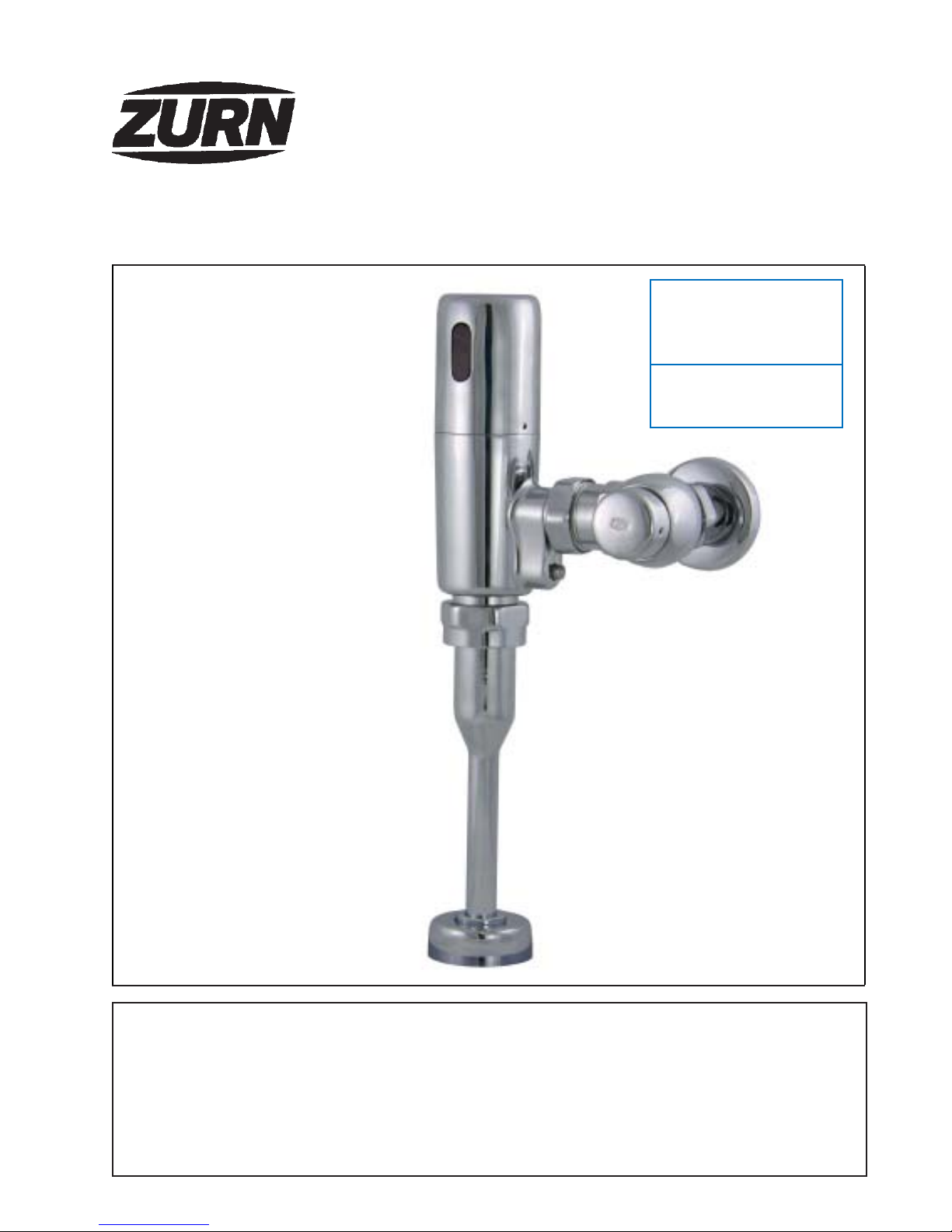
ZURN ZEG6003EV User manual

®
AquaSense®EVTM
ZEG Series
Automatic Sensor-Operated,
Battery-Powered Flushometer
Installation, Operation, Maintenance,
and Parts Manual
Patented and Patents Pending
LIMITED WARRANTY
All goods sold hereunder are warranted to be free from defects in material and factory workmanship for a period of three years from the date of
purchase. Decorative finishes warranted for one year. We will replace at no costs goods that prove defective provided we are notified in writing of
such defect and the goods are returned to us prepaid at Sanford, NC, with evidence that they have been properly maintained and used in
accordance with instructions. We shall not be responsible for any labor charges or any loss, injury or damages whatsoever, including incidental or
consequential damages. The sole and exclusive remedy shall be limited to the replacement of the defective goods. Before installation and use, the
purchasershalldeterminethesuitabilityoftheproductforhisintendeduseandthepurchaserassumesallriskandliabilitywhateverinconnectiontherewith.
Wherepermittedbylaw,theimpliedwarrantyofmerchantabilityisexpresslyexcluded.Iftheproductssoldhereunderare“consumerproducts,”the
impliedwarrantyofmerchantabilityislimitedtoaperiodofthreeyearsandshallbelimitedsolelytothereplacementofthedefectivegoods.Allweights
statedinourcatalogsandlistsareapproximateandarenotguaranteed.
ZEG6003EV Flushometer for
Z5798 Low Flow Urinal
Sensor-Operated, Battery-Powered
Urinal System
DOCKETED
California Energy Commission
AUG12 2014
TN 73587
14-AAER-01

FV454 Rev C 1/28/13
Page 2
PRIOR TO INSTALLATION
Prior to installing the ZEG EcoVantage urinal flushometer
valve, install the items listed below:
• Urinal fixture
• Drain line
• Water supply line
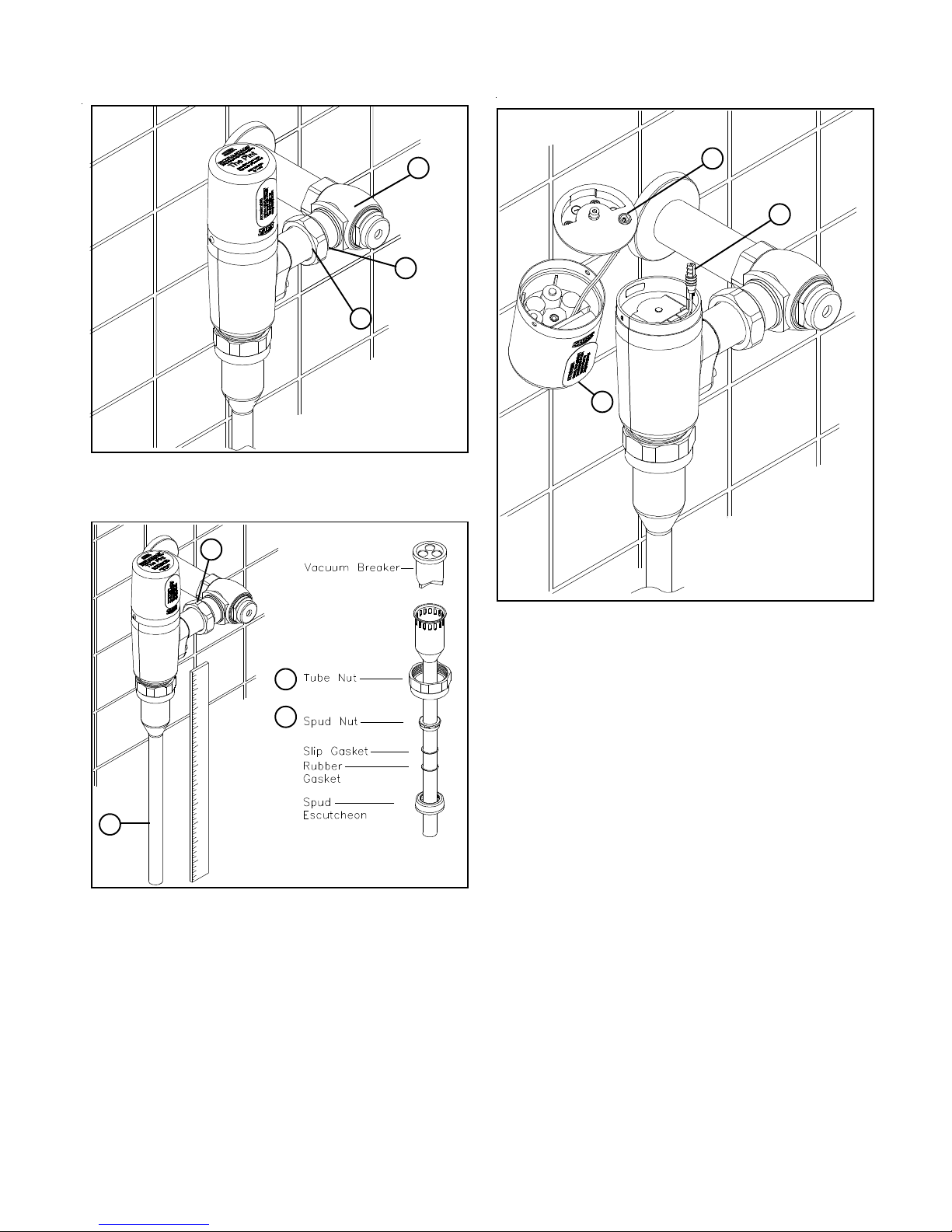
1.) Install stop valve assembly (A) using proper size supply
escutcheon and sweat solder adapter kit if applicable.
Note: Thread sealing compounds should be avoided.
Recommend teflon tape to seal NPT only.
3.) Prior to inserting the flush valve tailpiece (B) into stop valve
(A), be certain that the O-ring seal (C) is located in O-ring
seal groove at the end of the tailpiece and that the locking
nut (D) and locking snap ring (E) are located as shown.
Care should be taken not to damage the O-ring when
inserting the tailpiece into the stop valve. If lubrication is
needed, wetting the O-ring with water will be sufficient.
1
3
E
C
A
D
B
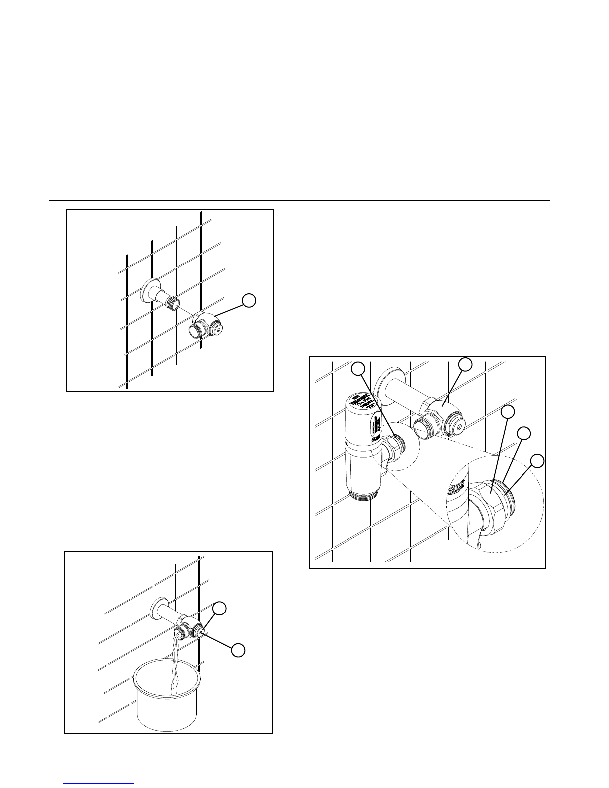
Before the supply water is turned on, be sure all stop valves
are closed off tight. The stop valves can be opened and closed
by using the adjusting screw (S) located at the center of the
stop valve cap (T). Stop valve adjustments can only be made
by using the adjusting screw (S). It is not necessary to re-
move the stop valve cap (T) when making adjustments. If
for any reason it becomes necessary to remove the stop
valve cap (T), be certain the water is shut off at the main
supplyvalve.
T
2
2.) When all stops are connected to the water supply and
water pressure is available, it is recommended that the
supply piping be flushed to remove dirt, metal chips, etc.,
from system.
A. Before the valve is installed, open each stop fully for a brief
time and catch the water in a two gallon or larger bucket.
For multiple installations, start with the stop valve closest
tothe watersupply andwork towardthe mostremote valve.
B. Due to the small passages and orifices, it is not possible
to flush the piping through the low volume valve.
C. Once the lines are flushed, the valve can be installed.
S
A
2
IMPORTANT:
•All Plumbing is to be installed in accordance with applicable
codes and regulations.
• Water supply lines must be sized to provide an adequate
volume of water for each fixture.
• Flush all water lines prior to operation (See Step 2).
• Dirt and debris can cause flush valve to run continuously.
• Sensor units should not be located across from each other
or in close proximity to highly reflective surfaces.
• DO NOT use pipe dope or plumbers grease on any part or
connection of this valve. These materials can block small
orifices in the flush valve and cause malfunctions.
The ZEG is designed to operate with 20 to 120 psi (138 to
827 kPa) of water pressure, however the required water pres-
sure is determined by the fixture. Contact the fixture manu-
facturer for the proper static and flow operating pressures.
Protect the chrome or special finish of this flushometer. Do
not use toothed tools to install or service the valve.

FV454 Rev C 1/28/13
Page 3
7
4.) Insert the flush valve tailpiece (B) into the stop valve (A)
and hand tighten the lock nut (D) to the stop valve. Plumb
the entire unit.
5.) Determine the length of vacuum breaker tube (F)
required to join the flush valve and fixture spud. Cut the
vacuum breaker tube, if required, to this length. Assemble
the vacuum breaker tube assembly and spud nut assembly
to the flush valve and fixture spud.
6.) Hand tighten spud nut (G) and vacuum breaker tube nut
(H) to fixture and flush valve. Adjust the valve assembly for
plumb. Tighten fixture spud nut (G), vacuum breaker tube
nut (H) and lock nut (D) with a wrench. Do not turn water on
until batteries are inserted – see 7.
4
5
F
7.)ACTIVATION
Using the 5/64"Allen wrench supplied with the valve, remove
the two 6-32 button head screws holding the top assembly
in place. Be sure to place the screws somewhere safe so
they don’t get lost.
Remove the top cover carefully and disconnect the solenoid
wire connector (J) from the bulkhead connector (K). The
cover and battery case can now be taken to an appropriate
work area to install the AA cell batteries provided.
Remove the battery box cover screw using the 1/8” allen
wrench provided. Turn the top assembly upside down and
the screw will drop down and can be used to pull the cover
off. Load the four heavy dutyAA alkaline batteries following
the battery orientation guide on the battery box cover. Note
that the coil springs always contact the flat (negative) end of
the battery. Insert the solenoid wire connector (J) into the
bulkhead connector (K). Note that there are flats on the
plugs that must align. Align and secure the battery case lid
and gasket the with screw provided. Secure the top
assembly to the valve housing using the original screws.
Once this is completed, remove and discard the protective
label (L) from in front of the lens.
Normal valve operation will occur when the valve senses an
object (person). The LED will blink dimly four times about a
second apart. There will be a pause and then a double
blink. At that point the valve is charged. When the object
leaves the view of the sensor, the valve will activate. This six
second sensing cycle will prevent the valve from flushing
needlessly when someone walks by.
If special circumstances require adjustment of the sensing
distance, see Appendix A - Changing Activation Distance.
B
D
A
L
D
H
G
J
K

FV454 Rev C 1/28/13
Page 4
8.) The ZEG urinal valve comes preset for both flow volume
and sensing distance. Each valve is operated at the fac-
tory using water to insure proper function before being
packed for shipment. The valve does not require water
pressure regulation for variation in water pressure within
the specified pressure range (20 psi to 120 psi) due to
internal pressure regulation.
Open the stop valve to wide open position using the ad-
justing screw (S) on the front of the stop valve. The water
volume will never have to be adjusted with the stop valve
as on some conventional urinal installations.
Install vandal resistant stop cover to complete the installa-
tion.
APPENDIX A
TO CHANGE ACTIVATION DISTANCE FOR
THE OBJECT LOCK SENSOR
The valve does not have to be disabled in any way to change
the detection range. Included with each valve is a Zurn “Magic
Magnet” that is used to initiate the auto-calibration mode.
Calibration is accomplished as follows.
1. Place the Zurn “Magic Magnet” (N) on the front of the valve
as shown in Figure 11 and moved around slightly until the
LED comes on.
2. The LED will blink once brightly, then nine times dimly, then
a final bright flash. A solid red light will appear in the sensor
eye. This means the electronics are ready to calibrate.
3. Remove the magnet and stand in front of sensor about 20”
away for the rest of the calibration. The calibration process
takes about 60 seconds. Do not move during this process.
4. When calibration is completed the solid red light will dis-
appear and the LED will blink twice brightly.
8
9.) LOWBATTERYWARNING
The LED will double flash every 30 seconds when the bat-
teries reach a predetermined depletion level. There are
approximately five hundred more flushes available once
the LED starts flashing, at which time the valve will stop
operating. The LED will continue the flash sequence until
the batteries are replaced.
10
10.) FILTER
When accessing filter, be certain the stop valve is closed
at adjusting screw (S) Figure 8.
The filter is in the end of the tailpiece (see Figure 10). To
remove it for cleaning or inspection, loosen the locknut
completely (D) and loosen tube nut (H) one turn. Swivel
the valve and remove the filter. It can be cleaned using
water and a brush. When reinstalling, the filter should snap
into the tailpiece securely.
H
S
N
11
M
D
4
Care and maintenance
Do not pressure wash any flush valve containing electron-
ics. Water and soap blown through seals at high pressure
will damage electronics. Clean valves only with mild
antibacterial soap and water using a soft cloth to clean and
dry the exterior. Do not use cleaners containing abrasives
or chlorine compounds (especially ammonium chloride) to
clean flush valves beacause they will damage the chrome
plated and plastic (lens) surfaces.

FV454 Rev C 1/28/13
Page 5
TROUBLE SHOOTING GUIDE
Problem
Nolights are visible in
the sensor eye.
Valvedoesnotflush.
Lightflashesrandomlyin
sensoreyeand valve
doesnotflush
Lightsfollownormal
sequence,valve does
notflush.
Valveflushesbutdoes
notshut off.
Valveleaks
LEDflashesevery30
seconds.
Valveoperatesback-
wards.
PossibleCause
Valvecouldbesensinga
close by surface or reflections
fromsomeoppositesurface.
Lens could be dirty or dam-
aged.
Solenoidleaddisconnected,
reversedorbrokenwire.
Batterycorrosion has caused
loss of contact.
Sensornotdetecting user.
Electronicsfault
Sensingrangetooshort.
Water not turned on.
Pluggedfilter.
Stopvalveclosed.
Wiringfault.
Solenoidmalfunction.
Diaphragmdamage orplugged
diaphragmorifice.
Solenoidmalfunction
Incorrectlyinstalled.
DamagedO-ringoninlettube.
Lowbatteryvoltage
Solenoidconnectornot
properlyaligned.
Diagnosis
Hold a flat object at an acute
angleto the valve and see ifit
flushes(threeringbinder
workswell)
Visual inspection of lens.
Checkpluginsertionandwire
continuity.
Visualinspection
Holdhandatdifferent ranges
in front of valve to see if it can
bedetected.
Runthroughreset procedure
below
Hold hand close to lens to see
if it will produce the 4 flash/2
flashpattern.
Closestop,disconnectvalve,
crack stop to check for water.
Closestop,removeand
inspectfilter.
Check stop screw.
Checksolenoidleadsand
insertionofsolenoidplug.
Removesolenoidand inspect
diaphragmand plunger.
Visual inspection.
Removesolenoidand inspect
diaphragmand plunger.
Check for leak location.
Check for cuts.
Solution
Reducesensing range
Eliminatereflective
object.
Cleanorreplaceif
obstructedordamaged
Reinsertplugor repair
leads
Replacebatteriesand
cleanorreplacebattery
housing.
Resetsensorrange
(AppendixA)
Resetrange.
Findsource valveand
turnon.
Cleanandreinstallfilter
Openstopvalve
Reinsertplugor repair
wiring
CleanP6900-SRK
components. See parts
list
Replacediaphragm
CleanP6900-SRK
components. See parts
list
Removeandreinstall.
Pay close attention to
alignmentofinlettube
and outlet boss with
matingpieces.
Replace O-ring
Replacebatteries
Reconnectplugproperly.
Electronics Reset Procedure: Remove battery cover (J) Figure 7). Allow electronics to set for a minimum of 4 minutes.
Resecure the battery cover and gasket with screw provided. Reconnect solenoid wire connector. Place top cover assembly
back on valve housing, carefully tuck wires into housing. Secure cover with two screws provided.

FV454 Rev C 1/28/13
Page 6
ZURN INDUSTRIES, LLC.
♦♦
♦♦
♦
COMMERCIAL BRASS OPERATION
♦♦
♦♦
♦
5900 ELWIN BUCHANAN DRIVE
♦♦
♦♦
♦
SANFORD NC 27330
Phone: 1-800-997-3876
♦♦
♦♦
♦
Fax: 919-775-3541
♦♦
♦♦
♦
World Wide Web: www.zurn.com
In Canada: ZURN INDUSTRIES LIMITED
♦♦
♦♦
♦
3544 Nashua Drive
♦♦
♦♦
♦
Mississauga, Ontario L4V1L2
♦♦
♦♦
♦
Phone: 905-405-8272 Fax: 905-405-1292
®
ZEG6003EV 1/8th Gallon Urinal Parts Breakdown
Parts Identification
1. Magic Magent
2. Cover
3. Lens/Electronics Assembly
4. Electronics Wedge
5. Cover O-ring
6. Electronics Housing Cover
7. Housing Screw
8. Cover Screw
9. Housing (2 sides)
10. Solenoid
11. Solenoid Screw
12. Solenoid Spring
13. Solenoid Plunger
14. Solenoid Diaphragm
15. Solenoid Valve Body
16. Manual Override Plug
17. Manual Override Plug O-ring
18. Manual Override Nut
19. Manual Override Washer
20. Manual Override Seal
21. Manual Override Spring
22. Manual Override O-ring
23. Manual Override Shaft
24. Bottom Plug O-ring
25. Bottom Plug
26. Tailpiece Inner O-ring
27. Tailpiece Nut
28. Tailpiece
29. Tailpiece O-Ring
30. Flow Control
31. Filter
32. Tube Adaptor O-ring
33. Tube Adaptor
34. Tube Adaptor Seal
35. Tube Adaptor Screw
36. Vacuum Breaker Insert
37. Duckbill
38. Vacuum Breaker Tube
39. Vacuum Breaker Tube Nut
40. 3/4" Spud Nut
41. 3/4" Spud Friction Washer
42. 3/4" Spud Sleeve
43. 3/4" Spud Escutcheon
44. Setscrew for Control Stop Cover
45. Vandal-Resistant Control Stop Cover
46. Stop Cap
47. Adjusting Screw
48. Guide Holder
49. Piston Guide
50. Guide O-Ring
51. Piston
52. Piston Seal
53. Stop Body
54. Sweat Solder Adapter
55. Supply Cover Tube
Flush Connections andSpud Coupling Kits Product No.
3/4" Flush Connection and SpudCoupling,
Items 40-43 P6003-H
Vacuum Breaker Repair Kit, Items 36-37 P6000-B
Lid and Housing Kits Product No.
1/8 GPF Cover Replacement Kit, Items 2-6 PEG6003-L-1-G2
1/8 GPF Housing Replacement Kit, Items 7-35 PEG6003-HSA-G2
1/8 GPF Lid O-ring, Item 5 PEG6003-CVR-
ORING-G2
SolenoidandValve Kits Product No.
1/8 GPF SolenoidRepair Kit, Items 12-14 PEG6003-SRK
1/8 GPF SolenoidReplacement Kit, Items 10-11 PEG6003-M
1/8 GPF Filter Replacement Kit, Items 31 PEG6003-FA-G2
Replacement Parts and Repair Kits Product No.
1/8 GPF Cover screw, Item 8 PEG6003-CVR-S
Control Stop Repair Kit and Parts Product No.
Control Stop Repair Kit for 1” and3/4”,
Includes Items 47-52 PEG6000-D-SD
3/4” Control Stop Replacement, Includes Items
46-53 PEG6003-C-SD-CP
Seal Seat for 1” and 3/4”, Includes Item 52 P6000-D42
Sweat Solder Adapter, Includes Item 54 P6003-YBA
Sweat Kit and Eschutcheon, Includes Items 54- P6003-YBYC
56. Setscrew for Cast Wall Escutcheon
57. Cast Wall Escutcheon
58. Hex Wrench 5/64”
59. Hex Wrench 1/8”
Table of contents
Other ZURN Accessories manuals