HMF HMF-IRC User manual

HMF-IRC Instruction Manual - GB
01.01 HMF TECHNICAL SERVICE DEP.
HMF- IRC
INSTRUCTION MANUAL

HMF-IRC Instruction Manual - GB
01-01 HMF TECHNICAL SERVICE DEP.
1
Contents
Chapter Page
1. Introduction 3
2. The Components of the IRC-system 4
3. Description of the system 5
3.1 The IRC-system, general Description 5
3.2 IRC-Remote Control Box 6
3.2.1 General Description of the Remote Control Box 6
3.2.2 Control Levers 7
3.2.2.1 Operating Symbols 7
3.2.2.2 Lever Sequence, 6 Loader Functions 8
3.2.2.3 Lever Sequence, 5 Loader Functions 8
3.2.2.4 Lever Sequence, 4 Loader Functions 9
3.2.2.5 Lever Sequence, 6+2 Loader Functions 9
3.2.3 Press Buttons and Tumbler Switches 10
3.2.3.1 Remote Control of RCL functions 10
3.2.3.2 Engine Throttle Control (Option) 11
3.2.3.3 Engine start-stop (Option) 12
3.2.3.4 Electric Reverser Function, 7 or 8 Loader Functions 13
3.2.3.5 Choice of Engine Revolutions (Option) 15
3.2.4 The Remote Control Box in Stand-by Mode 16
3.3 IRC-Electronic Box 16
3.4 IRC-battery and battery Charger 17
3.4.1 Replacement of the battery 17
3.4.2 Charging of the Battery 18
3.4.3 Good Advice about the Battery 18
3.5 Remote control cable (option) 19
3.6 Transmitter System, frequencies 19
4. Safety Regulations 20
5. Starting Up of the Loader 21
5.1 Starting Up from the Indicator Panel of the RCL 21
5.2 Starting Up of the IRC-System 22
5.3 Starting Up from the IRC-Remote Control Box 22
6. Signalling during Loader Operation 23
7. Emergency Stop during Loader Operation 23
8. Stopping the IRC-system 23

HMF-IRC Instruction Manual - GB
01-01 HMF TECHNICAL SERVICE DEP.
2
9. Emergency Operation of the Loader 24
10. The HDL-system (Option) 24
10.1 Proportional HDL 25
10.2 Micro Operation 25
11. Troubleshooting 26
12. Maintenance 27
13. Technical Data 28

HMF-IRC Instruction Manual - GB
01-01 HMF TECHNICAL SERVICE DEP.
3
1. Introduction
This instruction manual on HMF-IRC radio remote control is meant for the user
of the loader and must be considered as a supplement to:
• the Instruction Manual for the individual Loader Series and
• the RCL Instruction Manual
It is important to read these instruction manuals before starting up and using the
radio remote control. This should give the best starting point for an
unproblematic use of the system.
The designation IRC is short for Integrated Radio Control, which means that the
transmission of data from the radio remote control is an integrated part of the
loader’s RCL safety system.
During loader operation, the IRC-system sends signals to the RCL 5100/5200
controller which monitors which loader functions that are activated.
The RCL safety system is thus monitoring the following parameters:
• The load moment of the loader
• The operation of the loader
• The functional conditions
and stops the loader if critical situations occur.
HMF-IRC Instruction Manual - GB
01-01 HMF TECHNICAL SERVICE DEP.
4
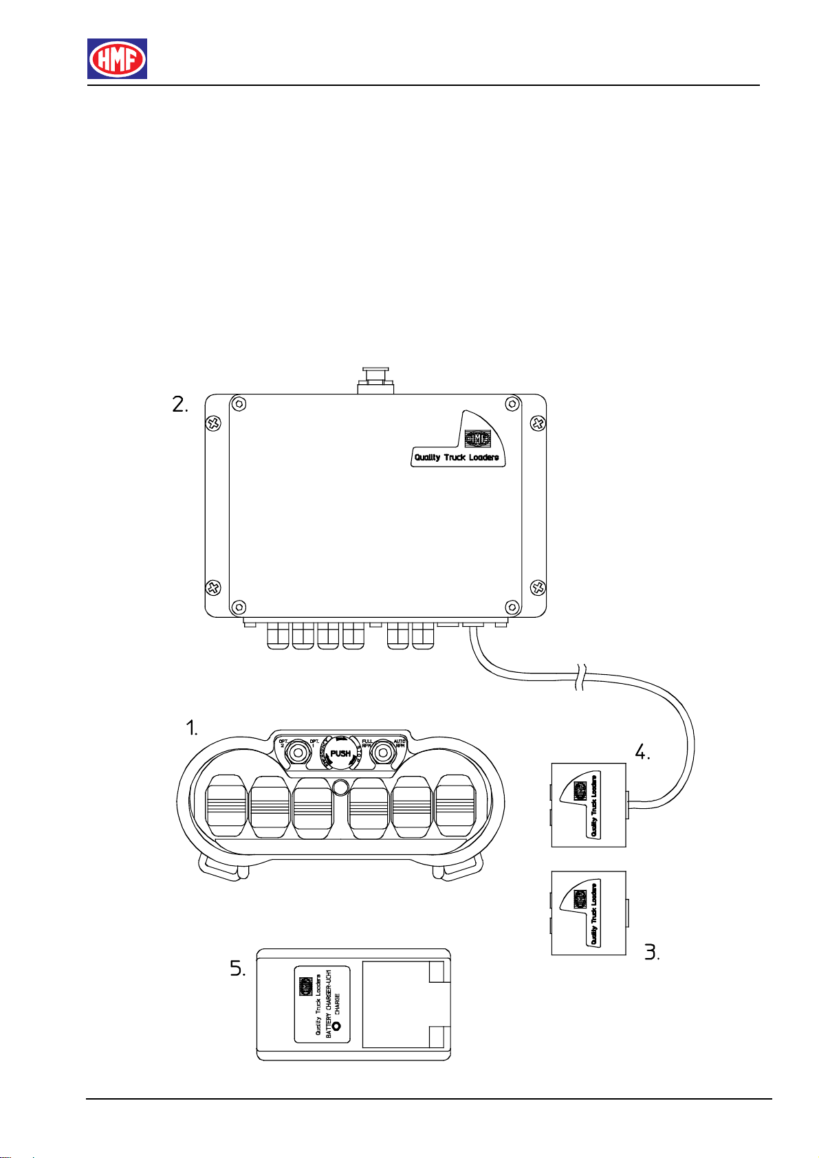
2. The Components of the IRC-System
The IRC system consists of the following components:
Remote control box with radio transmitter
Electronic box with radio receiver
Battery for the remote control box (2 pcs.)
Remote control cable (option)
Battery Charger
HMF-IRC Instruction Manual - GB
01-01 HMF TECHNICAL SERVICE DEP.
5
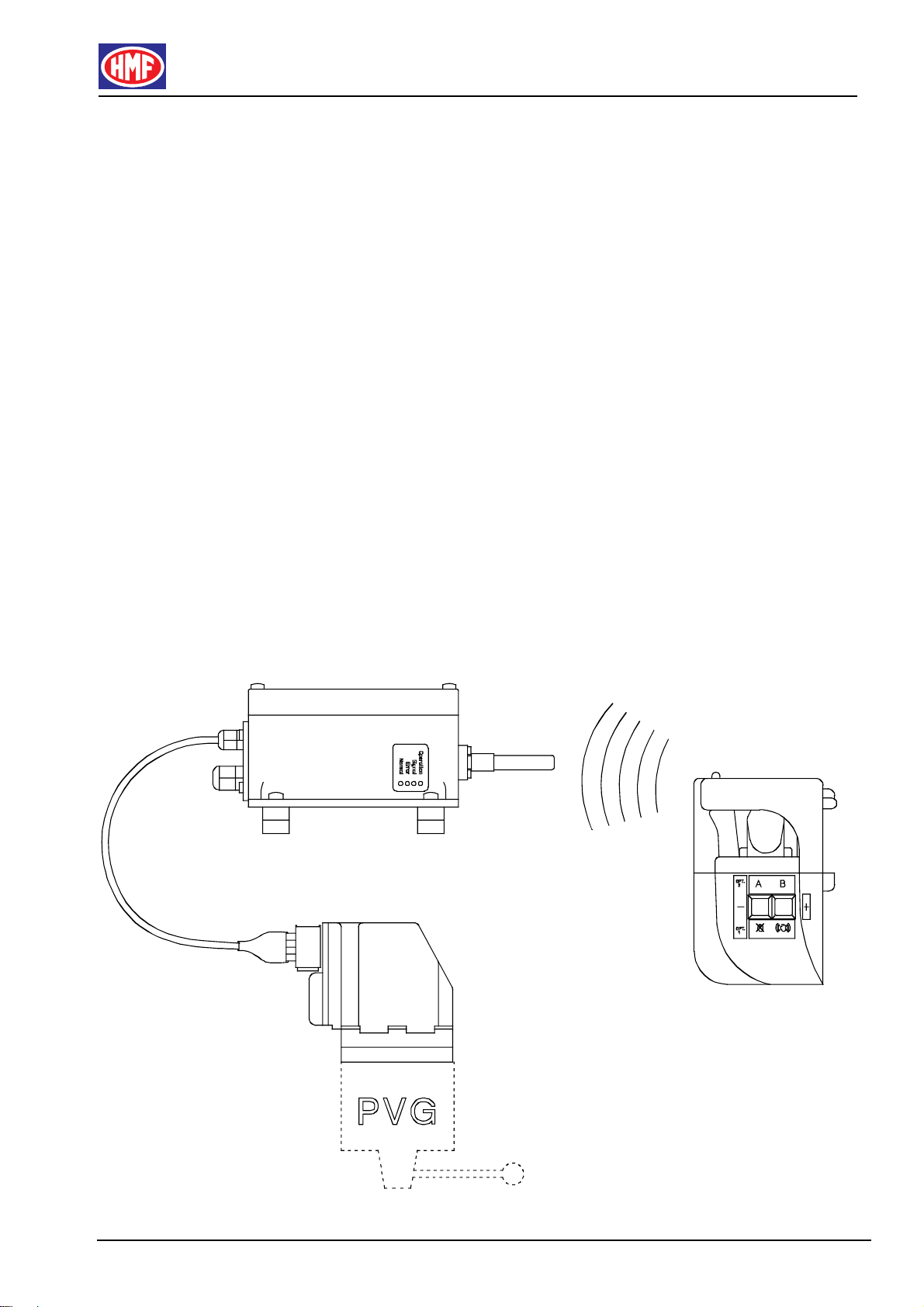
3. Description of the System
3.1 The IRC-System, general Description
The electronic box is connected to the electric activations on the valve block by
means of electric cables.
During loader operation, the control levers on the remote control box are
operated. Digitally coded control information is thus sent via radio signals to the
electronic box. The radio signals are converted to electric voltage, which is sent
to the electric activations of the valve block.
In the electric activations the electric voltage controls small hydraulic solenoid
valves. These solenoid valves control a hydraulic oil pressure, which activates
the control levers of the valve block.
The control levers on the valve block move at the same speed and in the same
direction as the control levers on the remote control box.
HMF-IRC Instruction Manual - GB
01-01 HMF TECHNICAL SERVICE DEP.
6
3.2 IRC-Remote Control Box
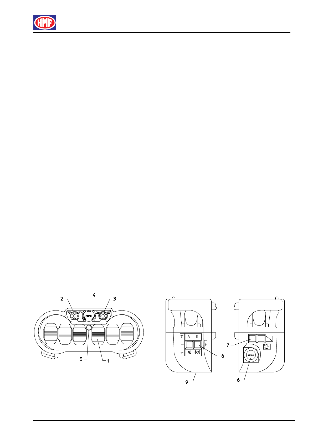
3.2.1 General Description of the Remote Control Box
The remote control box can be equipped with up to 6 control levers (pos. 1)
depending on how many loader functions are to be operated.
The left tumbler switch (pos. 2) and the right tumbler switch (pos. 3) for
operating extra functions are placed in front of the control levers. Please note:
extra functions related to the engine control of the vehicle, are only active when
the vehicle body builder has carried out the necessary electric connections.
In front of the control levers there is also a stop button (pos. 4) as well as an
indicator lamp (pos. 5). The indicator lamp as well as the built-in buzzer
currently keep the operator informed of the functional condition of the system.
On the right side of the remote control box is built in a key switch (pos. 6). The
press buttons (pos. 7) remote control functions in the RCL controller.
On the left side of the remote control box are built in some press buttons (pos.
8) for extra functions.
The remote control box is powered by a battery (pos. 9) placed at the bottom of
the box.

HMF-IRC Instruction Manual - GB
01-01 HMF TECHNICAL SERVICE DEP.
7
3.2.2 Control Levers
The control levers have stepless activation to both sides. They are spring-
loaded and therefore they automatically go back into neutral position when they
are released.
The control levers on the valve block move at the same speed and in the same
direction as the control levers on the remote control box.
The signal from a control lever is proportional, i.e. the more it is operated
towards the extreme position, the more speed is increased on the loader
function in question.
Please note that all control levers must be in neutral position before starting up
the system.
The number of control levers depends on the number of loader functions, which
are to be remote controlled. From HMF the positioning of the individual control
lever as well as the direction of travel of the loader in relation to the direction of
travel of the control levers are determined as standard configurations.
A standard configuration can be changed by an HMF service point, if required.
3.2.2.1 Operating Symbols
Loaders equipped with IRC-system are delivered from HMF with operating
symbols labelled on the remote control box.
When changing a standard configuration, the operating symbols must be
labelled on the remote control corresponding to the lever sequence in question.
At the same time, you must state the change in this Instruction Manual by
changing one of the below sketches.
In the following pages are indicated the different standard configurations of the
remote control boxes with their corresponding operating symbols.
HMF-IRC Instruction Manual - GB
01-01 HMF TECHNICAL SERVICE DEP.
8
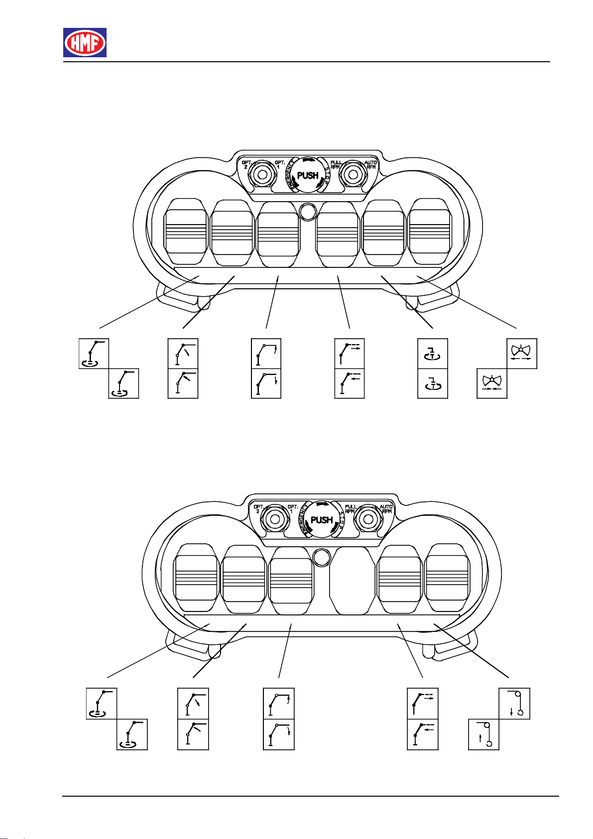
3.2.2.2 Lever Sequence, 6 Loader Functions
3.2.2.3 Lever Sequence, 5 Loader Functions

HMF-IRC Instruction Manual - GB
01-01 HMF TECHNICAL SERVICE DEP.
9
3.2.2.4 Lever Sequence, 4 Loader Functions
3.2.2.5 Lever Sequence, 6 + 2 Loader Functions

HMF-IRC Instruction Manual - GB
01-01 HMF TECHNICAL SERVICE DEP.
10
3.2.3 Press Buttons and Tumbler Switches
All press buttons and tumbler switches on the remote control box only control
“ON/OFF”-functions in the IRC-system.
3.2.3.1 Remote Control of RCL Functions
On the RCL controller, different functions can be operated by means of the
three press buttons; red, yellow and green. These functions can also be remote
controlled by means of the press buttons on the right side of the remote control
box. However, there are only two press buttons.
The functions of the green and red press buttons are operated directly, while
the function of the yellow press button is operated by pushing the left tumbler
switch to the right (opt. 1) and at the same time pushing the red press button.
The following functions are operated by means of the press buttons:
Green press button: Activation of the RCL-system / Deactivation of buzzer
Red press button: Override / Manual activation of HDL / Indication of errors
Yellow press button: Alternative function mode.
These RCL functions are thoroughly described in the RCL Instruction Manual.

HMF-IRC Instruction Manual - GB
01-01 HMF TECHNICAL SERVICE DEP.
11
3.2.3.2 Engine Throttle Control (Option)
Throttle control of the engine of the vehicle can be carried out from the remote
control box. The regulation area is between idling and a max. number of
revolutions fixed by the HMF service point and programmed in the EDC-engine
control by the supplier of the vehicle.
Operate the throttle control in the following way:
• The left tumbler switch must be in central position
• By pushing the right press button several times, the number of revolutions is
increased (+ RPM) stepwise
• By pushing the left press button several times, the number of revolutions is
decreased (- RPM) stepwise
HMF-IRC Instruction Manual - GB
01-01 HMF TECHNICAL SERVICE DEP.
12
3.2.3.3 Engine Start-Stop (Option)
The engine of the vehicle can be started and stopped from the remote control
box as follows:
• Push the left tumbler switch to the right (opt 1). The tumbler switch must be
kept in this position because it is spring-loaded and automatically goes back
into neutral position
• The engine is started by pushing the right press button
• The engine is stopped by pushing the left press button

HMF-IRC Instruction Manual - GB
01-01 HMF TECHNICAL SERVICE DEP.
13
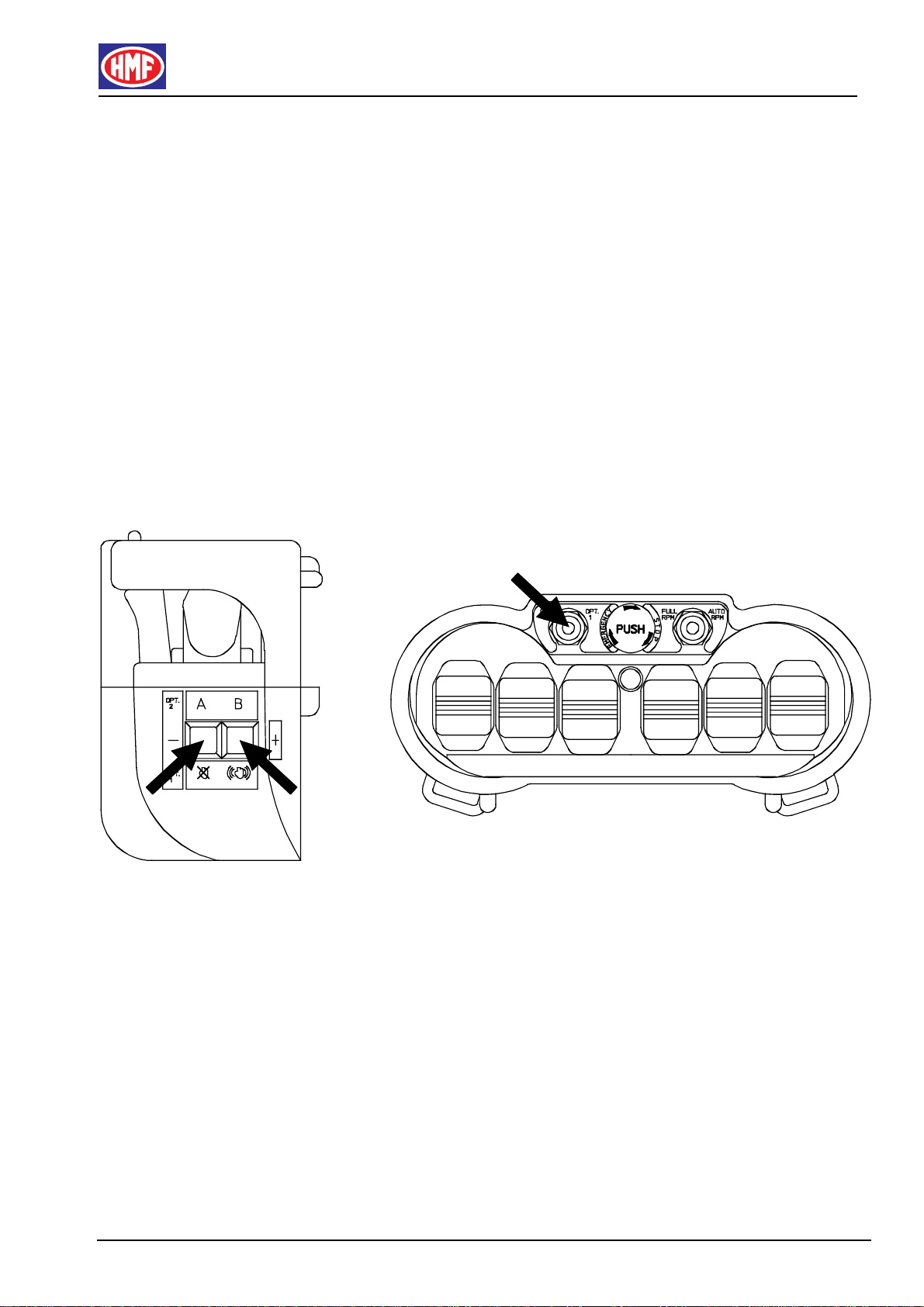
3.2.3.4 Electric Reverser Function, 7 or 8 Loader Functions
The remote control box has 6 proportionally acting control levers for operating 6
loader functions.
By means of an electric reverser function it is possible to operate up to two
more loader functions. I.e. one of the control levers can control three different
loader functions (or loader equipment).
By means of the left tumbler switch and the press buttons on the left side of the
remote control box, it is possible to change between up to three loader functions
on the control lever.
Example:
The loader is fitted with Fly-Jib. The 5th control lever operates the jib function of
the Fly-Jib and the 6th control lever operates the extension function (the two
levers to the extreme right) .
The Fly-Jib is fitted with extra valves for grab and rotator (7th and 8th function).
Operate the grab and rotator in the following way:
• Push the left tumbler switch to the left (opt. 2).
• While holding down the left press button (A), the 6th control lever changes
from Fly-Jib “extension”-function to “rotator”-function.
• While holding down the right press button (B), the 6th control lever changes
from Fly-Jib “extension”-function to “grab”-function.

HMF-IRC Instruction Manual - GB
01-01 HMF TECHNICAL SERVICE DEP.
14
If you require the 7th or 8th loader function to be activated permanently, carry out
as follows:
• Push the left tumbler switch to the left (opt. 2).
• Hold down the left press button (A) or the right press button (B) while
pushing the left tumbler switch into central position again.
Now the “grab”- or “rotator”-function is a direct function in the 6th control lever.
By repeating the procedure, the functions of the control levers are changed
back to their original functions.
HMF-IRC Instruction Manual - GB
01-01 HMF TECHNICAL SERVICE DEP.
15
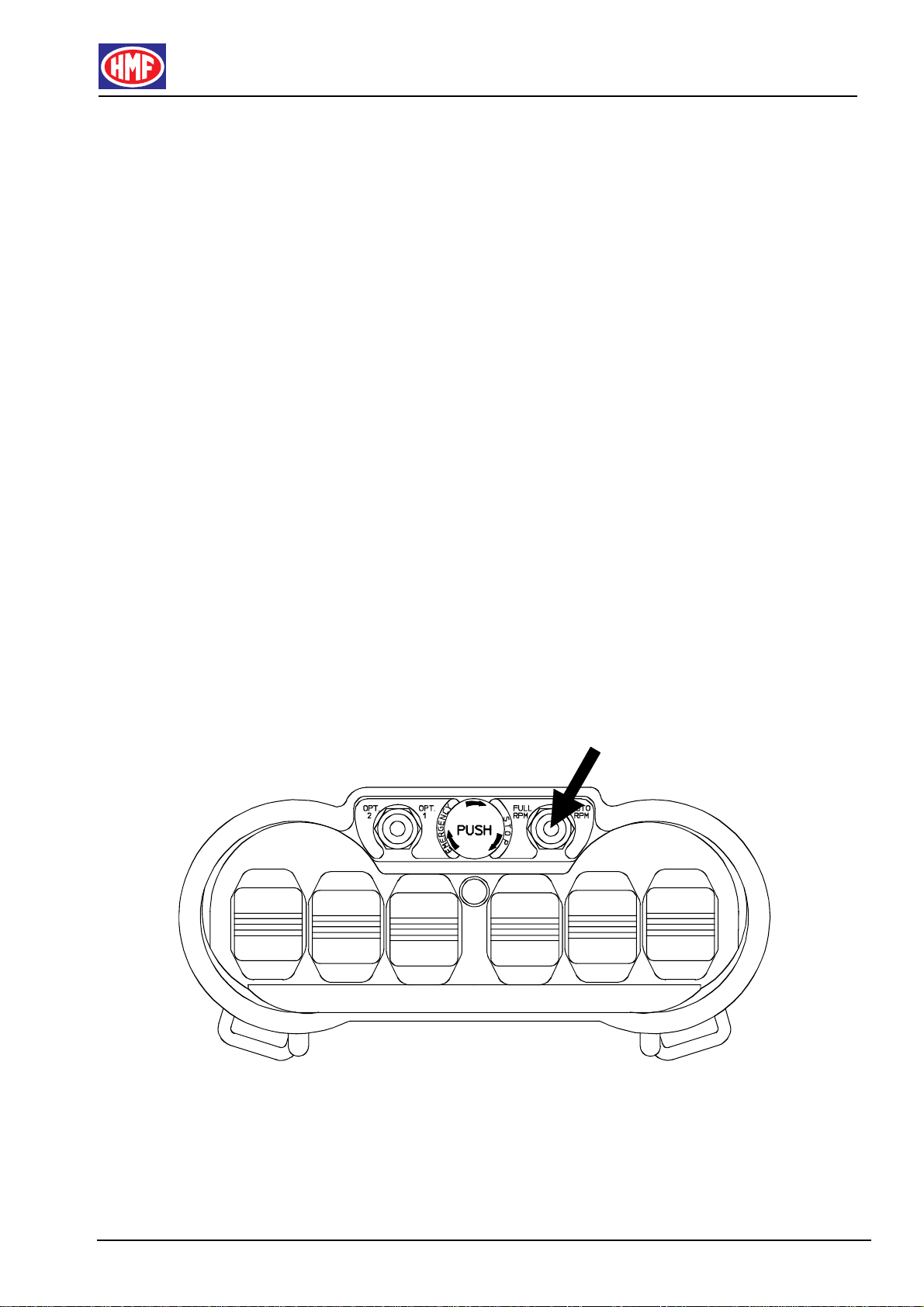
3.2.3.5 Choice of Engine Revolutions (Option)
During loader operation, the number of engine revolutions must be increased to
a fixed level (e.g. 900-1000 RPM) to optimise the capacity of the engine as well
as the working speed of the loader.
The change from the engine running idle to its number of revolutions being
increased into working level, can be remote controlled.
By means of the right tumbler switch on the remote control box, you can choose
between two types of engine revolutions.
• If the right tumbler switch is in central position, the engine revolutions are not
activated and the engine is running idle.
• If the right tumbler switch is pushed to the left (FULL RPM), the engine is
continuously running at high working speed.
• If the right tumbler switch is pushed to the right (AUTO RPM), the high
engine revolutions are automatically engaged and disengaged.
I.e. when one of the control levers is being operated, the high engine
revolutions are engaged. When the control levers are back in neutral
position, the high engine revolutions are disengaged and the engine is
running idle.
HMF-IRC Instruction Manual - GB
01-01 HMF TECHNICAL SERVICE DEP.
16
3.2.4 The Remote Control Box in Stand-By Mode
To optimise the running time of the battery as well as for safety reasons, the
remote control box is pre-programmed to go into stand-by mode after approx.
10 minutes. At the same time the indicator lamp turns off.
I.e. if there has been no operation from the remote control box for the last 10
minutes, it goes into stand-by mode, where the power consumption is very
limited.
Please note! To reactivate the remote control box, push the green press
button.
3.3 IRC-Electronic Box
A radio receiver is built into the electronic box, which by means of the external
antenna receives radio signals from the remote control box.
The electronic box is connected to either 12 or 24 volts power supply from the
accumulator of the vehicle. There are outputs for cable connection to the
electric activations of the valve block as well as to the RCL-system.
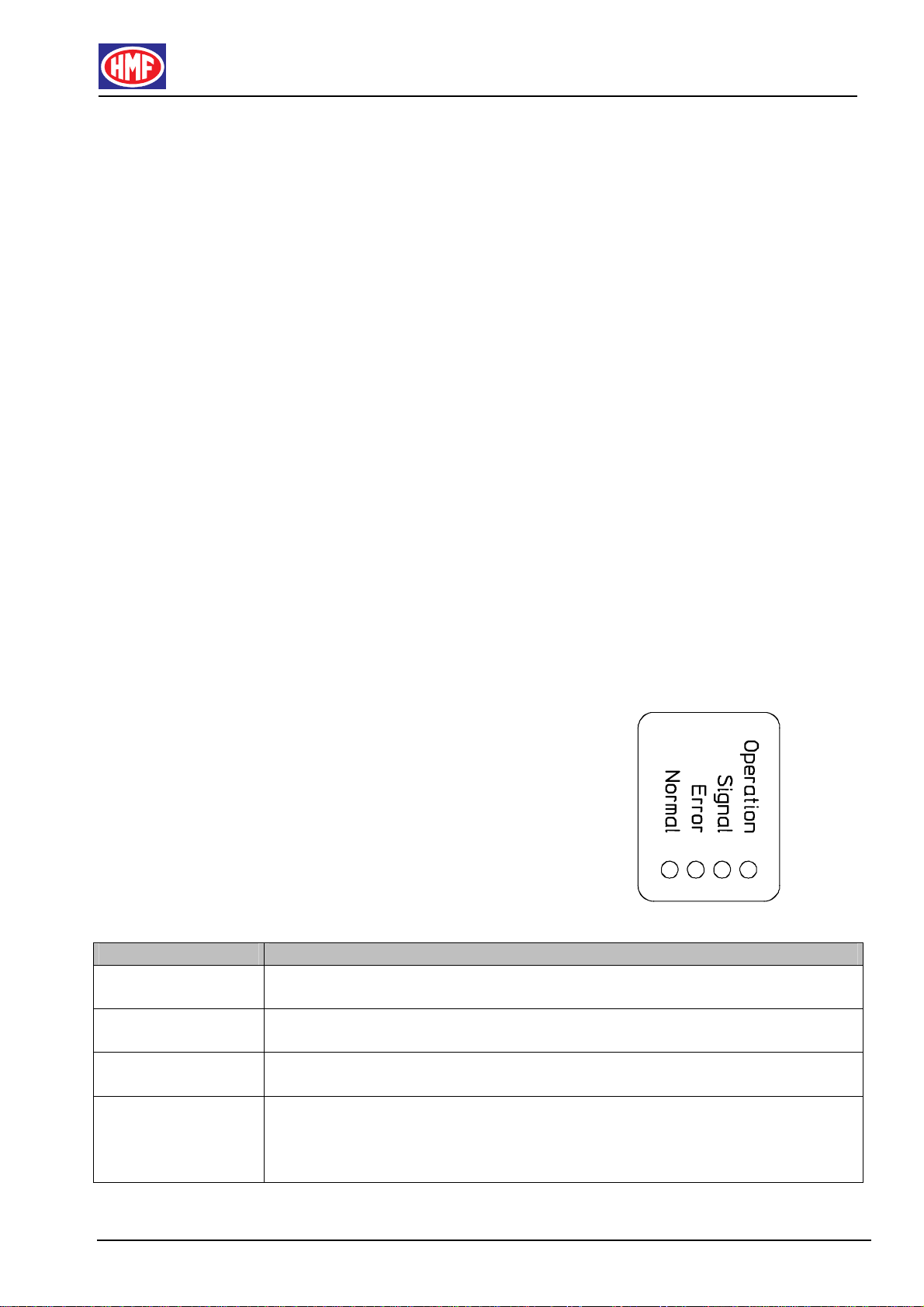
On the right side of the electronic box there is a small square with four diodes
signalling whether or not the system functions
correctly.
Diode Function
OPERATION
(yellow diode) The diode is flashing when the hydraulic pump of the vehicle has been
activated and the electric system is powered.
SIGNAL
(green diode) The diode is flashing when the remote control box is activated and the
decoder in the electronic box receives a correct radio signal.
NORMAL
(yellow diode) The diode indicates that the system is ready for operation. The diode is
lit while the SIGNAL diode is flashing.
ERROR
(red diode) When the system functions normally, the diode must be turned off. In
connection with system errors, the diode is flashing at the same
interval as the OPERATION diode. Please see chapter on
troubleshooting.

HMF-IRC Instruction Manual - GB
01-01 HMF TECHNICAL SERVICE DEP.
17
3.4 IRC-Battery and Battery Charger
Together with the IRC-system there are two rechargeable batteries. The battery
is placed at the bottom of the remote control box and can be replaced by one
single movement.
Please note: A completely charged battery works for approx. 8 hours of remote
control operation.
The battery charger must by mounted in the driver’s cab where it is protected
against dirt and humidity. The charger must via a fuse be connected to 12 or 24
volts power supply directly to the battery of the vehicle. This is how charging is
made possible, also when the ignition is turned off.
Please note: It takes approx. 3.5 hours to recharge a battery that has been
completely discharged.
3.4.1 Replacement of the Battery
The transmitter electronics in the remote control box currently monitor the
battery voltage. When the voltage comes below a certain value after approx. 8
hours of operation, the following is indicated:
• The buzzer in the remote control box gives a periodic signal during 30
seconds.
• Then the remote control box is disconnected
Now the battery has to be replaced by a recharged battery from the battery
charger.
Follow the procedure below:
• Move the loader into a safe position within the 30 seconds of the periodic
signal from the buzzer
• Turn the key switch on the right side of the remote control box into position
“0”
• Take out the discharged battery from the remote control box
• Clean the battery compartment and make sure that the pole connectors are
normally spring-loaded and not corroded
• Put a recharged battery from the battery charger up into the battery
compartment and press it into position so that it is fixed and has a good
electric connection
• Start up the remote control box according to the chapter: “Starting Up of the
IRC-System”
The radio remote control is now ready for operation.
HMF-IRC Instruction Manual - GB
01-01 HMF TECHNICAL SERVICE DEP.
18
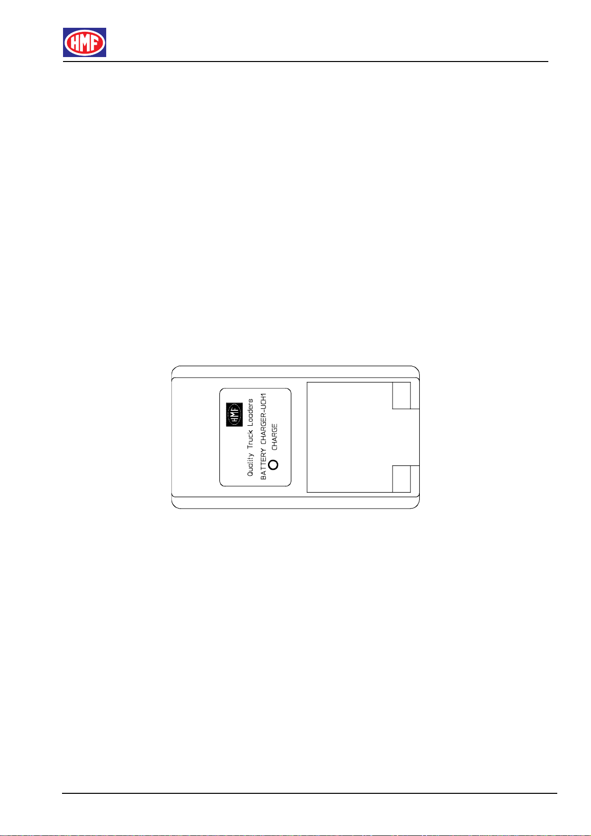
3.4.2 Charging of the Battery
Right after a discharged battery has been taken out of the remote control box, it
has to be recharged in the battery charger according to the following procedure:
• Put the battery into the battery compartment of the battery charger and press
it into position so that it is fixed and has a good electric connection.
• The green diode on the charger is lit, indicating that the battery is being
charged.
• The battery charger registers when the battery is completely charged
• After approx. 3.5 hours the charging is completed, and the green diode starts
flashing
• The battery charger now change to “maintenance charging”, ensuring that
the battery does not discharge after some time
• A completely charged battery is thus always available in the battery charger
3.4.3 Good Advice about the Battery
To ensure the longest possible working time of the batteries, the following must
be respected:
• The battery must be completely discharged before recharging it
• Do not replace the battery before the buzzer indicates that the battery has to
be recharged
• In case of low temperatures the capacity and working time of the battery are
reduced
• When at rechargeable battery is discarded, dispose of it as special waste

HMF-IRC Instruction Manual - GB
01-01 HMF TECHNICAL SERVICE DEP.
19
3.5 Remote control cable (option)
The remote control box can be connected to the electronic box by means of a
remote control cable.
Please note! The cable is not delivered together with the IRC-system as
standard.
The remote control cable can be used if the remote control box cannot
communicate with the electronic box in case of battery failure, interruption in the
radio communication, errors in radio transmitter/receiver, or the like,
The cable has an adapter in one end, which is inserted in the battery
compartment on the remote control box.
3.6 Transmitter System, Frequencies
Every time the IRC-system is started up, one out of 16 frequencies in the ISM-
band is chosen.
In the self-test phase during start up of the remote control box, the system is
testing whether the chosen frequency can be used or whether it collides with
other radio transmitters. If it cannot be used, repeat the starting up procedure
and the next frequency will be chosen.
A coded data telegram is now transmitted from the remote control box with an
address that must be in accordance with a corresponding data telegram with its
address in the electronic box at the frequency in question.
When the radio receiver has accepted the coded data telegram of the radio
transmitter, the IRC-system is ready for operation.
Table of contents
Other HMF Farm Equipment manuals


Popular Farm Equipment manuals by other brands


Packo
Packo REM/DX Series installation manual

Blue Diamond
Blue Diamond POWER RAKE Operation and maintenance manual

Land Pride
Land Pride SSB1566 Operator's manual

Hardi
Hardi RANGER 2500 TR2 instruction manual

Plasson
Plasson Super Easy Start Adjustable operating instructions

Westfalia
Westfalia N1C-JY-700 instruction manual

Serafin
Serafin Ultisow Operator's manual

Toro
Toro Dingo TX 22306 Operator's manual

GREAT PLAINS
GREAT PLAINS Ultra-Till I 3030 Series Operator's manual

Chore-Time
Chore-Time LIBERTY Feeding System Installation and operator's manual

Redexim
Redexim 7117 user manual

Priefert
Priefert RC98SCOREAI operating instructions