HMS Anybus Wireless Bolt Serial User manual

Anybus®Wireless Bolt Serial™
USER MANUAL
SCM-1202-143
Version 2.0
Publicaon date 2022-04-07
ENGLISH

Important User Informaon
Disclaimer
The informaon in this document is for informaonal purposes only. Please inform HMS Networks of any
inaccuracies or omissions found in this document. HMS Networks disclaims any responsibility or liability for any
errors that may appear in this document.
HMS Networks reserves the right to modify its products in line with its policy of connuous product
development. The informaon in this document shall therefore not be construed as a commitment on the
part of HMS Networks and is subject to change without noce. HMS Networks makes no commitment to update
or keep current the informaon in this document.
The data, examples and illustraons found in this document are included for illustrave purposes and are only
intended to help improve understanding of the funconality and handling of the product. In view of the wide
range of possible applicaons of the product, and because of the many variables and requirements associated
with any parcular implementaon, HMS Networks cannot assume responsibility or liability for actual use
based on the data, examples or illustraons included in this document nor for any damages incurred during
installaon of the product. Those responsible for the use of the product must acquire sucient knowledge in
order to ensure that the product is used correctly in their specic applicaon and that the applicaon meets all
performance and safety requirements including any applicable laws, regulaons, codes and standards. Further,
HMS Networks will under no circumstances assume liability or responsibility for any problems that may arise as
a result from the use of undocumented features or funconal side eects found outside the documented scope
of the product. The eects caused by any direct or indirect use of such aspects of the product are undened and
may include e.g. compability issues and stability issues.
Copyright © 2021 HMS Networks
Contact Informaon
Postal address:
Box 4126
300 04 Halmstad, Sweden
E-Mail: inf[email protected]

Table of Contents
1. Preface .................................................................................................................................. 1
1.1. About This Document ........................................................................................................ 1
1.2. Document Convenons ..................................................................................................... 1
1.3. Trademarks ..................................................................................................................... 2
2. Safety .................................................................................................................................... 3
2.1. General Safety ................................................................................................................. 3
2.2. Intended Use ................................................................................................................... 3
3. Preparaon ............................................................................................................................ 4
3.1. Support and Resources ...................................................................................................... 4
3.2. Network Environment ....................................................................................................... 4
3.3. Placement ....................................................................................................................... 4
3.4. When to Use Bluetooth or WLAN ........................................................................................ 4
3.5. Bluetooth Limitaons ........................................................................................................ 4
3.6. I/O-Data Cycle Time Consideraons ..................................................................................... 5
4. Installaon ............................................................................................................................. 6
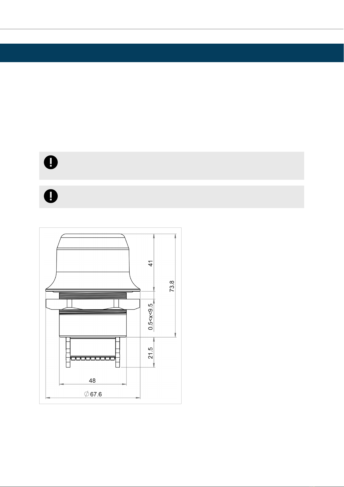
4.1. Mechanical Installaon ...................................................................................................... 6
4.2. Connector ....................................................................................................................... 7
4.3. Cabling ........................................................................................................................... 8
4.4. Reset Buon .................................................................................................................... 9
5. Conguraon ......................................................................................................................... 10
5.1. Bolt Serial Built-In Web Interface ........................................................................................ 10
5.2. Access the Built-In Web Interface ....................................................................................... 11
5.2.1. Required IP Address Sengs ...................................................................................... 11
5.2.2. Log In to the Built-In Web Interface ............................................................................. 12
5.3. To Save and Reboot ......................................................................................................... 13
5.4. Factory Default Sengs .................................................................................................... 14
5.5. Conguraon Methods ..................................................................................................... 15
5.6. Wireless Conguraon via Access Point Unit ......................................................................... 15
5.7. Conguraon with Easy Cong ........................................................................................... 16
5.7.1. Available Easy Cong Modes ...................................................................................... 16
5.7.2. Easy Cong Modes Time Consideraons ....................................................................... 16
5.7.3. How to Acvate an Easy Cong Mode .......................................................................... 17
5.8. Conguraon with AT Commands ....................................................................................... 18
5.8.1. Enable Fast Roaming with AT Commands ...................................................................... 19
5.8.2. Digital Input ............................................................................................................ 19
5.8.3. Add Addional WLAN Channels with AT Commands ....................................................... 20
5.9. Congure Sengs in the Built-In Web Interface ..................................................................... 22
5.9.1. Network Sengs ..................................................................................................... 22
5.9.2. Layer 3 IP Forward Connecvity Consideraons ............................................................. 23
5.9.3. WLAN Sengs General ............................................................................................. 24
5.9.4. WLAN Sengs for Client ........................................................................................... 25
5.9.5. WLAN Roaming ....................................................................................................... 25
5.9.6. WLAN Channels and World Mode ............................................................................... 26
5.9.7. WLAN Sengs for Access Point .................................................................................. 27
5.9.8. WLAN Advanced Sengs .......................................................................................... 28
5.9.9. Bluetooth Sengs General ........................................................................................ 29
5.9.10. Bluetooth Sengs for PANU Mode ............................................................................ 30
5.9.11. Bluetooth Sengs for NAP Mode .............................................................................. 31
Anybus® Wireless Bolt Serial™
SCM-1202-143 2.0

5.9.12. Set Up Serial Communicaon ................................................................................... 32
5.9.13. Serial Communicaon ............................................................................................. 35
5.9.14. System Sengs ...................................................................................................... 36
6. Use Cases .............................................................................................................................. 37
6.1. Bolt Serial Point-to-Point Installaon ................................................................................... 37
6.2. Set Up Wireless Infrastructure ........................................................................................... 38
6.3. Installing Mulple Bolt Serial Units ..................................................................................... 40
6.4. Installing on a Modbus Network ......................................................................................... 41
6.5. Installing Using the Modbus TCP to RTU Gateway Funcon ...................................................... 42
6.6. Bolt Serial TCP/IP Socket Protocol Descripon ....................................................................... 43
7. Verify Operaon ..................................................................................................................... 44
7.1. Network Connecon Status ............................................................................................... 44
8. Maintenance ......................................................................................................................... 45
8.1. Firmware Update ............................................................................................................ 45
8.2. Sengs Backup ............................................................................................................... 47
8.2.1. Create Sengs Backup File ........................................................................................ 47
8.2.2. Restore Sengs From Backup File ............................................................................... 47
9. Troubleshoong ..................................................................................................................... 48
9.1. Reset Buon ................................................................................................................... 48
9.2. Recovery Mode ............................................................................................................... 49
9.3. Reset to Factory Default .................................................................................................... 50
10. Technical Data ...................................................................................................................... 52
10.1. Technical Specicaons ................................................................................................... 52
11. Reference Guides .................................................................................................................. 54
11.1. RS232/RS485 Electrical Connecon ................................................................................... 54
11.2. Wireless Technology Basics .............................................................................................. 55
11.3. Radio Antenna Paerns .................................................................................................. 56
Anybus® Wireless Bolt Serial™
SCM-1202-143 2.0

1. Preface
1.1. About This Document
This document describes how to install and congure Anybus® Wireless Bolt Serial™.
For addional documentaon and soware downloads, FAQs, troubleshoong guides and technical support,
please visit www.anybus.com/support.
1.2. Document Convenons
Lists
Numbered lists indicate tasks that should be carried out in sequence:
1. First do this
2. Then do this
Bulleted lists are used for:
• Tasks that can be carried out in any order
• Itemized informaon
User Interacon Elements
User interacon elements (buons etc.) are indicated with bold text.
Program Code and Scripts
Program code and script examples
Cross-References and Links
Cross-reference within this document: Document Convenons (page 1)
External link (URL): www.anybus.com
Safety Symbols
DANGER
Instrucons that must be followed to avoid an imminently hazardous situaon which, if not avoided,
will result in death or serious injury.
WARNING
Instrucons that must be followed to avoid a potenal hazardous situaon that, if not avoided, could
result in death or serious injury.
CAUTION
Instrucon that must be followed to avoid a potenal hazardous situaon that, if not avoided, could
result in minor or moderate injury.
IMPORTANT
Instrucon that must be followed to avoid a risk of reduced funconality and/or damage to the
equipment, or to avoid a network security risk.
Preface Anybus® Wireless Bolt Serial™
SCM-1202-143 2.0 Page 1 of 60

Informaon Symbols
NOTE
Addional informaon which may facilitate installaon and/or operaon.
TIP
Helpful advice and suggesons.
1.3. Trademarks
Anybus® is a registered trademark and Wireless Bolt Serial™ is a trademark of HMS Networks AB.
All other trademarks are the property of their respecve holders.
Anybus® Wireless Bolt Serial™Trademarks
Page 2 of 60 SCM-1202-143 2.0

2. Safety
2.1. General Safety
CAUTION
This equipment emits RF energy in the ISM (Industrial, Scienc, Medical) band. Make sure that all
medical devices used in proximity to this equipment meet appropriate suscepbility specicaons
for this type of RF energy.
CAUTION
This equipment contains parts that can be damaged by electrostac discharge (ESD). Use ESD
prevenon measures to avoid damage.
CAUTION
Minimum temperature rang of the cable to be connected to the eld wiring terminals, 90 °C.
CAUTION
Use copper wire only for eld wiring terminals.
CAUTION
This equipment is recommended for use in both industrial and domesc environments. For industrial
environments it is mandatory to use the funconal earth connecon to comply with immunity
requirements. For domesc environments the funconal earth must be used if a shielded Ethernet
cable is used, in order to meet emission requirements.
2.2. Intended Use
The intended use of this equipment is as a communicaon interface and gateway. The equipment receives and
transmits data on various physical levels and connecon types.
If this equipment is used in a manner not specied by the manufacturer, the protecon provided by the
equipment may be impaired.
Safety Anybus® Wireless Bolt Serial™
SCM-1202-143 2.0 Page 3 of 60

3. Preparaon
3.1. Support and Resources
For addional documentaon and soware downloads, FAQs, troubleshoong guides and technical support,
please visit www.anybus.com/support.
TIP
Have the product arcle number available, to search for the product specic support web page. You
nd the product arcle number on the product cover.
3.2. Network Environment
Ensure that you have all the necessary informaon about the capabilies and restricons of your local network
environment before installaon.
3.3. Placement
Antenna Consideraons
The characteriscs of the internal antenna should be considered when choosing the placement and orientaon
of the unit.
See also Internal Antenna Characteriscs.
Required Distance Between Devices
For opmal recepon, wireless devices require a zone between them clear of objects that could otherwise
obstruct or reect the signal. To avoid signal interference, a minimum distance of 50 cm between the devices
should be observed.
See Wireless Technology Basics (page 55).
3.4. When to Use Bluetooth or WLAN
Use Bluetooth when:
• The wireless link has an Anybus Wireless Bolt or Anybus Wireless Bridge II at both ends.
• An interrupon-free connecon is more important than data throughput speed.
• Interference robustness is important, e.g. in an industrial environment.
• A Pronet I/O cycle me or EtherNet/IP RPI of 64 ms or more is acceptable.
Use WLAN when:
•Connecng to other types of wireless devices or a WLAN infrastructure.
• High data throughput speed is more important than connecon reliability.
• Large le transfers are expected.
• WLAN channel frequency planning is possible.
• A low Pronet I/O cycle me or EtherNet/IP RPI is desired.
3.5. Bluetooth Limitaons
Due to dierent implementaons of Bluetooth by dierent manufacturers, Bluetooth PAN (Personal Area
Network) may not work with some devices.
WLAN 5 GHz cannot be used at the same me as WLAN 2.4 GHz or Bluetooth.
Anybus® Wireless Bolt Serial™Preparaon
Page 4 of 60 SCM-1202-143 2.0

3.6. I/O-Data Cycle Time Consideraons
Based on recommendaons from industrial equipment suppliers, such as Rockwell and Siemens, use the
following minimum I/Odata cycle mes for PROFINET and EtherNet/IP networks:
• Wireless link Point-to-Point with Bluetooth PANU-PANU or Wi-Fi Access Point to Staon: 32 ms
• Wireless link with Access Point and up to 4 wireless clients/staons, Bluetooth or Wi-Fi: 64 ms
I/O-Data Cycle Time Consideraons Anybus® Wireless Bolt Serial™
SCM-1202-143 2.0 Page 5 of 60

4. Installaon
4.1. Mechanical Installaon
Placement
• The device is intended to be mounted on top of a machine or cabinet through an M50 (50.5mm) hole using
the included sealing ring and nut.
• The top mounng surface, in contact with the sealing, must be at with a nish equivalent to Ra 3.2 or ner
and cleaned and free from oils and greases.
Installaon
IMPORTANT
Make sure that the sealing ring is correctly placed in the circular groove in the top part of the
housing before ghtening the nut.
IMPORTANT
Always hold the BOTTOM part of the unit when unghtening the nut, not the top part (the cap).
Tightening torque: 5 Nm ±10 %
All measurements are in mm.
Figure 1. Installaon drawing
Anybus® Wireless Bolt Serial™Installaon
Page 6 of 60 SCM-1202-143 2.0

4.2. Connector
The 18-pin connector is common for several models of the Anybus Wireless Bolt. Some pins may have a dierent
funcon depending on model. Unused pins should not be connected.
Figure 2. 18-Pin connector
The locaon of the RESET buon can be used as a reference for the pin numbering when the connector is
aached to the Bolt Serial. Pin 1 will be the pin closest to the RESET buon.
NOTE
The Ethernet interface is intended for conguraon purposes only. Bolt Serial is not designed for
permanent Ethernet communicaon.
NOTE
A and B marking diers between dierent devices, in this product A is TX-/RX- or D- and B is TX+/RX+
or D+.
For informaon about the correct connecon type and terminaon, refer to RS232/RS485 Electrical Connecon
(page 54).
Pin Name Descripon
1 VIN Power + (9–30 V)
2 GND Power Ground
3 DI Digital input + (9–30 V)
4 DI_GND Digital input ground
5 ETN_RD+ Ethernet receive + (white/orange)
6 ETN_RD- Ethernet receive - (orange)
7 ETN_TD- Ethernet transmit - (green)
8 ETN_TD+ Ethernet transmit + (white/green)
9 RS485_B RS-485 B Line
10 FE/Shield Ethernet: Funconal Earth
Serial and CAN: Funconal Earth and Shield
11 RS232_TXD RS-232 Transmit
12 RS485_A/RS232_RXD RS-485 A Line / RS-232 Receive
13 RS232_RTS RS-232 Request To Send (Not used for Wireless Bolt Serial.)
14 RS232_CTS RS-232 Clear To Send (Not used for Wireless Bolt Serial.)
15 ISO_5V Isolated 5 V for serial interface
16 RS232_GND/RS485_GND Isolated Ground for Serial interface
17 CAN_L CAN Low (Not used for Wireless Bolt Serial.)
18 CAN_H CAN High (Not used for Wireless Bolt Serial.)
Connector Anybus® Wireless Bolt Serial™
SCM-1202-143 2.0 Page 7 of 60

Note:
• Use RS-485 when connecng mulple devices to a Bolt Serial.
• The Ethernet wire colors refer to the T568A standard.
• If using a shielded Ethernet cable the shield must be unconnected.
• RS-232 and RS-485 cannot be used at the same me.
• Use terminaon for RS-485 and CAN when required.
• RS485 Common signal reference ground (SC) is the RS485_GND pin.
4.3. Cabling
Before You Begin
NOTE
When using Easy Cong Modes, the Bolt Serial that is to be congured as a Client does not need to
be connected to the Ethernet wires. Only power and Serial wiring are used.
NOTE
To maintain signal integrity, low emission and high immunity to EMI, untwist the twisted pair cable
as lile as possible.
Procedure
Create connector cable for Bolt Serial
1. Cut o one of the connectors on a standard Cat5e or Cat6 Ethernet cable.
2. Strip o about 40 mm (1½ inch) of the cable jacket and untwist the orange, orange/white, green and
green/white wires.
The shield and the other wires are not used.
3. Strip o about 7 mm (¼ inch) of the isolaon on each wire.
4. Push the pin spring release next to each socket on the connector and insert the correct wire end according
to Connector (page 7).
5. Connect the wires from the Serial device to the connector in the same way as the Ethernet wiring.
6. Connect the wires from the power supply to the connector in the same way as the Ethernet wiring.
NOTE
Ensure that polarity is not reversed.
Anybus® Wireless Bolt Serial™Cabling
Page 8 of 60 SCM-1202-143 2.0

4.4. Reset Buon
Figure 3. Reset buon
The Reset buon is located on the boom of the Bolt Serial.
Reset Buon Anybus® Wireless Bolt Serial™
SCM-1202-143 2.0 Page 9 of 60

5. Conguraon
5.1. Bolt Serial Built-In Web Interface
The Bolt Serial built-in web interface is used to congure, maintain and troubleshoot the Bolt Serial. Parameters
can be set individually or using pre-congured Easy Cong modes.
The web interface is accessed by poinng a web browser to the IP address of the unit.
The default address is 192.168.0.99.
See also Access the Built-In Web Interface (page 11).
Figure 4. System Overview page example
The System Overview page shows current sengs and network connecon status.
The Help page describes the AT commands that can be used for advanced conguraon.
Anybus® Wireless Bolt Serial™Conguraon
Page 10 of 60 SCM-1202-143 2.0

5.2. Access the Built-In Web Interface
5.2.1. Required IP Address Sengs
To be able to access the Bolt Serial built-in web interface you may need to adjust the IP sengs, choose one of
the following methods.
The Bolt Serial default IP address is 192.168.0.99.
Opon 1 - Set a Stac IP Address on Your PC
On the PC accessing the Bolt Serial built-in web interface, set a stac IP address within the same IP address range
as the Bolt Serial IP address.
Note that when you change to a stac IP address on your PC, internet access is lost.
Opon 2 - Change the IP Address on the Bolt Serial Ethernet port
Use the soware applicaon HMS IPcong to nd and change the IP address on the Bolt Serial Ethernet port, to
one within the same IP address range as the PC accessing the Bolt Serial built-in web interface.
To download the installaon les, please visit www.anybus.com/support and enter the product arcle number to
search for the Bolt Serial support web page. You nd the product arcle number on the product cover.
Result
Now you can enter the Bolt Serial IP address in your web browser and search to access the built-in web interface
login page.
See Log In to the Built-In Web Interface (page 12).
Access the Built-In Web Interface Anybus® Wireless Bolt Serial™
SCM-1202-143 2.0 Page 11 of 60

5.2.2. Log In to the Built-In Web Interface
The Bolt Serial built-in web interface can be accessed from a standard web browsers.
Before You Begin
IMPORTANT
Before installing Bolt Serial on a network, change the default administrator password.
IMPORTANT
Before installing the Bolt Serial on a network, change the Bolt Serial default username and password.
NOTE
The Bolt Serial comes with a default username and password. The default username is admin,
wrien in lowercase leers. You nd the default password on the Bolt Serial product housing.
NOTE
The Bolt Serial default IP address is 192.168.0.99.
Procedure
Login to the Bolt Serial built-in web interface
1. Open a web browser.
2. Click to select the Address bar and enter the Bolt Serial IP address.
Figure 5. Enter IP address in web browser
3. Press Enter.
The built-in web interface login screen appears.
4. Enter the Password and click Sign in.
Figure 6. Built-in web interface login screen
Anybus® Wireless Bolt Serial™Access the Built-In Web Interface
Page 12 of 60 SCM-1202-143 2.0

Result
You are logged in to the System Overiew page.
Figure 7. System Overiew page
5.3. To Save and Reboot
Cancel Changes
To cancel changes you have made to the sengs:
• In the le sidebar menu, click Cancel All Changes.
To restore sengs, see Restore Sengs From Backup File (page 47).
Apply Changes
• To apply changes, click Save and Reboot in the le sidebar menu.
Bolt Serial restarts for the changes to take eect.
To Save and Reboot Anybus® Wireless Bolt Serial™
SCM-1202-143 2.0 Page 13 of 60

5.4. Factory Default Sengs
Any one of these acons will restore the factory default sengs:
Default Network Sengs
IP Assignment Stac
IP Address 192.168.0.99
Subnet Mask 255.255.255.0
Default Gateway 192.168.0.99
Internal DHCP Server Disabled
DHCP Interfaces All
Default WLAN Sengs
Operang Mode Client
Channel Bands 2.4 GHz & 5 GHz
Authencaon Mode WPA/WPA2–PSK
Channel Auto
Bridge Mode Layer 3 IP forward
Default Bluetooth Sengs
Operang Mode PANU (Client)
Local Name [generated from MAC address]
Connectable No
Discoverable No
Security Mode Just works
Default Serial Sengs
Operang Mode RS232
Baud Rate 57600 bits/s
Data bits 8
Stop bits 1
Parity No parity
Modbus opmizaon O
TCP Mode Server
Modbus Gateway Mode Disabled
TCP port 5005
Anybus® Wireless Bolt Serial™Factory Default Sengs
Page 14 of 60 SCM-1202-143 2.0

5.5. Conguraon Methods
There are dierent methods available for conguring the Bolt Serial.
Built-In Web Interface Sengs
Bolt Serial can be congured via the sengs in the built-in web interface.
See Congure Sengs in the Built-In Web Interface (page 22).
Easy Cong Modes
Bolt Serial can be congured using one of the pre-congured Easy Cong modes.
See Conguraon with Easy Cong (page 16).
AT Commands
Advanced conguraon can be carried out by issuing AT (modem) commands through the web interface or over
a Telnet or RAW TCP connecon to port 8080.
For more informaon about how to use the AT commands, navigate to the built-in web interface Help page or
see the AT Commands Reference Guide.
See also Conguraon with AT Commands (page 18).
5.6. Wireless Conguraon via Access Point Unit
Conguraon of Wireless Bolt and Bridge Clients can be performed wirelessly, via a PC connected to the Wireless
Bolt or Bridge Access Point.
When connecon is established via the wireless interface, the Wireless Bolt or Bridge Client does not need to be
connected with an Ethernet cable during conguraon.
Conguraon Methods Anybus® Wireless Bolt Serial™
SCM-1202-143 2.0 Page 15 of 60

5.7. Conguraon with Easy Cong
5.7.1. Available Easy Cong Modes
Bolt Serial may be congured using one of the pre-congured Easy Cong modes.
NOTE
By default, the unit starts in Easy Cong Mode 4. The unit awaits automac conguraon during 120
seconds or unl receiving a conguraon.
NOTE
To cancel Easy Cong mode 11, the unit must be reset to factory default sengs. See Reset to
Factory Default (page 50)
Table 1. Easy Cong modes
EC Role Descripon
1Bluetooth PANU Used for seng up point-to-point communicaon.
The unit scans for another unit in Cong Mode 4. The unit listens for 40 seconds or unl a conguraon is established.
When a unit in mode 4 is detected: The scanning unit congures itself as a Bluetooth PANU Client, sends a connecon
conguraon to the detected unit, and restarts. The detected unit restarts and aempt to connect to the rst unit as a
PANU Client.
2N/A Reset conguraon to factory defaults.
3N/A Reset IP sengs to factory defaults.
4Client Congure units in mode 4 as Clients.
Wait for automac conguraon. The unit listens for 120 seconds or unl receiving a conguraon.
When mode 4 is used with mode 1, 5 or 6, Serial Sengs TCP Mode Client is acvated automacally.
5WLAN AP The unit scans for other units in Cong Mode 4 and congure them as Clients. Timeout occur aer 120 seconds.
Restart as Access Point and connect Clients.6Bluetooth NAP
11 (any) Enable PROFIsafe mode. The unit is locked in PROFIsafe mode.
No other conguraon sengs are changed.
The Easy Cong modes are also described when selected in the built-in web interface. See How to Acvate an
Easy Cong Mode (page 17).
5.7.2. Easy Cong Modes Time Consideraons
Table 2. Easy Cong modes me consideraons
Mode Timeout
1 and 9 The unit listens for 40 seconds or unl a conguraon is established.
4 The unit listens for 120 seconds or unl receiving a conguraon.
5, 6, 7 and 8 The unit scans for 120 seconds, then meout occur.
Anybus® Wireless Bolt Serial™Conguraon with Easy Cong
Page 16 of 60 SCM-1202-143 2.0
Other manuals for Anybus Wireless Bolt Serial
1
This manual suits for next models
2
Table of contents