manuals.online logo
Brands
  1. Home
  2. •
  3. Brands
  4. •
  5. Hobart
  6. •
  7. Portable Generator
  8. •
  9. Hobart Hobart 400 HZ User manual

Hobart Hobart 400 HZ User manual

This manual suits for next models

4

Other Hobart Portable Generator manuals

Hobart 60CU20 Setup guide

Hobart

Hobart 60CU20 Setup guide

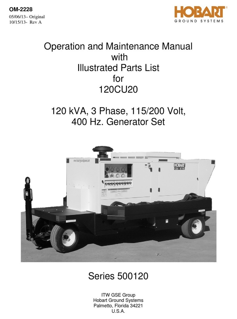
Hobart 120CU20 Setup guide

Hobart

Hobart 120CU20 Setup guide

Hobart 140GT17P Setup guide

Hobart

Hobart 140GT17P Setup guide

Hobart 283782 User manual

Hobart

Hobart 283782 User manual

Hobart 100D20 Setup guide

Hobart

Hobart 100D20 Setup guide

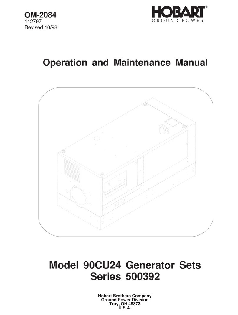
Hobart 90CU24 User manual

Hobart

Hobart 90CU24 User manual

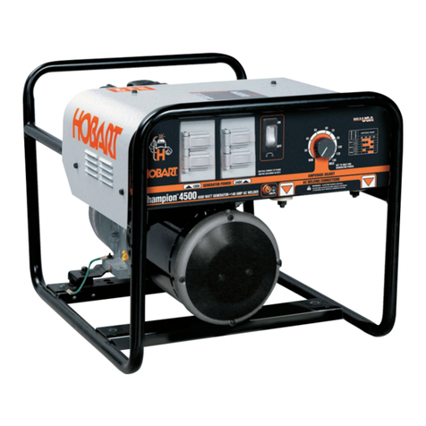
Hobart Champion 4500 User manual

Hobart

Hobart Champion 4500 User manual

Hobart 6921 Series User manual

Hobart

Hobart 6921 Series User manual

Hobart 9OC24S User manual

Hobart

Hobart 9OC24S User manual

Hobart GPU-600 Series User manual

Hobart

Hobart GPU-600 Series User manual

Popular Portable Generator manuals by other brands

Comdel CLF5000/PLL manual

Comdel

Comdel CLF5000/PLL manual

Outsunny 84F-006V80 Using instruction

Outsunny

Outsunny 84F-006V80 Using instruction

Icel Manaus GV-2015 User's operation manual

Icel Manaus

Icel Manaus GV-2015 User's operation manual

Stat-X 30E owner's manual

Stat-X

Stat-X 30E owner's manual

Metallwarenfabrik Gemmingen Eisemann T 18000 E operating instructions

Metallwarenfabrik Gemmingen

Metallwarenfabrik Gemmingen Eisemann T 18000 E operating instructions

Alpha ACX3100i quick start guide

Alpha

Alpha ACX3100i quick start guide

HERON 8896140 Translation of the original user manual

HERON

HERON 8896140 Translation of the original user manual

SEERS STF-V11 Operator's manual

SEERS

SEERS STF-V11 Operator's manual

JOYZIS BS100 Faq

JOYZIS

JOYZIS BS100 Faq

LIPOWER G1600 user manual

LIPOWER

LIPOWER G1600 user manual

Panasonic YD-350GL4 operating instructions

Panasonic

Panasonic YD-350GL4 operating instructions

RUNHOOD HE1200-UK user manual

RUNHOOD

RUNHOOD HE1200-UK user manual

Kohler 20EORZ Operation

Kohler

Kohler 20EORZ Operation

Powerhorse 83171 owner's manual

Powerhorse

Powerhorse 83171 owner's manual

ETQ TG4000 owner's manual

ETQ

ETQ TG4000 owner's manual

Briggs & Stratton 40265 Illustrated parts list

Briggs & Stratton

Briggs & Stratton 40265 Illustrated parts list

evertz 7700 Series manual

evertz

evertz 7700 Series manual

Firefly Cygnus CYG2400/460/24 user manual

Firefly

Firefly Cygnus CYG2400/460/24 user manual

manuals.online logo
manuals.online logoBrands
  • About & Mission
  • Contact us
  • Privacy Policy
  • Terms and Conditions

Copyright 2025 Manuals.Online. All Rights Reserved.

:.
:
TM-318 /
020674 /
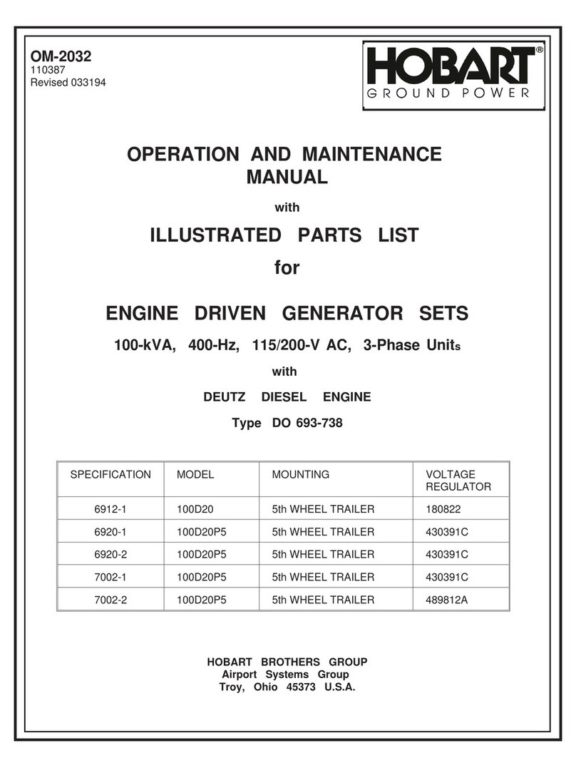
OPERATION AND MAINTENANCE MANUAL
with
ILLUSTRATED PARTS LIST
for
HOBART 400 HZ AC GENERATOR
Synchronous Motor Driven
with
Static Voltages Regulator
Manufactured by
MOTOR GENERATOR DIVISION
HOBART BROTHERS COMPANY I
TROY, OHIO 45373
r
SAFETY INSTRUCTIONS AND WARNINGS FOR ELECTRICAL POWER EQUIPMENT
ELECTRIC SHOCK can kill. Do not touch live electrical parts.
FUMES AftID GASES can be fire and health hazards. Ventilate all fumes and exhaust gasesto the outside.
ELECTRIC ARC FLASH can injure eyes, burn skin, cause equipment damage, and ignite combustible material. Do not
use power cables to break load and be sure tools don’t cause short circuits.
IMPROPER PHASE CONNECTION, PARALLELING, OR USE can damage this and attached equipment.
MOVING PARTS can cause serious injury. Keep clear of moving parts.
IMPORTANT - Protect yourself and others. Read and understand all the instructions in this Operating/Instruction
Manual before installing, operating, or servicing this equipment. Keep this manual available for future
use by all operators.
A. GENERAL
Equipment that supplies electrical power can cause serious injury or death, or damage to other equipment or
property, if the operator does not strictly observe all safety rules and take precautionary actions. Safe practices
have developed from past experience in the use of power source equipment. Certain of the practices below apply to
engine driven equipment.
B. SHOCK PREVENTION
Bare conductors, or terminals in the output circuit, or ungrounded, electrically-live equipment can fatally shock a
person. Have a competent electrician verify that the equipment is adequately grounded and learn what terminals
and parts are electrically HOT. Use proper safety clothing, procedures, and test equipment.
The electrical resistance of the body is decreased when wet, thus more easily permitting dangerous currents to flow
through it. When inspecting or servicing equipment, do not work in damp areas without being extremely careful.
Stand on dry rubber mat or dry wood, use insulating gloves that are effective when dampness or sweat cannot be
avoided. Keep your clothing dry and never work alone.
1. Installation and Grounding of Electrically Powered Equipment - Electrical equipment must be installed
and maintained in accordance with the National Electrical Code, ANSI/NFPA 70, and other applicable codes.
A power disconnect switch or circuit breaker must be located at the equipment. Check the nameplate for voltage,
frequency, and phase requirements. If only 3-phase power is available, connect any single-phase rated equipment to
only two wires of the 3-phase line. DO NOT CONNECT the equipment grounding conductor (lead) to the third live
wire of the 3-phase line, as this makes the equipment frame electrically HOT, which can cause a fatal shock.
---- --- ---
Be sure to connect the grounding lead, if supplied in a power line cable, to the grounded switch box or building
ground. If not provided, use a separate grounding lead. Be certain that the current (amperage) capacity of the
grounding lead will be adequate for the worst fault current situation. Refer to the National Electrical Code ANSI/
NFPA 70 for details. Do not remove plug ground prongs. Use correct mating receptacles.
2. Output Cables and Terminals - Inspect cables often for damage to the insulation and the connectors. Replace
or repair cracked or worn cables immediately. Do not overload cables. Do not touch output terminal while equip-
ment is energized. I
Instruction 910082
Nov 16182 Revised Page 1
C. FIRE AND EXPLOSION PREVENTION
Fire and explosion are caused by electrical short circuits, combustible material near engine exhaust piping, misuse
of batteries and fuel, or unsafe operating or fueling conditions.
1. Electrical Short Circuits and Overloads - Overloaded or shorted equipment can become hot enough to cause
fires either by self destruction or causing nearby combustibles to ignite. Provide primary input protection to re-
move short circuited or heavily overloaded equipment from the line.
2. Battery - Batteries may explode and/or give off flammable hydrogen gas. The acid and arcing from a ruptured
battery can cause fires and additional failures. When servicing, do not smoke, causing sparking, or use open flame
near the battery.
3. Encrine Fuel - Use only approved fuel container or fueling system. Fires and explosions can occur if the fuel
tank is not grounded prior to and during fuel transfer. Shut unit DOWN before removing fuel tank cap. Do not
completely fill tank. Heat from the equipment may cause fuel expansion overflow. Remove all spilled fuel im-
mediately including any that penetrates the unit. After cleanup, open equipment doors and blow fumes away with
compressed air.
D.
E.
F.
TOXIC FUME PREVENTION
Carbon Monoxide - Engine exhaust fumes can kill and cause health problems. Pipe or vent the exhaust fumes to a
suitable exhaust duct or outdoors. Never locate engine exhausts near intake ducts or air conditioners.
BODILY INJURY PREVENTION
Serious injury can result from contact with fans, belts, and pulleys inside the equipment. Shut DOWN equipment
for inspection and routine maintenance. When equipment is in operation use extreme care in doing necessary
troubleshooting and adjustment.
MEDICAL AND FIRST AID TRFATMFNT
First aid facilities and a qualified first aid person should be available for each shift for immediate treatment of all
injury victims. Electric shock victims should be checked by a physician and taken to a hospital immediately if any
abnormal signsare observed.
Call physician immediately. Seek additional assistance and use First Aid techniques recommended
by American Red Cross until medical help arrives.
IF BREATHING IS DIFFICULT, give oxygen, if available, and have victim lie down. FOR ELEC-
TRICAL SHOCK, turn off power. Remove victim; if not breathing, begin artificial respiration,
preferably mouth-to-mouth. If no detectable pulse, begin external heart massage. Call Emergency
Rescue Squad immediately.
G. EQUIPMENT PRECAUTIONARY LABELS
Inspect all precautionary labels on the equipment monthly. Order and replace all labels that cannot be easily read.
I
1 1
3. Service and Maintenance - This equipment must be maintained in good electrical and mechanical condition
to avoid hazards stemming from disrepair. Report any equipment defect or safety hazard to your supervisor and
discontinue use of the equipment until its safety has been assured. Repairs should be made by qualified personnel
only. Shut OFF all power at the disconnecting switch or line breaker before inspecting or servicing the equipment.
Lock switch OPEN (or remove line fuses) so that power cannot be turned ON accidentally. Disconnect power to
equipment i
I’ .
rt ISout of service. If troubleshooting must be done with the unit energized, have present another per-
son trained in turning off the equipment and providing or calling for first aid.
EMERGENCY FIRST AID
Page 2 Instruction 910082
Revised Nov 16182
FORART
B $MOTOR GENERATOR DIVISION
a
“c QD ! HOBART BROTHERS COMPANY
% z
Q. .q,+
TABLE OF CONTENTS
SUBJECT CHAPTER/SECTION PAGE
Introduction
Description/Operation
Description
General
Identification
Standard Unit and Variations
Canopy
Motor
Generator
Hobart Static Regulator
Data
Performance
Dimensions
Control Box Assembly
General
Controls and Instruments
Interior Pane I Assembly
General
Controls and Instruments
Motor Switch Box Assembly
Genera I
Components
1-O
l-1
I
Feb 6/‘74 Contents
Page 1
FOBART
I
QD
;MOTOR GENERATOR DIVISION
z : HOBART BROTHERS COMPANY
“0 2
B . B,,d-
TABLE OF CONTENTS (CONT’D)
SUBJECT
Power Module Assembly
General
Components
Preparation for Use
Genera I
Wiring
Motor Switch Overload Coils
Mounting Installation of Synchronous Motor-Driven
Generator Sets
Operation
Genera I
Remote Control
Variations
Servicing
Maintenance, Inspection/Check
Genera I
Inspection, Testing and Repair
Trouble Shooting
Trouble Shooting Procedures
General
Trouble Shooting Chart
Equipment for Trouble Shooting
Contents
Page 2
CHAPlER/SECTI,ON
l-l
l-2
l-3
2-o
2-l
3-O
3-l
PAGE
12
12
12
1
1
1
1
2
1
1
2
2
1
1
1
1
1
1
1
1
1
SUBJECT CHA PTER/SECT ION PAGE
FOBART
8
5 ;MOTOR GENERATOR DIVISION
3 QD 3 HOBART BROTHERS COMPANY
% 4. 8ud
TABLE OF CONTENTS (CONT’D.)
Safety
’ Diagrams
Connections and Wiring
Chart
II lustrated Parts List
Introduction
Genera I
Purpose
Arrangement
Explanation of Parts List
Manufacturer ‘s Codes
Explanation of Manufacturer’s (Vendor) Code List
Parts List
Explanation of Parts List Arrangement
Symbols and Abbreviations
Feb 6/;74
May 12/75 Revised
3-l
4-o
4-l
4-2
4-3
1
2
2
3 thru 8
1
1
1
1
1
1
1
I
Contents
Page 3
Con tents
Page 4
GENERATOR DIVISION
HOBART BROTHERS COMPANY
Fe b 6/74
HOBART
z
J
QD
$MOTOR GENERATOR DIVISION
:
z HOBART BROTHERS COMPANY
“0
b. B,,\6
INTRODUCTION
This manual contains operation and service information and instructions for Hobart 400-Hz
Ground Power Generating hit, driven by a synchronous motor. Specification numbers
and model numbers for each model covered by this manual are listed below. See Data,
sub-seption 8, page 2, this Section, for complete details on various units.
Specs. 4576A (S-4576A) Mode I 32 1O-50
Specs. 4713A (S-4713A) Model 3210
Specs. 4820A (S-4820A) Mode I 3209-50
Specs. 4910B (S-4910B) Model 3209
In addition to the standard unit,, the manual also covers variations to the basic specifications,
which are designated by a numerical suffix to the specification number, on the nameplate.
A sub-section entitled “Variations” in Chapter 1 explains these variations, and will include
any such new variations as they are added in the future.*
The manual is in no way presented as a text book on electricity or electronics. Its primary
purpose is to provide information and instructions to experienced operators, electricians
and mechanics who have never seen nor operated this particular generator set. It is the
intent of the manual to guide and assist operators and maintenance personnel in the proper
use and care of the equipment.
Use of the manual should not be put off until a trouble or need for help develops. Read the
instructions before starting the unit. Learn to use the manual and to locate information con-
tained in it. Each page is identified in the lower outside corner by the chapter and section
number in which it appears. Each new section starts with page 1. The figure numbers with-
in the’manual are numerically consecutive throughout the manual, regardless of the section
in which they appear.
In addition to operation and maintenance instructions, the manual containsan Illustrated
Parts List in Chapter 4. A collection of manufacturer’s I iterature is supplied as part of the
information package;
* From time-to-time, specialized use of this equipment may require the addition of
other appropriate instructions and parts lists (VARIATIONS) to the basic manual.
Individual pages that specifically describe ‘the variation are inserted at the front of this
manual as ADDENDUM SHEETS.
I
Introduction
Page 1