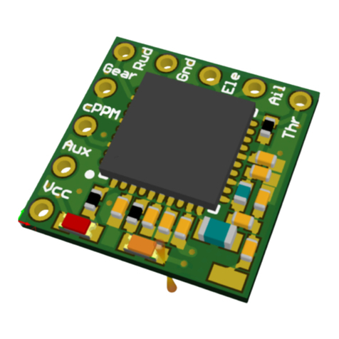
Hobby King OrangeRX George 4 User manual

Page 1 of 9
O
RANGE
RX
G
EORGE
4
S
ERVO
R
ECEIVER WITH
S
TABILIZER AND
ESC
U
SER MANUAL
FCC
ID:
2AOCYGEORGE
P
RODUCT OVERVIEW
:
D
ESCRIPTION AND FEATURES
:
The device combines 4 devices in one, compact format
1. 12 channel DSM2/DSMx compatible receiver
2. 3 axes stabilizer working with various planes configurations and having 3 different types of stabilizing behavior.
3. 6A continuous 10 peak brushless ESC
4. 1.5A 5V switching BEC for servos.
5. Working voltage is 7.4~12.6VDC (2s or 3s batteries)
R
ECEIVER
:
• Diversity antennas for perfect reception and telemetry of micro models (500m LOS)
• Integrated telemetry for real time readings:
- Battery voltage
- Receiver voltage
- Lost packets (signal quality)
Range: 500m LOS (Line Of Site) or more**
Telemetry range – up to 200m. LOS or more**
ESC:
ESC- 6A continuous, 10A peak integrated ESC for BLDC motor. It is already calibrated to work with stabilizer in airplane mode.

Page 2 of 9
DIMENSIONS:
39x28x8 mm
WEIGHT
9.3 grams (including wires and connectors)
CONNECTIONS:
The receiver has following connections:
- Battery connector – connect to your power battery using JST connector.
- 4 1.5mm Molex connectors for servos
S1 – Ailerons
S2 – Elevator
S3 – Rudder
S4 – Gear (can be programmed as second Aileron or Flaps or any other output needed)
- 1 1.5mm Molex connector for PC connection via UART to USB adapter
- 3 leads to connect brushless motor (black thick wires).
BUTTONS:
The receiver has one button which is used for firmware update. (Upd)
LED-S:
The receiver has two LED-s – Red and Blue.
Blue LED indicates receiver functionality
- Binding state – blinks rapidly
- Signal presence state – solid ON
- No signal – LED is OFF
Red LED indicates stabilizer functionality
- After the device is turned ON Red LED is ON indicating that the stabilizer is not ready yet. After receiver and stabilizer are successfully
initialized Red LED will go OFF.
- The device is ARMED – solid ON
- If dangerous angle of the plane is detected (more than 30 degree to the horizon on bank or pan) the LED will start blinking slowly indicating
that it is not safe to start motor. Arming will not be possible in these conditions. You need to bring your plane in the straight upright position to
be able to arm motor,
BINDING:

Page 3 of 9
The receiver will work with any DSMx/DSM2 compatible transmitter or Tx module.
There is two ways to initiate binding procedure:
1. Manual binding by power ON with pins 2 and 3 on UART connector shortened;
2. Autobind - after 30 seconds of no known signal from transmitter received the device will initiate binding procedure. If the receiver didn’t see
any transmitter in binding mode nearby for 30 seconds, the receiver will turn binding mode off for safety reasons.
The receiver indicates binding mode by rapid blinking of blue LED (3-4Hz). Follow the instructions of your transmitter to initiate its binding.
During binding blue LED will change the pattern of binding and if the binding was successful blue LED will become solid ON.
MOUNTING STABILIZER IN THE PLANE:
Mount stabilizer in the plane on flat solid surface parallel to the wings and in line with fuselage, antennas facing front. Place stabilizer close to
the center of gravity of the plane. It will make the stabilizer work better. Use double sided foam supplied with stabilizer or similar. Try to
minimize vibrations of the plane(propeller better to be balanced) because vibrations will affect the stabilizer performance.
STABILIZER:
• 4 channels PWM output to servos
• 3 mode of stabilizer
- Acro Pro mode - rates, no autolevel
- Advanced mode - autolevel mode with acro capability
- Beginner mode – “SAFE” mode, envelope. User can limit the maximum angle of pitch and roll.
• Bypass mode – for experienced pilots and aircraft tuning – no stabilization, direct control of aircraft
• 3 aircraft schemes
- T-Tail (Classical)
- V-Tail -
- Delta (Flying wing)
The stabilizer can be connected to the PC using USB-UART adapter (sold separately)
Settings for UART are 115200, N, 1.
A PC software can be downloaded from “Files” section from the Hobbyking Web site.
Using PC software is similar to most of the flight control PC apps and self-explanatory.
Using PC software you can:
• Tune PID-s for different aircrafts with typical tuning presets and mixes for T-tail, V-Tail, Delta;
• By various servo assignment and mixes set up the aircraft with virtually any servo position and orientation;
• Set various aspects of the stabilizer behavior, assign channels for flight modes and much more.
• Save and restore set ups to keep different configurations for different aircrafts
SETTINGS VIA GUI :
Please note: GUI outlook is for reference only. It will be changed in commercial release.
FIRMWARE UPGRADES:
• Firmware upgrades are done via UART interface and GUI. Pre
Page 4 of 9
SETTINGS VIA PROGRAM CARD (SOLD SEPARATELY :
1. P ge 1 of PID settings.
Click the roller wheel to enter the menu You can chose the axis to change – ROLL, PITCH, YAW . Step on the axis whose
parameters you want to edit. Click Enter again. Now you can navigate between P, I and D parameters. Click enter again.
The edited parameter will start blinking. Use roller to change the value. When value is changed press Enter again and
exit the value changing mode. You can navigate to another parameter and change their values if you need. After
changes are done push roller UP several times to exit to upper and upper levels and finally exit. The window will pop up
asking if you want to save changes. Choose what you want to do and click Enter on the roller. The changes will be
transferred to the flight control to save.
Note: when some parameters are changed but not saved yet, the info string appears: “p r m chng” telling you that
parameters are changed but still not stored in flight control.

Page 5 of 9
2 P ge 2 of PID settings.
Beginner sens – sensitivity for Beginner mode. If sensitivity is too high the model can start oscillating. Lower sensitivity
in this case.
Adv nce sens – sensitivity for Advanced mode. If sensitivity is too high the model can start oscillating. Lower sensitivity
in this case.
Stick p r m – the parameter how far from the center a control stick needs to be to disable autolevel in advanced mode.
The value range is 0…255 from stick in middle to the extreme position. This parameter allows to make rolls and loops in
Advanced mode.
3 P ge 3 Flight setup.
Angle not ARM prevents ESC to arm if the model is tilted beyond set angle to the horizon (in degrees
Angle envelop – limits the maximum angle of bank and tilt in Beginner mode to the horizon (in degrees .
F ilS fe thr – Throttle level in FailSafe situation(signal loss .Acceptable values are 1000us...2000us. Keep it low to stop
the motor in signal loss event(about 1000-1100us .
FS off del y – delay to turn motor off in Fail Safe. In most cases keep it about 1second

Page 6 of 9
4 P ge 4 Servo output settings
Press Enter on dial to enter the menu. If you need to change the servo you want to set, press Enter again and the cursor
will highlight servo name (Ail, Rudd,etc . Press Enter again to exit from the servo selection submenu.
Servo – name of channel, (Ail1, Ail2, Elev, Rudd which will be set;
Min – Lowest servo endpoint (us . Range is 1000us…2000us
Mid – middle position of the servo (us . Changing this parameter you can subtrim servo in middle point.
M x – Highest servo endpoint (us . Range is 1000us…2000us
R te – Rates of the servo output, %. Range is 0%…100%
Dir – servo direction, (Normal, Reversed
5 P ge 5. Assignment Flight Modes to ch nnels.
ARM – Channel to set for ESC arming. If chosen «--» arming will be performed by rudder stick moved left when the
throttle is in lowest position. To disarm the motor with you will need to bring the throttle down and move the rudder
stick right.
Beginner – Channel and its position to activate Beginner mode
Adv nced – Channel and its position to activate Advanced mode
Please note, if Beginner or Advanced modes are not active, then Rates(Pro mode is selected by default. In this mode the
aircraft will be stabilized from wind disturbance but the self-leveling functionality will be disabled.
P ss Thru – If this mode is active the stabilizer is disabled completely, It will pass all the controls from your transmitter
to the aircraft servos. It is a useful mode for experienced pilots to fine tune the aircraft.
Available channels to assign : "AUX1 low", "AUX1 mid", "AUX1 high", "AUX2 low", "AUX2 mid", "AUX2 high", "AUX3 low",
"AUX3 mid", "AUX3 high", "AUX4 low", "AUX4 mid", "AUX4 high", "always ON"
“Always ON” option makes the selected feature always enabled regardless of any channel state.

Page 7 of 9
6 P ge 6.Model type nd throttle settings.
Mdl type – you can chose appropriate type of your model for servo mixing. Available options:
"F-Wing", "Classic", "V-Tail"
Min thr – Minimum throttle for ESC when the throttle stick is low
M x thr – Maximum throttle for ESC when the throttle stick is high
Min comm nd – Minimum throttle for ESC during initial calibration on start.
Ple se note: If the model type is changed, all previous settings will be erased and set to default values. You will need to
set them again according to your needs.
7 P ge 7. Accelerometer c libr tion
To calibrate an accelerometer:
1. Place the plane horizontally in exact position as it is supposed to be during the flight straight. The plane should stay
still and stable in this position. Do it indoor because wind will affect calibration settings.
2. Enter Calibration menu. Confirm to start calibration process.
Please note that during calibration the stabilizer will be disconnected from the Programming Card for short period of
time. Do not touch or move your plane at this moment.
After calibrating is finished, the connection with the Programming Card will be restored and the message «ACC ok» will
appear on the top side of the screen.

Page 8 of 9
8. P ge 8. Ch nnels’ inputs
.
Program Card can act as Transmitter when it works with the stabilizer. In this mode Program Card outputs channel
values to the receiver imitating transmitter. In this mode you can change these values as if you would do this using. You
can set values on the each servo output. This is very useful for mechanical setup of planes for example.
9. P ge 9. Device info.
*Note:
1) This is not a Spektrum DSM2/X product, nor is it a copy of a Spektrum DSM2/X product.
The Spektrum and DSM2/X brand is a trademark of Hori on Hobbies USA.
2) This is not an underground black market fake Spektrum product. OrangeRx quality is guaranteed.
3) Accepted by the MAAA in Australia, see the MAAA MOP58 for guidance
FCC Statement
Caution: The user is cautioned that changes or modifications not expressly approved by the party responsible for compliance could void
the user's authority to operate the equipment.
Note: This equipment has been tested and found to comply with the limits for a Class B digital device, pursuant to part 15 of the FCC
Rules. These limits are designed to provide reasonable protection against harmful interference in a residential installation. This
equipment generates, uses and can radiate radio frequency energy and, if not installed and used in accordance with the instructions,
may cause harmful interference to radio communications. However, there is no guarantee that interference will not occur in a particular

Page 9 of 9
installation. If this equipment does cause harmful interference to radio or television reception, which can be determined by turning the
equipment off and on, the user is encouraged to try to correct the interference by one or more of the following measures:
—Reorient or relocate the receiving antenna.
—Increase the separation between the equipment and receiver.
—Connect the equipment into an outlet on a circuit different from that to which the receiver is connected.
—Consult the dealer or an experienced radio/TV technician for help.
Table of contents
Other Hobby King Receiver manuals

Hobby King
Hobby King OrangeRx R910 User manual

Hobby King
Hobby King D58-4 User manual

Hobby King
Hobby King orange r410x User manual

Hobby King
Hobby King ORANGE R616XN User manual

Hobby King
Hobby King ORX TX10i User manual

Hobby King
Hobby King ORANGE R618XL User manual

Hobby King
Hobby King ORANGERX R614XN User manual

Hobby King
Hobby King ORANGE R1220 Series User manual

Hobby King
Hobby King ORANGE R620 Series User manual

Hobby King
Hobby King ORANGE R415X User manual