Hobby King Turnigy V-Bar 600 User manual

1
Turnigy® V-Bar 600
Flybarless System V2.0
Preface
The Turnigy® V-Bar 600 is an extremely high quality precise controller and stabilizer for the swashplate and
tail rotor of a model helicopter flight control system. It has super-stabilization and super-response to control
input. This makes for incredible stability and agility. The programmability allows for performance settings
from smooth scale to sport or hard 3D flying. Flybarless also means longer flight times and a tremendous
reduction of parts and aerodynamic drag. You no longer need to use an external tail gyro, resulting in
reduced weight, with a large cost savings. The Turnigy® V-Bar 600 offers 4 switchable flight modes.
Technical details:
●MEMS Gyro Sensors in three axes
●Digital signal processor
●Operating voltage: 4-10 Volts, current < 80mA
●Temperature range: -10°C to +50°C
●Size: 33x34x18 mm
●Weight: 15 g
●Servo compatibility: 1520uS/333Hz, 1520uS/250Hz, 1520uS/167Hz
and 760uS/333Hz digital servos, 1520uS/71Hz Analog servo.
●Spare parts: foam and double-side adhesive tape and Stainless steel plate.
Installation
:
Please only use a thick double sided adhesive pad when installing the
Turnigy® V-Bar 600 to an electric helicopter. If installing on a nitro or
turbine
helicopter, you may want to use 2 double sided adhesive pads on the
bottom, plus a stainless plate on the top, plus a thin double sided
adhesive pad on the top layer for better vibration isolation.
As shown in the pictures below,
When installing Turnigy® V-Bar 600 to helicopter you can choose the
following four directions. If the Turnigy® V-Bar 600 is installed on bottom of the helicopter, the same four
directions can be chosen as well.
Turnigy® V-Bar 600 runs parallel to the helicopter (nose):

2
Turnigy® V-Bar 600 runs perpendicular to the helicopter (nose):
The distance between the blade grip ball link and the center of the helicopter rotor head should be
no less than 25mm for rotor diameter of 1.15m. As rotor diameter increases, adjust this value
accordingly. Too small of an offset will result in improper resolution for optimal performance.
Turnigy® V-Bar 600 port connection definition:
Instructions:

3
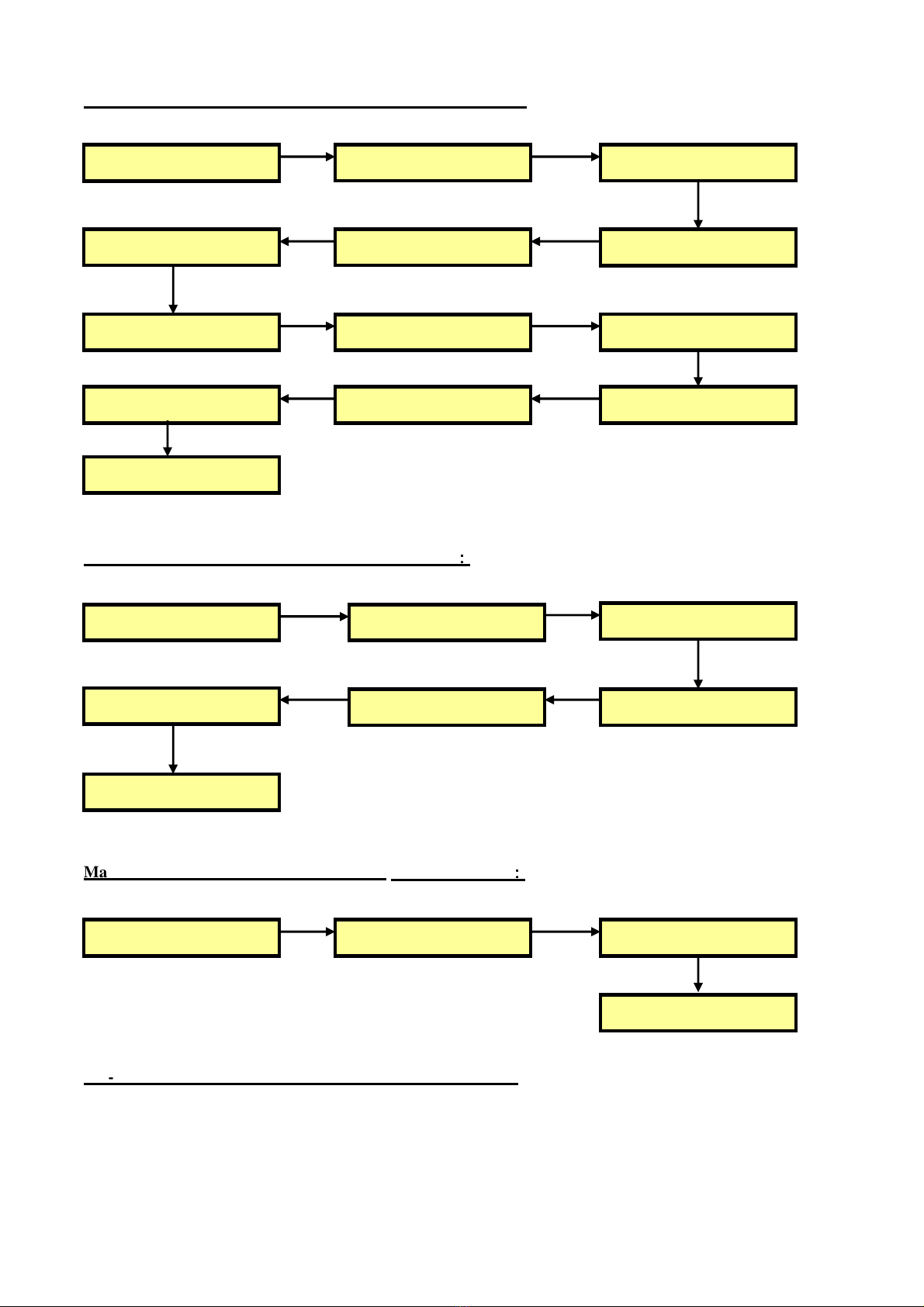
Please perform the following steps, to install the Turnigy® V-Bar 600.
●A rigid rotor head has no flybar, no washout assembly and no pitch mixer arms.
You must have a flybarless head with proper geometry installed
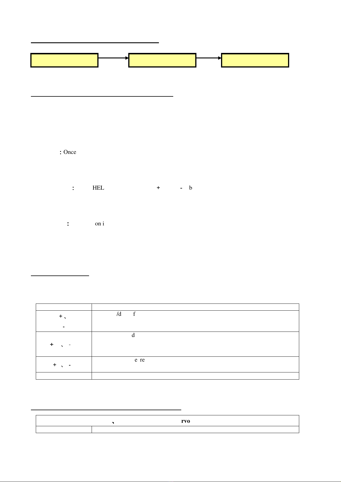
●Install Turnigy® V-Bar 600 correctly as illustrated above.
●Connect Turnigy® V-Bar 600 to receiver. Don not connect the servos to the Turnigy® V-Bar 600 at this
time.
●Ensure that the transmitter trims and sub-trims are set to zero, and that collective pitch to tail pitch mixing
is disabled.
●Ensure the swashplate type of transmitter is H1.
●Adjust the rudder, pitch, aileron and elevator servo travel (ATV, end point) to +/-100% in your transmitter.
●Set a gain switch in your transmitter for switching flight mode.
●Refer to the following LCD Setting Adaptor guide for detailed setting .
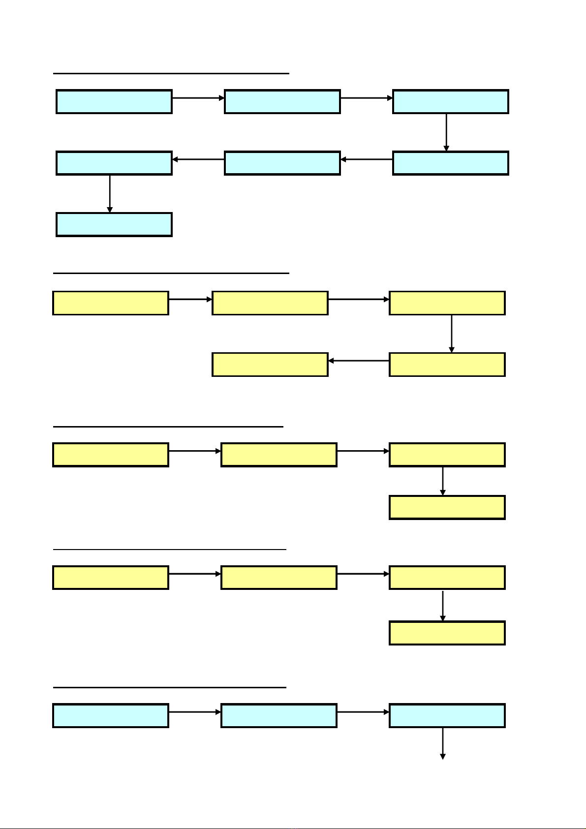
●Connect the servos(rudder,aileron, elevation,pitch) to Turnigy® V-Bar 600.
●Set the gain in your transmitter so that the Turnigy® V-Bar 600 is in memory bank 0, see page 5 before
continuing
●Set tail gyro gain in Turnigy® V-Bar 600 to be in normal mode (heading hold off).
●Select “READ DATA” menu and read the data under the flight mode
●If you switched gain switch, you must select “READ DATA” menu and read the data under the flight
mode.
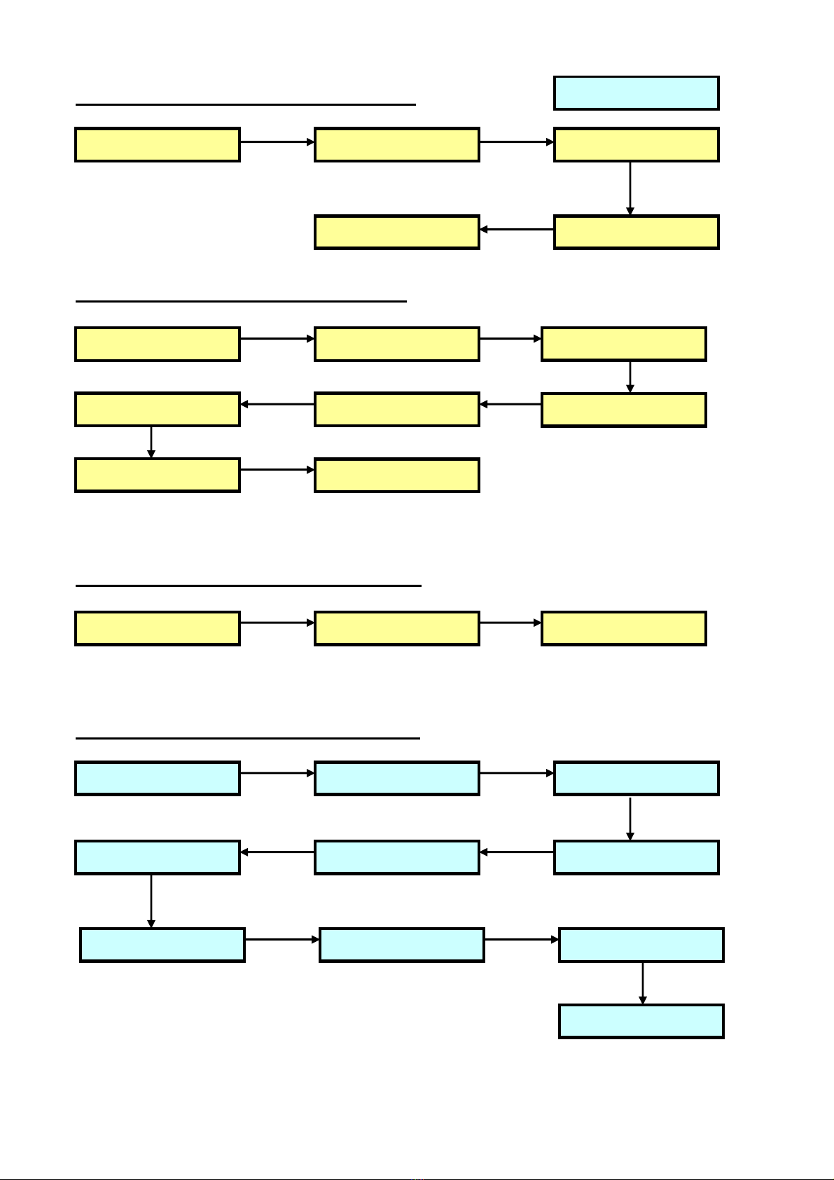
●Rudder servo is in normal mode. Perform mechanical adjustment of the rudder servo horn and control
linkages to achieve approximately 8deg tail pitch.
●Confirm correct relationship of rudder stick and Turnigy® V-Bar 600 response to tail movement. Confirm
there is no mechanical binding.
●Confirm correct relationship of aileron stick and Turnigy® V-Bar 600 response to swashplate movement.
Confirm there is no mechanical binding.
●Confirm correct relationship of elevation stick and Turnigy® V-Bar 600 response to swashplate
movement. Confirm there is no mechanical binding .
●Confirm correct relationship of pitch stick and Turnigy® V-Bar 600 response to swashplate movement.
Confirm there is no mechanical binding.
In order to determine Turnigy® V-Bar 600’s Neutral Point, please don’t move the helicopter for
3 seconds
after powering on. Bind Turnigy® V-Bar 600 tightly with Velcro, avoiding that the helicopter body is
vibrated to cause Turnigy® V-Bar 600's shake.
Power up Turnigy® V-Bar 600, and connect with LCD programmer.
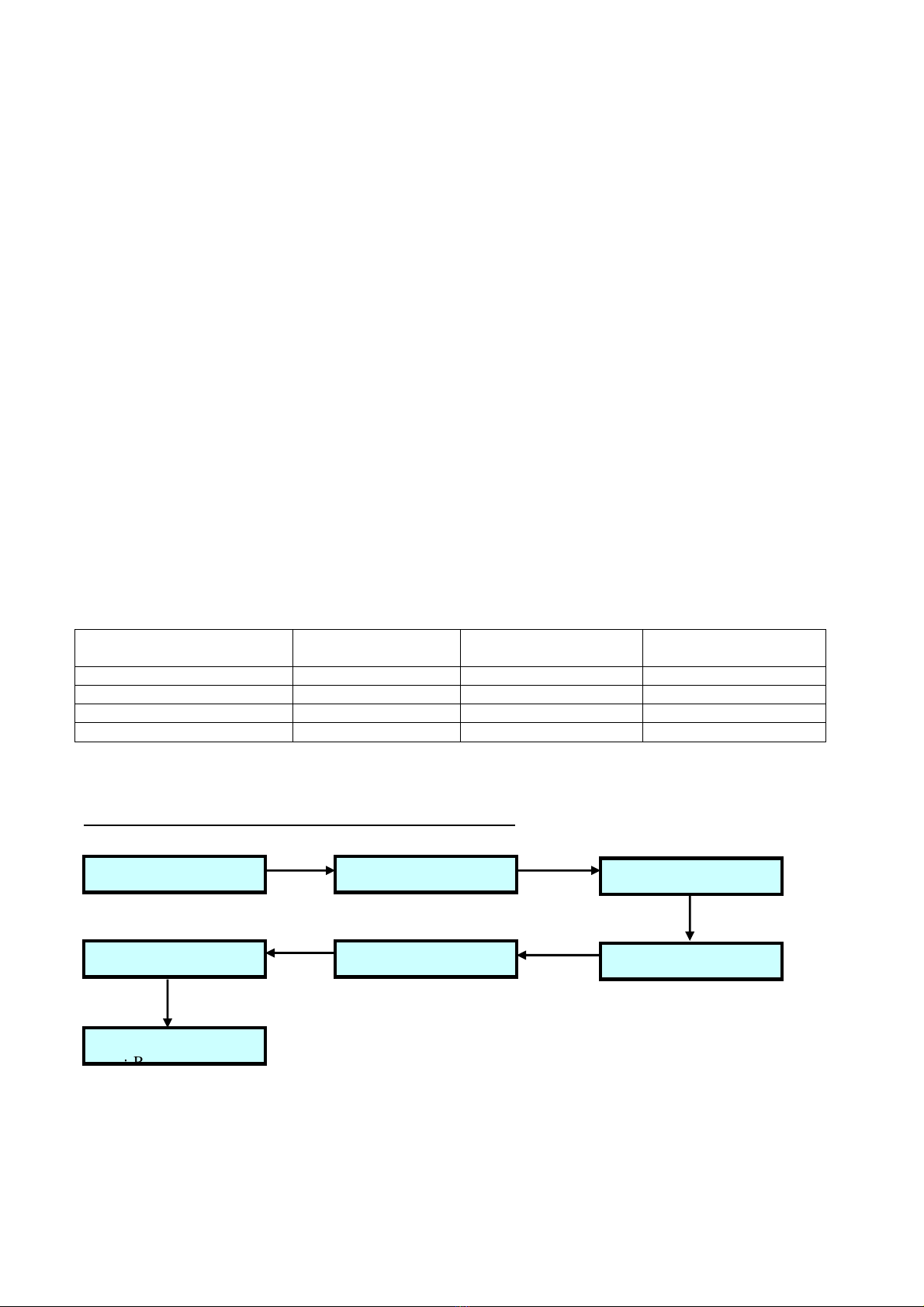
Status LED:
During normal operation the LED provides simple status information for users.
On
:
AVCS and Normal mode. Rudder stick at neutral.
Short blink two times:
Rudder input detected.
Off
:
Lose of gain signal .
repeating flash:
Error. Gyro not receiving valid signal from the receiver or unable to calibrate
because the rudder stick is not centred.
LCD Setting:

4
Turnigy® V-Bar 600 Main Menu Configuration Steps:
::
:
Main Menu Configuration Steps Without flight mode
:
::
:
Main Menu Configuration Steps Associated With flight mode
:
::
:
GN-MODE displays current gain pulse width and flight mode:
The Turnigy® V-Bar 600 is capable of flying with four switchable flight modes which are pilot
selected from the transmitter. This is the same process as selecting the gain in your tail gyro but it can
configure all the flight characteristics on three axis’s. If you only plan on using one flight mode it is
advisable to leave the gain wire off of the installation and move on to setup.
9: TAIL GAIN MISC
2: TAIL BASE PARAM
12: PIRO OPTIMIZE 11: SWPL GAIN FEEDBK
4: SWPL MIXER RATE
7: SWPL SERVOS TRIM
10: TAIL TORQUR COMP
8: SENS DIRECT DEAD
6: SWPL HIGH POINT 5: SWPL LOW POINT
1: GN-MODE 3: SWPL-TYP SRV-DIR
2: TAIL BASE PARAM 4: SWPL MIXER RATE
7: SWPL SERVOS TRIM
8: SENS DIRECT DEAD
6: SWPL HIGH POINT 5: SWPL LOW POINT
3: SWPL-TYP SRV-DIR
9: TAIL GAIN MISC 11: SWPL GAIN FEEDBK10: TAIL TORQUR COMP
13: READ DATA
12: PIRO OPTIMIZE

5
When setting up the Turnigy® V-Bar 600 you use the transmitter to select which flight mode is being
programmed. If you have the gain channel connected the pulse width on the gain channel controls which
flight mode the Turnigy® V-Bar 600 is in and which flight mode is being programmed. Simply switching to
the desired flight mode will tell the Turnigy® V-Bar 600 to change values for the selected mode. If the gain
channel is not connected you will program Flight Mode 0. If you do not intend on using multiple flight
modes it is best to not connect the gain channel.
Pulse width is used by Radio Control systems to communicate between the radio and receiver the channel
value information. This information corresponds to desired servo positions, gain value etc. The pulse width
different radio systems such as FUTABA or JR varies to some extent but is approximately 1-2
milliseconds.Below is a table of the pulse width ranges acceptable to select each flight mode.The program
box can read the pulse width on the gain channel to verify the flight mode you are in and that your radio is
setup properly. Please consult your radio manual for instruction on how to setup multiple flight modes. A
pulse width of approximately 1500 microseconds corresponds to center stick/center servo position. Flight
modes with the Turnigy® V-Bar 600 are set with pulse widths from 1620 to 1919 microseconds.
The values below are only examples. In some cases the radio range may be 0-100 in others +/- 100%.
You should always check the actual pulse width is correct to get each mode setting by reading the Turnigy®
V-Bar 600 data after the radio is switched to the desired mode
Display Format: gggg-m. gggg is 4-digit gain pulse width in us. m is 1-digit flight mode. If switching
gain switch, the flight mode shall be changed. Before configuration Turnigy® V-Bar 600, select “READ
DATA” menu and press any button of +/-10 and +/-1 to read the data under the flight mode. Turnigy® V-Bar
600 can save the data under four flight modes. The flight modes corresponding to gain pulse widths are as
follows:
Gain Pulse Width in (us)
Flight Mode
Futaba 10CH
X Gain %
Gyro Sense AVCS Mode
JR 9303 Gain % For
Auto Gyro Sense
Gain<1620 or Gain>1920
0
0
-
23
0
-
64
Between 1621 and 1719
1
35
71
Between 1721 and 1819
2
58
84
Between 1821 and 1919
3
81
96
TAIL BASE PARAM Submenu Configuration Steps:
::
:
1: TAIL-SRV 2: RUD-DIRE
4: RUD-LEND
5: RUD-HEND
6: RUD-DEAD
7
:
RETURN
3: RUD-TRIM

6
SWPL-TYP SRV-DIR Submenu Configuration Steps:
SWPL MIXER RATE Submenu Configuration Steps:
SWPL LOW POINT Submenu Configuration Steps:
SWPL HIGH POINT Submenu Configuration Steps:
SWPL SERVOTRIM Submenu Configuration Steps:
1: GYRO-POS 2: SWPL-TYP 3: SWPL-SRV
4: AIL-DIRE5: ELE-DIRE6: PIT-DIRE
7: RETURN
2: ELEV-RAT 3: PITC-RAT
4: CYCL-LMT5: RETURN
1: AILE-RAT
1: AIL-LEND 2: ELE-LEND 3: PIT-LEND
4: RETURN
1: AIL-HEND 2: ELE-HEND 3: PIT-HEND
4: RETURN
1: AIL-TRIM 2: ELE-TRIM 3: PIT-TRIM

7
SENS DIRECT DEAD Submenu Configuration Steps:
TAIL MISC PARAM Submenu Configuration Steps:
TAIL TORQUE COMP Submenu Configuration Steps:
SWPL GAIN FEEDBK Submenu Configuration Steps:
4: RETURN
1: AIGY-DIR 2: ELGY-DIR 3: AIL-DEAD
4: ELE-DEAD5: RETURN
2: RUDLSTOP 3: RUDRSTOP
4: RUDD-ACC5: RUDD-DEC6: RUD-EXP
1: TAILGAIN
8: RETURN7: RUD-SENS
3: RETURN
1: PIT-COMP 2: CYC-COMP
1: AIL-GAIN 2: ELE-GAIN 3: AIL-FEED
4: ELE-FEED
5: AILLSTOP6: AILRSTOP
7: ELELSTOP 8: ELERSTOP 9: V-SWPLRO
10: RETURN

8
PIRO OPTIMIZE Submenu Configuration Steps:
READ DATA reads the data under current flight mode:
If the gain, stop gain, feedback factor and the compensation of torque change to tail servo is required to set
after switching into different flight mode, select this menu and press any button of +/-10 and +/-1 to read the
data under the flight mode.
Power On
:
::
:
Once power on, LCD will display HELLO. After 5 seconds, configuration card will display
Turnigy® V-Bar 600 settings and is ready for use.
Default Setting
:
::
:
When HELLO is display, press
+
10 and
-
1 buttons simultaneously. Configuration will
return to default value.
System Reset
:
::
:
Reset button is located at the bottom of LCD configuration card.
Return to the previous menu: Press FUNC+ or FUNC- buttons, select “return” menu when Scroll up/down
function menu. Press any button of +10 ,-10,+1,-1, return to the previous menu.
Button Description:
Total 7 function keys: FUNC+, FUNC-, +10, -10, +1, -1, Reset
Description
Function
FUNC
+、
FUNC
-
Scroll up/down function menu
+
10
、-
10
Increase (+) or decrease (
-
) value by 10 units each time.
Automatically change to 1 units if the maximum function value is less than 20.
Enter for main menu and “RETURN”
+
1
、-
1
Increase (+) or decrease (
-
) value by 1 unit each time.
Enter for main menu and “RETURN”
Reset
System reset
TAIL BASE PARAM Su
bmenu Configuration Steps:
::
:
1
、
、、
、
TAIL-SRV ---- rudder servo type selection
Menu Items
Descriptio
n
3: RETURN
1: PIRO-THR 2: PIRO-OPT

9
152-33
(
Default
)
Servo pulse width 1520us, working frequency 333Hz includes
:
Futaba
:
S9253
、
S9254
、
S9650
、
S9257
、
S3153
JR
:
8900G
、
DS3405
、
DS3500
Hitec
:
HS-5084MG
、
HS-5925MG
LogicTech
:
3100G
If the servos work in abnormal state, it doesn't adapt to 333 Hz frequency, select
the option with lower frequency of 152-25 (1520us/250Hz) or 152-07
(1520us/71Hz).
76-33
Servo pulse width 760us, working frequency 333Hz includes
:
Futaba
:
S9251
、
S9256
、
BLS251
LogicTech
:
6100G
152-25
Servo pulse width 1520us, working frequency 250Hz includes
:
Futaba
:
S3154
JR
:
8700G
、
2700G
Align
:
DS510
、
DS520
、
DS620
152-167
Servo pulse width 1520us, working frequency 167Hz includes
:
Align
:
DS410
、
DS610
Low-speed digital servo.
152-07 Servo pulse width 1520us, working frequency 71Hz includes
:
analog servo, low-speed digital servo.
Suggestion
High
-
frequency digital servo is compatible to low
-
frequency pulse. If you did not
know which kind of frequency the 1520us digital servo adapts. Choose 152-11
(1520us/111Hz) for trial firstly, if the heli is not works, choose 152-07
(1520us/71Hz) to analog the servo specification. If it works normally, rechoose
152-25 (1520us/250Hz) or 152-33 (1520us/333Hz) for trial. The frequency chosen
is higher, the flight effect is better.
2
、
、、
、
RUD-DIRE----- Rudder gyro direction selection

1
0
A
ttention
: Check that the rudder direction matches the transmitter stick direction. Otherwise, please
reverse the rubber direction in transmitter program.
Menu items
Description
NORM
(Default)
Rotate the helicopter left (nose). Rudder servo should compensate to the right
automatically. Otherwise, change value to “REV”. As shown in the diagram.
REV
Rotate the helicopter left (nose). Rudder servo should compensate to the right
automatically. Otherwise, change value to “NORM”. As shown in the diagram.
3
、
、、
、
MID-TRIM---- Rudder Servo Neutral Adjustment
Attention:
Rudder SUB TRIM value of Transmitter should be set to zero . Install rudder servo horn to
closest to 90 degree. Use MID-TRIM to fine tune the neutral point of servo horn to achieve exact 90 degree.
Check the neutral position by switching the Turnigy® V-Bar 600 to the NOR mode, or by moving the rudder
stick to the left and right at least three times at high speed and immediately returning the stick to the neutral
position. This temporarily resets the rudder servo.
Menu items
Description
-
100 ~
0
~ +100
(
Default 0
)
Fine tune rudder servo neutral point.
4
、
、、
、
RUD-HEND----- Rudder High Travel Limit
Menu items
Description
130~ 240
(Default 160) Adjust rudder servo travel at end limit.
Suggestion
Suggested setting between 160
~
230. If setting is higher than 230, please install ball
link to the outer hole of servo horn or use longer horns. If setting is lower than 140,
please install ball link to the inner hole of servo horn or use shorter horns. It is
recommended to keep difference between RUD-HEND and RUD-LEND within ±20.
5
、
、、
、
RUD-LEND ----- Rudder Low Travel Limit
Menu items
Description
130 ~ 240
(Default 160) Adjust rudder servo travel at end limit.
Suggestion
Suggested setting between 160
~
230. If setting is higher than 230, please install ball
link to the outer hole of servo horn or use longer horns. If setting is lower than 140,
please install ball link to the inner hole of servo horn or use shorter horns. It is
recommended to keep difference between RUD-HEND and RUD-LEND within ±20.
6
、
、、
、
RUD-DEAD ------ Rudder Stick Dead Zone
Menu items
Description
5
~
100
(Default 6)
Rudder has no response if stick movement in deadband zone.Useful to prevent minor
unintentional rudder stick commands.
Suggestion
Rudder stick at neutral point.If led continue Short blink 2 times, indicating that the
Turnigy® V-Bar 600 is received rudder signal form receiver. The rudder stick is not
Direction of resulting yaw.
Direction of resulting yaw
Tail rotor
thrust
Tail rotor
thrust

11
in
deadband zone.Increase RUD
-
DEAD.
SWPL-TYP SRV-DIR Submenu Configuration Steps:
1. GYRO
-
POS
-----
Turnigy® V
-
Bar 600 Placement Selection
Item
Content
NORM
(Default)
Turnigy® V
-
Bar 600 runs parallel to the helicopter (nose) and can be placed at the
top and the bottom. It shall be powered on when changing the placement.
ROT-90
Turnigy® V
-
Bar 600 runs perpendicular to the helicopter (nose) and can be placed
at the top and the bottom. It shall be powered on when changing the placement.
2
、
、、
、
SWPL-TYPE -----Swashplate Type Selection
Item
Content
120DEG
(Default)
Transmitter
should be in H1 model. Turnigy® V
-
Bar 600 controls 3 swashplate
servos after being mixed controlled by Turnigy® V-Bar 600 using 3-point (120°)
link method.
135DEG
Transmitter
should be
in H1 model. Turnigy® V
-
Bar 600 controls 3 swashplate
servos after being mixed controlled by Turnigy® V-Bar 600 using 3-point
(135°/140°) link method.

1
2
NORLNK
Transmitter
should not be in H1 model. Aileron,elevator and pitch from receiver directly
controls 3 swashplate servos without being mixed controlled by Turnigy® V-Bar 600 using 3-
point (120°/135°/140°) method.
3
、
、、
、
SWPL-SRV -----Swashplate Servos Category Selection
Item
Content
152
-
07
(Default)
Servo
s
pulse width 1520us, working frequency
71
Hz incl
udes
:
analog servo, low-speed digital servo.
152-33
Servo
s
pulse width 1520us, working frequency 333Hz includes
:
Futaba
:
Futaba: S9253, S9254, S9650, S9257
JR: 8900G, DS3405, DS3500
Hitec: HS-5084MG
、
HS-5925MG
LogicTech: 3100G
76-33
Servos pulse width 1520us, working frequency 333Hz includes
:
Futaba
:
S9251
、
S9256
、
BLS251
LogicTech
:
6100G
152-25
Servos pulse width 1520us, working frequency 250Hz includes
:
Futaba
:
S3153
JR
:
8700G
、
2700G
Align
:
DS510
、
DS520
、
DS620
Ino-Lab
:
202
152
~
167
Servos pulse width 1520us, working frequency 167Hz includes
:
Align
:
DS410
、
DS610
Low-speed digital servo.
Suggestion
High
-
frequency digital servo is compatible to low
-
frequency pulse. If you did not
know which kind of frequency the 1520us digital servo adapts. Choose 152-16
(1520us/167Hz) for trial firstly. If the body oscillates, please reduce elevation and
aileron gain. If the oscillation of body still can not be solved, choose 152-07
(1520us/71Hz) to analog the servo specification. If it works normally, rechoose

1
3
152
-
25 (1520us/250Hz) or
152
-
33 (1520us/333Hz) for trial. The frequency chosen
is higher, the flight effect is better.
4
、
、、
、
AIL-DIRE-----Aileron Servo Direction Selection
Item
Content
NORM
(Default)
Move the collective pitch stick forward, while the aileron servo should be moved
upward,
if not, please adjust the data to
「
REV
」
.
REV
Move the collective pitch stick forward, while the aileron servo should be moved upward,
if not, please adjust the data to
「
NORM
」
.
Suggestion
Notice: verify the correct direction of aileron is right
when aileron stick turning to right.
Otherwise, please turn back the “Aileron” item of “Reverse” function in the transmitter.
5
、
、、
、
ELE-DIRE-----Elevator Servo Direction Selection
Item
Content
NORM
(Default)
Move the collective pitch stick forward, while t
he elevator servo should be moved upward,
if not, please adjust the data to
「
REV
」
.
REV
Move the collective pitch stick forward, while the elevator servo should be moved upward,
if not, please adjust the data to
「
NORM
」
.
Suggestion
Notice: verify the corr
ect direction of elevation is upward when elevation stick moving
forward. Otherwise, please turn back the “Elevator” item of “Reverse” function in the
transmitter.
6
、
、、
、
PIT-DIRE-----Pitch Servo Direction Selection
Item
Content
NORM
(Default)
Move the coll
ective pitch stick forward, while the pitch servo should be moved upward, if
not, please adjust the data to
「
REV
」
.
REV
Move the collective pitch stick forward, while the pitch servo should be moved upward, if
not, please adjust the data to
「
NORM
」
.
SWPL MIXER RATE Submenu Configuration Steps:
1
11
1、
、、
、AIL
AILAIL
AIL-
--
-RAT
RATRAT
RAT-----
----------
-----AILERON MIXED RATE ON CYCLIC PITCH
AILERON MIXED RATE ON CYCLIC PITCHAILERON MIXED RATE ON CYCLIC PITCH
AILERON MIXED RATE ON CYCLIC PITCH
Item
Content
10 ~ +200
(Default 100)
The aileron signal of receiver is mixed controlled to the rate of swashplate. Fine
tune the aileron stick response to the actual left and right incline speed. The higher
the setting, the more sensitive the stick movement.
Suggestion
The following
response
of aileron stick may be adjusted through AILERON EXP
value in transmitter.
2
22
2、
、、
、ELE
ELEELE
ELE-
--
-RAT
RATRAT
RAT-----
----------
-----ELEVATOR MIXED RATE ON CYCLIC PI
ELEVATOR MIXED RATE ON CYCLIC PIELEVATOR MIXED RATE ON CYCLIC PI
ELEVATOR MIXED RATE ON CYCLIC PITCH
TCHTCH
TCH
Item
Content
10 ~ +200
(Default 100)
The rate of elevator input to swashplate before being mixed controlled. Fine tune
the elevator stick response to the actual forward and backward incline speed. The
higher the setting, the more sensitive the stick movement.
Suggestion
The following
response
of
elevator
stick may be adjusted through
ELEVATOR
EXP value in transmitter.

1
4
3
33
3、
、、
、PIT
PITPIT
PIT-
--
-RAT
RATRAT
RAT-----
----------
-----PITCH MIXED RATE ON COLLECTIVE PITCH
PITCH MIXED RATE ON COLLECTIVE PITCHPITCH MIXED RATE ON COLLECTIVE PITCH
PITCH MIXED RATE ON COLLECTIVE PITCH
Item
Content
10 ~ +100
(Default 50)
Push the collective pitch stick forward; adjust the value of PIT-RAT until collective
travel reaches the required value
4
44
4、
、、
、CYCL
CYCLCYCL
CYCL-
--
-LMT
LMTLMT
LMT-----
----------
-----
Settings for Limit of Ring Pitch of Swashplate
Item
Content
10 ~ +540
(Default 240)
Incline limit of ring pitch, avoiding the swashplate's mechanical binding. And
prevent the overcorrect of elevation sensor and aileron sensor.
Suggestion
P
ush the elevation stick or aileron stick forward, adjust CYCL
-
LMT value until
swashplate will not become mechanical binding
SWPL LOW POINT Submenu Configuration Steps:
1.
AIL
-
LEND
-----
Settings for Low Point Travel of Aileron Servo
Item
Content
0
~+
200
(default 100)
The aileron low
-
end travel which pushes backward collective pitch stick to bottom
shall vary with PIT-RAT value. While the collective pitch stick moves from lowest
end to pitch neutral point, adjust value and keep swashplate aileron side at horizontal
level all the time.
Suggestion
Push forward collective pitch stick, if the collective pitch travel is at the same side
(not including 1520us neutral point) of neutral point (1520us) all the time, adjust
AIL-LEND only, AIL-HEND not work.
2. ELE
-
LEND
-----
Settings for Low Point Travel of Elevator Servo
Item
Content
0
~+
200
(default 100)
The elevator low
-
end travel which pushes backward collective pitch to bottom sha
ll
vary with PIT-RAT value. While the collective pitch stick moves from lowest end to
pitch neutral point, adjust value and keep swashplate elevator side at horizontal level
all the time.
Suggestion
Push forward collective pitch stick, if the collective p
itch travel is at the same side
(not including 1520us neutral point) of neutral point (1520us) all the time, adjust
AIL-LEND only, ELE-HEND not work.
3. PIT
-
LEND
-----
Settings for Low Point Travel of Pitch Servo
Item
Content
0
~+
200
(default 100)
The pit
ch low
-
end travel which pushes backward collective pitch stick to bottom
shall vary with PIT-RAT value. While the collective pitch stick moves from lowest
end to pitch neutral point, adjust value and keep swashplate pitch side at horizontal
level all the time.
Suggestion
Push forward collective pitch stick, if the collective pitch travel is at the same side
(not including 1520us neutral point) of neutral point (1520us) all the time, adjust PIT-
LEND only, PIT-HEND not work.
SWPL HIGH POINT Submenu Configuration Steps:
1. AIL
-
HEND
-----
Settings for High Point Travel of Aileron Servo
Item
Content
0
~+
200 The aileron high-end travel which pushes forward collective pitch stick to bottom

1
5
(default 100)
shall vary with PIT
-
RAT value. While the collective pitch
stick moves from collective
pitch neutral point to highest end, adjust value and keep swashplate aileron side at
horizontal level all the time.
2. ELE
-
HEND
-----
Settings for High Point Travel of Elevator Servo
Item
Content
0
~+
200
(default 100)
The elev
ator high
-
end travel which pushes forward collective pitch stick to bottom
shall vary with PIT-RAT value. While the pitch stick moves from collective pitch
neutral point to highest end, adjust value and keep swashplate elevator side at
horizontal level all the time.
3. PIT
-
HEND
-----
Settings for High Point Travel of Pitch Servo
Item
Content
0
~+
200
(default 100)
The pitch high
-
end travel which pushes forward collective pitch stick to bottom shall
vary with PIT-RAT value. While the collective pitch stick moves from collective
pitch neutral point to highest end, adjust value and keep swashplate pitch side at
horizontal level all the time.
SWPL SERVOS TRIM Submenu Configuration Steps:
1
、
、、
、
AIL-TRIM-----Aileron Servo Neutral Point Fine Tuning
Note: A
ileron SUB
TRIM value should be set to zero in transmitter.
Item
Content
-100 ~ +100
(Default is 0)
Adjust the position of aileron at 0 collective pitch as well as the value until the
swashplate is in horizontal.
2. ELE
-
TRIM
-----
Elevator Servo Neutral Point Fi
ne Tuning
Note:
Elevator SUB TRIM value should be set to zero in transmitter.
Item
Content
-
100 ~ +100
(Default 0)
Adjust the position of elevator at 0 collective pitch as well as the value until the
swashplate is in horizontal.
3
33
3、
、、
、PIT
PITPIT
PIT-
--
-TRIM
TRIMTRIM
TRIM-----
----------
-----
Pitch Servo Neutral Point Fine Tuning
Note:
Pitch SUB TRIM value should be set to zero in transmitter.
Item
Content
-100 ~ +100
(Default 0)
Adjust the position of pitch at 0 collective pitch as well as the value until the
swashplate is in horizontal.
SENS DIRECT DEAD Submenu Configuration Steps:
1. AIGY
-
DIR
-----
Calibration Direction Selection for Aileron Sensor
Item
Content
NORM
(
(default)
Lift the helicopter, incline the body with left higher than right, the swashplate shall be
calibrated with left lower than right, if it is calibrated with left higher than right, please
adjust the data to
「
REV
」
REV
Lift the helicopter, incline the body with left higher than right, the swashplate shall be
calibrated with left lower than right, if it is calibrated with left higher than right, please
adjust the data to
「
NORM
」
Suggestions
First record the values of AIL
-
FEED, the values of AIL
-
FEED
be set to zero
, select the
calibration direction of the aileron sensor by following the above procedures properly, and
restore the values of AIL-FEED. If the helicopter turned on one side as take-off from the

1
6
landing area,
please inspect whether the
calibration
direction of aileron sensor is set
inversely, if it is, please revise the calibration direction of aileron sensor.
2. ELGY
-
DIR
-----
Calibration Direction Selection for Elevating Sensor
Item
Content
NORM
(Default)
Lift the helicopter, incline the body with back higher than front, the swashplate shall be
calibrated with back lower than front, if it is calibrated with back higher than front, please
adjust the data to
「
REV
」
REV
Lift the helicopter, incline the body with back higher than front, the swashplate shall be
calibrated with back lower than front, if it is calibrated with back higher than front, please
adjust the data to
「
NORM
」
Suggestions
First record the values of AIL
-
FEED, the values of AIL
-
FEED
be set to zero
, select the
calibration direction of the elevating sensor by following the above procedures properly,
and restore the values of AIL-FEED. If the helicopter turned forward as take-off from the
landing area, please inspect whether the calibration direction of elevator sensor is set
inversely, if it is, please revise the calibration direction of elevator sensor.
3
、
、、
、
AIL-DEAD ------ Aileron Stick Dead Zone
Menu items
Description
5 ~ 100
(Default 6)
The swashplate shall be no response within aileron stick dead zone near middle point
of aileron stick. The value is bigger and the dead zone is larger, the body shall be no
response when slightly contacting the aileron stick.
Suggestion
If the aileron stick interferes with other sticks, increase AIL
-
DEAD value.
4
、
、、
、
ELE-DEAD ------ Elevator Stick Dead Zone
Menu items
Description
5 ~ 100
(Default 6)
The swashplate shall be no response within elevator stick
dead zone near middle
point of elevator stick. The value is bigger and the dead zone is larger, the body shall
be no response when slightly contacting the elevator stick.
Suggestion
If the elevator stick interferes with other sticks, increase ELE
-
DEAD val
ue.
TAIL MISC PARAM Submenu Configuration Steps:
::
:
1
、
、、
、
TAILGAIN ----- Tail Gain Setting
Menu Item
Description
-
60 ~ 60
(Default 26)
The rudder servo is in normal mode when the value is less than 0. The rudder servo
is in AVCS mode when the value is more than 0.
2
、
、、
、
RUDLSTOP ------ Rudder Left Piro Stop Gain
Menu items
Description
60 ~ 180
(Default 100)
The sensitivity of hovering and leftward spin. The stop speed used for preventing the
side wind, hovering shift and leftward spinning.
Suggestion
The se
nsitivity is RUDLSTOP*TAILGAIN when the hovering and leftward spinning
stop. When the ability to prevent side wind is poor, hovering drifts leftward or slow
leftward pinning stopping speed, turn up the RUDLSTOP value. Tail rebounds when
stopping, leftward pinning turn down the RUDLSTOP value. This value is not
allowed to turned extremly.
3
、
、、
、
RUDRSTOP ------ Rudder Right Piro Stop Gain
Menu items
Description

1
7
60 ~ 180
(Default 100)
The sensitivity of hovering and rightward spin. The stop speed used for preventing
the side wind, hovering shift and rightward spinning.
Suggestion
The sensitivity is RUDRSTOP*TAILGAIN when the hovering and rightward
spinning stop. When the ability to prevent side wind is poor, hovering drifts
rightward or slow rightward pinning stopping speed, turn up the RUDRSTOP value.
Tail rebounds when stopping, rightward pinning turn down the RUDRSTOP value.
This value is not allowed to turned extremly.
4
、
、、
、
RUDD-ACC ------ Rudder Accelerate Delay
Menu items
Description
0 ~ 15
(Default 0) The higher the value, the smoother and longer it takes to reach piro speed from static.
Suggestion
Increase RUDD
-
ACC on lag tail.
5
、
、、
、
RUDD-DEC ------ Rudder Decelerate Dealy
Menu items
Description
0 ~ 15
(Default 0)
The higher the value, the longer it takes for the tail to slow down. Used to smoothen
the deceleration of piro when coming to a stop.
Suggestion
Increase RUDD
-
DEC on rebounded tail.
6
、
、、
、
RUDD-EXP ------ Rudder Stick Expo Curve
Menu items
Description
-
100 ~ +100
(Default 0) Rudder expo curve to the stick movement
7
、
、、
、
RUD-SENS ------ Rudder Stick sensitive
Menu items
Description
50
~
150
(Default 100)
Fine tune the stick response to the actual piro rate. The higher the setting, the more
sensitive the stick movement.
TAIL TORQUE COMP Submenu Configuration Steps:
1
、
、、
、
PIT-COMP ----- Compensation of Collective Pitch to Tail Rotor
Item
Description
-100 ~ +100
(Default 0)
The change of collective pitch causes the change of rotary speed of main rotor, and
tail deviation, adjust PIT-COMP value until the torque change can be offset
completely. If the torque change causes tail deviate leftward, compensate rightward
rudder direction input, i.e. compensate reversely rudder direction input.
Identification of
Compensation
Direction
Turn off brushless mo
tor power or engine throttle, push collective pitch stick,
adjust PIT-COMP value, check if the compensation direction of collective pitch to
tail rotor is correct.
2
、
、、
、
CYC-COMP ----- Compensation of Ring Pitch to Tail Rotor
Item
Description
-100 ~ +100
(Default 0)
The change of ring pitch causes the change of rotary speed of main rotor, and tail
deviation, adjust CYC-COMP value until the torque change can be offset
completely. If the torque change causes tail deviate leftward, compensate rightward
rudder direction input, i.e. compensate reversely rudder direction input.
Identification of
Compensation
Direction
Turn off brushless motor power or engine throttle, push elevation or aileron stick,
adjust CYC-COMP value, check if the compensation direction of ring pitch to tail
rotor is correct.

1
8
SWPL GAIN FEEDBK Submenu Configuration Steps:
1. AIL
1. AIL1. AIL
1. AIL-
--
-GAIN
GAINGAIN
GAIN-----
----------
-----AILERON GAIN
AILERON GAINAILERON GAIN
AILERON GAIN
Item
Content
6 ~ +60
(Default 26)
Compensate the gain of aileron posture. Adjust the value until the aileron does not
vibrate under flying status
.
Suggestion
Turn down aileron/elevator gain or servo frequency when the swashplate servo
oscillates.Turn up aileron/elevator gain when the helicopter can not be locked or
pitches up. The asynchronous swashplate servos also can cause that the helicopter
head rise up.
2. ELE
2. ELE2. ELE
2. ELE-
--
-GAIN
GAINGAIN
GAIN----
--------
----ELEVATOR GAIN
ELEVATOR GAINELEVATOR GAIN
ELEVATOR GAIN
Item
Content
6 ~ +60
(Default 26)
Compensate the gain of elevator posture. Adjust the value until the elevator does
not vibrate under flying status
.
Suggestion
Turn down aileron/elevator gain or servo
frequency when the swashplate servo
oscillates.Turn up aileron/elevator gain when the helicopter can not be locked or
pitches up. The asynchronous swashplate servos also can cause that the helicopter
head rise up.
3. AIL
-
FEED
-----
Settings of Aileron Feed
back Coefficient
Item
Content
0 ~ +150
(
The default 10
)
The speed of swashplate moving from the position of title to horizontal position
makes the locking mode of aileron is between AVCS mode and the normal mode. The
value of AIL-FEED is smaller, the aileron returns the horizontal position slower,more
smooth.
AIL-FEED value is bigger, the aileron can return to horizontal position more
quickly, the operation of aileron is more hard. Aileron is in AVCS when AIL-FEED is
0.
4
、
、、
、
ELE-FEED-----Settings of Elevation Feedback Coefficient
Item
Content
0 ~ +150
(
The default 10
)
The speed of swashplate moving from the position of title to horizontal position
makes the locking mode of elevator is between AVCS mode and the normal mode.
The value of ELE-FEED is smaller, the elevator returns the horizontal position
slower, more smooth.
ELE-FEED value is bigger, the elevator can return to
horizontal position more quickly, the operation of elevator is more hard. Elevator is
in AVCS when ELE-FEED is 0.
5. AILLSTOP
5. AILLSTOP5. AILLSTOP
5. AILLSTOP----
--------
-----
--
-Ailer n
Ailer n Ailer n
Ailer n
Leftward Stop Gain
Item
Content
60 ~ +160
(Default 100)
The stopping gain when inclining leftward. The stop speed against side wind and
inclining leftward.
6. AILRSTOP
6. AILRSTOP6. AILRSTOP
6. AILRSTOP----
--------
----
Ailer n Right
Ailer n RightAiler n Right
Ailer n Right
ward Stop Gain
Item
Content
60 ~ +160
The stopping gain when inclining rightward. The stop speed against side wind and

1
9
(Default 100)
inclining rightward
.
7. ELELSTOP
7. ELELSTOP7. ELELSTOP
7. ELELSTOP-----
----------
-----
Elevat r Back
Elevat r BackElevat r Back
Elevat r Back
ward Stop Gain
Item
Content
60 ~ +160
(Default 100)
The stopping gain when inclining backward. The stop speed against side wind and
inclining backward
.
8. ELERSTOP
8. ELERSTOP8. ELERSTOP
8. ELERSTOP----
--------
----
Elevat r Fr nt
Elevat r Fr ntElevat r Fr nt
Elevat r Fr nt
ward Stop Gain
Item
Content
60 ~ +160
(Default 100)
The stopping gain when inclining frontward. The stop speed against side wind and
inclining frontward
.
9. V
-
SWPLRO
-----
Settings of Virtual S
washplate Rotation
Item
Content
-89 ~ +89
(Default 0)
The phase compensation of
swashplate
, and the precision is 1
°
. Regarding 2
-
blade
rotor head, this value is 0. Mainly used fro the phase compensation of multi- blade
(above 3 blades) rotor head.
Double check your work after setting!
Double check your work after setting!Double check your work after setting!
Double check your work after setting!
Warm tips: Please take care of Turnigy® V-Bar 600!
!!
!Do not
open the bottom cover of Turnigy® V-Bar 600
housing to avoid damaging product.
Other Hobby King Remote Control manuals