manuals.online logo
Brands
  1. Home
  2. •
  3. Brands
  4. •
  5. Hobby King
  6. •
  7. Toy
  8. •
  9. Hobby King Gulfstream G500 ARF User manual

Hobby King Gulfstream G500 ARF User manual

Assembly manual
Specs:
Wing Span: 2048mm
Fuselage Length: 1794mm
Wing Area: 46.8 dm!
Step 1: Assembling the ailerons, elevator, rudder and flaps.
The aircraft is supplied with its control surfaces attached; however they are not glued
in place. To attach them securely, first remove the surfaces and hinges from the plane.
Use a small drop of CA glue to secure each hinge to the control surface, making sure
appx. half of each hinge remains exposed. Next, drop a small drop of CA on the very
tip of each hinge and slide it into place.
Step 2: Preparing for servo instillation
For aileron, elevator, rudder and flap control, the servos must be installed. In each case, cut away
the covering film as shown below (note that the rudder servo-bay is pre-cut).
Step 3: Installing the servos
Locate the seven servo door covers and cut the covering film away from each to expose the hole
through which the servo horn will pass (2x aileron, 2x flap, 2x elevator and 1x rudder).
Next, attach servos to the underside of each of these. This may be done using glue, but ideally you
should attach by gluing two small blocks (provided) to the underside of these covers and screwing
the servos to these (see below). Don’t forget to center your servos before this step; this makes
things easier later on!
Now, attach servo extension wires to the aileron, flap and rudder servos. Use the following
lengths:
!Aileron servos (those attached to the smaller gray covers): 60cm
!Flap servos (those attached to the larger gray covers): 50cm
!Rudder servo (should be obvious): 1m
Leave the elevator servos alone for the moment.
These servos may now be installed in their allocated places. For the main wing servos, feed the
wire through the wing to the exit provided. For the rudder servo, feed the wire through the body of
the aircraft to the nose. The servos should be installed in the following manner (Underside view)
Secure these with a screw in each corner. Make sure to pre-drill pilot holes (2mm) to prevent the
wood from splitting.
Next, feed the elevator servo wires through the tail wings to one of the exits provided. Repeat the
procedure above to attach.
Step 4: Horn, push-rod and clevis instillation
Install horns, clevises and pushrods in the usual manner. Also note that the pushrods have been
pre-bent at the required length, so make sure that you are using the correct one! You can arrange
them in size as I have done below to determine their correct positions.
You may also need to trim these to the correct length, but if you need to trim more than 5mm off
Keep slot
towards the nose
of the plane
Elevators
Ailerons
Rudder
Flaps
Nose
gear
the end of one of these you are more than likely using the wrong one. Finish off the remaining
horns, clevises and pushrods and come back to it! Also note that for the ailerons, elevators and
rudder, control horns are to be bolted on using the provided M2 nut, bolts and endplates. For the
flaps, use 8mm woodscrews to attach the horns.
Step 5: Preparing for attachment of the tail wings
The tail wings will be glued securely in place using epoxy. First, roughen the surface shown below
using sandpaper to provide a good face for the glue to bond to.
In order to attach the tail wings, 12mm holes must be drilled in the fuselage to allow the servo
wires to pass. Drill these corresponding to the exits you chose to pass the servo wires through in
step 3.
Elevator servos will require appx. 1.2m of extension. It may be a good idea to use a single 1m
extension wire connected to a short Y connector to achieve this. Feed this through the body of the
plane, up to the nose and leave a short amount of extension cable hanging out of the holes just
drilled.
Step 6: attaching the tail wings
Assemble the parts above as shown. Don’t forget to connect the servo wires to the extension
wires. Note; you also need to install 2 small carbon fiber “placement pins” which are not shown
clearly below. These slide into the small holes in both the wings and the vertical stabilizer. You
are provided with a length of 3mm CF rod, cut off two 10-15mm lengths and insert into these
holes. Do not glue at this point, simply make sure that everything fits together as planned. Once
you have acquired the correct position, you may apply glue (30 minute epoxy to ensure a good
bond) and tape or clamp both surfaces in place.
You may need to enlarge the hole for the CF spar to the correct size before instillation.
Step 6: Assembling the main wing landing gear
Locate the components seen below.
Attach the landing gear to the block provided, and the block to the wing using epoxy (30 minute).
Make sure the block sits fully in the wing before the glue sets. Also note the orientation of the bar
with respect to the wing, make sure you orient both struts the same way (in other words, either
both pointing inwards or both pointing outwards)
Next, attach the cover as shown below. Secure in place with CA or epoxy.
You can complete this step by installing wheels and collars. Two collars are to be used, one either
side of the wheel.
Step 7: Assembling the nose landing gear
Locate the following parts.
Note, four M3 nuts have been attached to one of the larger pieces of wood. Secure these with glue
to prevent them coming loose. Next, assemble these in the order shown on the next page. Also,
glue the two smaller pieces of wood to one another while taking care not to glue them to the gear!
It may also be wise to connect the appropriate pushrod to the steering arm now, and position the
arm so that it’s in line with the axis of the wheel. This will be more difficult to do once in place.
Slide this assembly into the nose of the aircraft.
Then, secure in place with four M3 bolts.
Finally, install a servo in the bay provided and attach a pushrod and clevis. Also add wheels and
collars.
Step 8: Assembling the main wings
First, slide the aluminum rod into the fuselage, then slide the wings onto it.
Secure using the four M5 nuts provided. Also note that you may have to enlarge the holes in the
wings and fuselage to 5mm as during painting and transit, the diameter of these holes effectively
shrinks.
Step 9: Installing the EDF sheath
Due to the unusual shape of the EDF housing, I suggest installing the sheath (internal duct to
promote efficient airflow within the housing) before installing the EDF units. If you do not wish to
install this sheath then skip this step.
First start by cutting out the following template from the fiberglass sheet provided
298mm
260mm
250mm
Draw a border 15mm
from one edge
For this installation, please keep all measurements and cuts as accurate as possible. Once you
have done this, roll up the tube and align the border you drew with the opposite edge. Tape in
place. Insert this into the front of the engine housing. It should clear both wooden hoops and reach
almost to the end as you can see below.
At the other end, it should be about 5mm short of the first wooden hoop as shown beneath.
Now, remove the sheath and trim a few mm from the end. Replace. Keep doing this until the end
of the sheath is flush with the recessed surface in the first wooden hoop. See the image on the next
page.
Once you obtain this, cut a hole to pass motor wires through about 50 mm behind the edge you
were just cutting. (Alternatively, you can do this after you glue the sheath in place). You may now
glue the sheath to the faring. Orient the sheath so the hole for the motor wires is in line with where
they will enter the fuselage. Use either strong CA glue or 5 minute epoxy (sparingly) on both
wooden hoops and at the exit where the sheath touches the fuselage. Don’t forget to repeat for the
other side!
Step 10: Installing the fairings on the fuselage
Begin by locating the fuselage, two fairings, two fiberglass connectors, four self-tapping screws, a
craft knife, a drill and a 2mm bit. First enlarge the holes through which the fiberglass support arms
will pass with a craft knife as these will most defiantly have “shrunk” during painting. Next, slide
the fairings on as shown (make sure they are the correct way around!)
Flush here
Not flush here
Attach the fan units to the fuselage as above. It is a good idea to have all power electronics set up
at this point. Feed the ESC wires through the fuselage, out the exit provided, through the fairing
and out the front of it as this will be next to impossible to do later. To secure the fairings in place,
they are screwed into the fiberglass support arms. Holes are pre drilled in the fan units but not in
the fiberglass pieces so you will need to do this yourself. Attach using four self-tappers
(provided).
Step 11: Installing the EDF
Obtain all of the required parts (EDF unit, motor, black inner fairing, silver outer fairing). First
assemble the fan, duct and a motor of your choice. Balance if necessary. Connect your motor to
the ESC wires already fed through from the step above and check the direction of rotation. Then,
insert the motor as shown below. This will be a tight fit.
Next attach the inner fairing as below. Make sure it is pushed down fully on the duct before
continuing. Use 5 minute epoxy sparingly to attach if desired, although this is not entirely
necessary.
Next cut out and attach the outer fairing. This will be held in place using two or three small screws
around the perimeter (not shown). Pilot holes will need to be drilled before attachment.
Step 12: Winglets
Drill a hole in the wing. Make sure it is in the correct location (i.e. it must correspond with the
hole in the winglet and be of the same size!).
Next, roughen the surface in preparation for gluing.
Then insert carbon spar and bond using epoxy.
Step 13: CG and finishing touches
Finally, glue windows to the inside of the fuselage using quick drying epoxy and finish off
electronics instillation. Make sure the CG is between 175 and 205mm from the leading edge of the
wing as below. Finished!
!Assistance from experienced pilot is necessary for beginners.
!Pre-flight adjustment and trimming must be done before flying. Check all
linkages, nuts, servo horns, linkage nuts and screws are tightened. Make sure
thread lockers are applied.
!Ensure the flying field is spacious and safe to fly.
!Bench test the electronic equipment on load for 5 minutes. Check the
temperature of the ESC, BEC and battery. This is to ensure the power
system and the BEC are reliable and compatable. All EDF should be run in to test
for vibrations and loose shaft.
!Check all electronic equipment. Range check the radio equipment. Test all
control surface are moving in their assigned directions.
!Check battery voltage before use, even the battery are recently charged.
!At the first flight, it is prudent to check the C.G.
!In runway takeoff, slight finger pressure at the trailing edge of the elevator
should be able to pitch up the aircraft.
Attention!

Other Hobby King Toy manuals

Hobby King Typhoon -EP User manual

Hobby King

Hobby King Typhoon -EP User manual

Hobby King 12A BEC User manual

Hobby King

Hobby King 12A BEC User manual

Hobby King wing wing z-84 User manual

Hobby King

Hobby King wing wing z-84 User manual

Hobby King ME-163 User manual

Hobby King

Hobby King ME-163 User manual

Hobby King Electrolyte User manual

Hobby King

Hobby King Electrolyte User manual

Hobby King EPP-P51D User manual

Hobby King

Hobby King EPP-P51D User manual

Hobby King Katana EPP-30E User manual

Hobby King

Hobby King Katana EPP-30E User manual

Hobby King AT-6 Texan User manual

Hobby King

Hobby King AT-6 Texan User manual

Hobby King DragonFly EDF User manual

Hobby King

Hobby King DragonFly EDF User manual

Hobby King Li13der-EP User manual

Hobby King

Hobby King Li13der-EP User manual

Hobby King galaxy f3p User manual

Hobby King

Hobby King galaxy f3p User manual

Hobby King Decathlon User manual

Hobby King

Hobby King Decathlon User manual

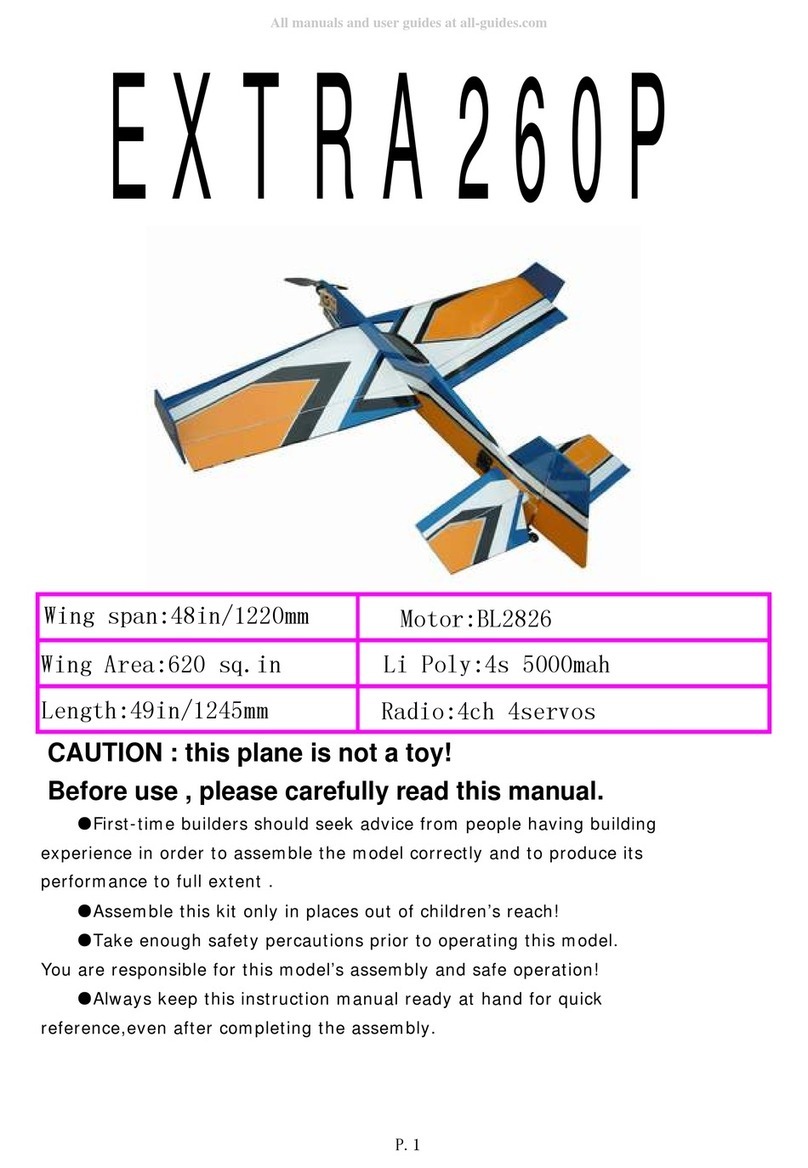
Hobby King EXTRA260P User manual

Hobby King

Hobby King EXTRA260P User manual

Hobby King Arcus F3A User manual

Hobby King

Hobby King Arcus F3A User manual

Hobby King de Havilland Mosquito TT.35 User manual

Hobby King

Hobby King de Havilland Mosquito TT.35 User manual

Hobby King Maestro-46 User manual

Hobby King

Hobby King Maestro-46 User manual

Hobby King PT-17 User manual

Hobby King

Hobby King PT-17 User manual

Hobby King TRAINSTAR User manual

Hobby King

Hobby King TRAINSTAR User manual

Hobby King Skipper 40228 User manual

Hobby King

Hobby King Skipper 40228 User manual

Hobby King Decathlon-46 User manual

Hobby King

Hobby King Decathlon-46 User manual

Hobby King DH 82 Tiger Moth User manual
Hobby King

Hobby King DH 82 Tiger Moth User manual

Hobby King SuperG User manual

Hobby King

Hobby King SuperG User manual

Hobby King Breeze User manual

Hobby King

Hobby King Breeze User manual

Hobby King SBACH 55" User manual

Hobby King

Hobby King SBACH 55" User manual

Popular Toy manuals by other brands

Hasbro TransFormers Energon Quickstrike instructions

Hasbro

Hasbro TransFormers Energon Quickstrike instructions

Fisher-Price HOT WHEELS N9356 Assembly and owner's manual

Fisher-Price

Fisher-Price HOT WHEELS N9356 Assembly and owner's manual

Mattel Hot Wheels City Vs. Robo Beasts Ultimate Garage... instructions

Mattel

Mattel Hot Wheels City Vs. Robo Beasts Ultimate Garage... instructions

LEGO CITY 60003 Assembly manual

LEGO

LEGO CITY 60003 Assembly manual

PlayMonster Fuzzikins Unicorn Sleepover FF009 instructions

PlayMonster

PlayMonster Fuzzikins Unicorn Sleepover FF009 instructions

AzurPoly Bede BD-5J Quick reference guide

AzurPoly

AzurPoly Bede BD-5J Quick reference guide

Lionel FastTrack Graduated/Elevated Trestles owner's manual

Lionel

Lionel FastTrack Graduated/Elevated Trestles owner's manual

Rastar Baby Mercedes-Benz SLK Ride-on instructions

Rastar Baby

Rastar Baby Mercedes-Benz SLK Ride-on instructions

Carson Excavator Loader JCB 2.4 GHz instruction manual

Carson

Carson Excavator Loader JCB 2.4 GHz instruction manual

Somogyi home NLR 1 instruction manual

Somogyi

Somogyi home NLR 1 instruction manual

E-FLITE P-40 Warhawk 300 Assembly manual

E-FLITE

E-FLITE P-40 Warhawk 300 Assembly manual

Mattel Barbie Y6858-0520 instructions

Mattel

Mattel Barbie Y6858-0520 instructions

Playskool Lullaby Gloworm quick start guide

Playskool

Playskool Lullaby Gloworm quick start guide

MTHTrains Premier EF-3 Electric Engine Operator's manual

MTHTrains

MTHTrains Premier EF-3 Electric Engine Operator's manual

Jamara MC FIZZ FIZZY BALLS instruction manual

Jamara

Jamara MC FIZZ FIZZY BALLS instruction manual

GRAUPNER BO 209 MONSUN instructions

GRAUPNER

GRAUPNER BO 209 MONSUN instructions

REVELL KIT 4294 Assembly manual

REVELL

REVELL KIT 4294 Assembly manual

BASETech Wave Hunter 1577605 user manual

BASETech

BASETech Wave Hunter 1577605 user manual

manuals.online logo
manuals.online logoBrands
  • About & Mission
  • Contact us
  • Privacy Policy
  • Terms and Conditions

Copyright 2025 Manuals.Online. All Rights Reserved.