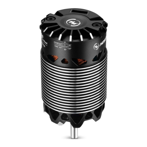
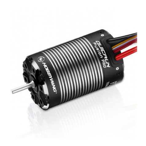
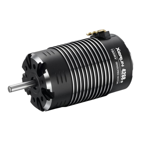
Hobby-Wing XERUN AXE R2 Series User manual

01
Disclaimer
03
Features
02
Warnings
04
Specifications
05
Connections
CAUTIONS
Thank you for purchasing the HOBBYWING’s XERUN AXE Brushless
System! Brushless power systems can be very dangerous. Any
improper use may cause personal injury and damage to the product
and related devices. We strongly recommend reading through this
user manual before use. Because we have no control over the use,
installation, or maintenance of this product, no liability may be
assumed for any damage or losses resulting from the use of the
product. We do not assume responsibility for any losses caused by
unauthorized modifications to our product. We, HOBBYWING, are
only responsible for our product cost and nothing else as result of
using our product.
ATTENTION
ATTENTION
Please make sure that the two arrows align when connecting, otherwise you may damage the inner part of the connectors and cause the power system to function
abnormally. Remember, never connect/disconnect them forcibly.
This is an extremely powerful brushless motor system. For your safety and the safety of those around you, we strongly recommend removing your pinion gear before
performing calibration and programming functions with this system, and keeping wheels in the air when you turn on the ESC.
ATTENTION
• Apply FOC(Field Oriented Control) driving mode to the power system of rock crawler. The low speed torque Is very strong, it is better than ordinary sensored brushless power system or
even better than the brushed power system.
• The chip-type magnetic encoder inside the motor guarantees consistency between three phases’ signals and always outputs the pure and precise signals indicating the rotor position.
• The waterproof and dust-proof design (*IP67 standards) allows the AXE brushless power system to be used in all weather & track conditions without any issue of damage caused to the
system from water or dust. Damage to the vehicle caused by water, mud, or conditions should be monitored closely when running in muddy, wet, or adverse conditions.
• Intelligent torque output & speed closed-loop control for easy control, and consistent motor RPM under all loads.
• The adjustable drag brake & drag brake rate control with the maximum drag brake of up to 200% (that’s nearly twice the drag brake of standard brushless power systems) can provide
unprecedented parking capacity on slopes, with no jerky stops.
• The innovative built-in Bluetooth connectivity allows users to read ESC data or update ESC firmware via a smart phone (installed with the HW LINK app).
• Multiple protections: low-voltage cutoff, thermal, fail safe (throttle signal loss), motor lock-up, over current, and battery reversal.
• It supports dual operation mode, not only classic "Forward and Reverse (rock crawler)" mode, but also "Forward/Reversewith brake (normal)" mode.
1. Cooling Fan Installation (Optional)
When pairing the ESC with a 550 motor, we recommend installing the matching cooling fan. The cooling fan can be powered by the receiver.
2. Motor Wiring
The XERUN AXE brushless ESC only supports the XERUN AXE series of FOC brushless motors. The Axe ESC it cannot be paired with any other type of motor. The Axe Motor, cannot be
used with any other type of ESC.
There is strict wiring order from the ESC to the motor, the three A/B/C ESC wires must connect to the three A/B/C motor wires correspondingly. Next, connect the ESC sensor wire to the
motor sensor wire. Never change the order of your motor wires or damage will occur.
3. Receiver Wiring
The throttle control cable on the ESC has to be plugged into the throttle (TH) channel on the receiver. The throttle control cable (the Red wire) provides an output voltage of 6V/7.4V to
the receiver and steering servo, hence, no separate battery can be connected to the receiver. Improper wiring of any external BEC, or battery pack will result in damage to your ESC.
4. Battery Wiring
Proper polarity is essential. Please ensure positive (+) connects to positive (+), and negative (-) connects to negative (-) when plugging in the battery! When reverse polarity is applied to
the ESC from the battery, it will not function.
06
ESC Setup
Set the Throttle Range - ESC Calibration - Radio Setup
1
In order to make the ESC match the throttle range, you must calibrate it when you begin to use a new ESC. If you install a new radio system, or make changes to your throttle/brake values in
your transmitter, you must redo the ESC Calibration Process.
Failure to calibrate the ESC to your radio system will result in the ESC not working correctly.
We strongly recommend activating the “Fail Safe” function of the radio system and set it (F/S) to “Output OFF” or set its value to the “Neutral Position” to ensure the motor can be stopped
when there is no signal received from the transmitter.
About setting the throttle range, please follow the following steps:
Power On/Off & Warning Tones
2
1) Power ON/OFF:
(Start with the ESC turned off), press the ON/OFF button to turn on the ESC;
(start with the ESC turned on) press and hold the ON/OFF button to turn off the ESC.
2) Warning Tones: Turn on the ESC in the normal way (that is to turn it on without holding the SET button); the motor will beep the number of LiPo cells you have plugged in.
For example, 3 beeps indicate a 3S LiPo.
Programmable Items
3
1. Running Mode
Option 1: Forward and Reverse
This mode is often used by special vehicles (rock crawler). It adopts the “SINGLE-CLICK” method. The vehicle will reverse immediately when you push the throttle trigger forward.
Option 2: Forward/Reverse with Brake
This mode provides the braking function, it’s usually for training. “Forward/Reverse with Brake” mode adopted the “DOUBLE-CLICK” method, that is your vehicle only brakes (won’t reverse)
when the 1st time you push the throttle trigger forward (away from you) (1st push). If the motor stops when you quickly release the throttle trigger and thenre-push the trigger quickly (2nd
push), the vehicle will reverse. If the motor does not stop, then your vehicle won’t reverse but brake, you need to push the throttle trigger one more time. The vehicle only reverses after the
motor stops. This method is for preventing vehicle from being accidentally reversed.
2. Cutoff Voltage
Low Voltage Cutoff for LiPo Protection. This item is mainly for preventing the LiPo pack from over-discharge. If the low-voltage cutoff protection is enabled, the ESC will monitor the battery
voltage all the time and gradually reduce the output to 50% (in 3 seconds) and cut it off 10 seconds later when the voltage goes below the cutoff threshold. The Red LED will flash a single
flash that repeats (☆-, ☆-, ☆-....) when the ESC enters the low-voltage cutoff protection. The ESC will not cut off the power when the voltage is low if the low-voltage cutoff protection is
disabled. We don’t recommend setting the “Cutoff Voltage” to “Disabled” when using a LiPo pack, otherwise, the battery will be damaged due to over-discharge.
• NiMH - For a NiMH pack, we recommend setting this item to “Disabled”.
• Voltage - The specific voltage values correspond to “Low/Intermediate/high” are 3.0V/3.2V/3.4V per cell. Please note, due to a number of variables you may not see exactly these same
voltage values.
3. RPM/Throttle Matching
The speed/RPM will change when the vehicle encounters obstacles or terrain changes based on the loads (on the vehicle), so changing this setting (with the throttle input remains
unchanged) can change the resistance to maintain the speed/RPM.
With the throttle input remains unchanged, setting this item to “Low” allows you to have the kind of feeling that a brushed motor will bring you, then the speed/RPM will be significantly
influenced by the resistance change; setting it to “High” allows you to have a remarkable feeling of speed-governing, that is the speed will change seldom due to the resistance change and
the speed/RPM remains almost unchanged.
In simple terms, set it to “Low” if you like the feeling that a brushed motor will bring you or set it to “High” if you like a more stable speed/RPM when the throttle input remains
unchanged, (it’s “Intermediate” by default, ) so please set it as per your preference.This setting is only valid in "Forward and Reverse (rock crawler)" mode!
4. Max. Forward Force
It’s the force when throttle trigger is at the full throttle position. It’s adjustable among 25%, 37.5%, 50%, 62.5%, 75%, 87.5% and 100% (by default). You can lower down the value for
better driving feel/control when you drive a crawler (simulation model) over difficult terrains (and don’t have any requirement against the maximum speed).
5. Max. Reverse Force
The reverse force of the value will determine its speed. For the safety of your vehicle, we recommend using a low amount.
6. Turbo Timing
This item is adjustable from 0 degree to 10 degrees, the corresponding turbo timing (you set) will initiate at full throttle. It’s usually activated on long straightaway and makes the motor
unleash its maximum potential. Turbo timing adds “RPM” at full throttle.
7. Turbo Delay
When “TURBO DELAY” is set to “INSTANT”, the Turbo Timing will be activated when throttle trigger is moved to the full throttle position. When other value is applied, you will need to hold
the throttle trigger at the full throttle position (as you set) till the Turbo Timing initiates.
8. Drag Brake Force
It is the braking power produced when the throttle is at the neutral position. (Attention! Drag brake will consume more power and heat will be increased, apply it cautiously.). Higher drag
brake means stronger hold or hill brakes.This setting is only valid in "Forward and Reverse (rock crawler)" mode!
9. Drag Brake Rate
It’s the rate at which the drag brake increases to the preset value. This feature slows down how rapidly the ESC applies brakes. Lower values are slower and prevent sudden stops or jerky
stopping movements. You can choose the drag brake rate from level 1 (very soft) to level 9 (very aggressive).
In Auto mode, the ESC adjusts the brag brake rate automatically as per the current speed. The higher the current speed, the lower the drag brake rate (when releasing the throttle trigger to
the neutral position); the lower the current speed, the higher the drag brake rate. It can not only help prevent vehicle from flipping over or the drivetrain from damage due to the rapid
intervention of drag brake when driving at a high speed but also guarantee the sensitive control feel when driving at a low speed. This setting is only valid in "Forward and Reverse
(rock crawler)" mode!
10. Neutral Range
As not all transmitters have the same stability at “neutral position”, please adjust this parameter as per your preference. You can adjust to a bigger value when this happens. The neutral
range is the “dead zone” or “dead band” of the throttle/brakes. If you notice inconsistent drag brakes, you would increase your neutral range value.
11. Start Mode/(Punch)
You can choose the punch from level 1 (very soft) to level 9 (very aggressive). This feature is very useful for preventing tires from slipping during the starting-up process. In addition, “level
7” and “level 9” have strict requirement on battery’s discharge capability. It may affect the starting-up if the battery discharges poorly and cannot provide large current in a short time. The
car stutters or suddenly loses power in the starting-up process indicating the battery’s discharge capability is not good, and you need to reduce the punch or reduce the pinion gear size.
12. BEC Voltage
Option 1: 6.0V
It’s applicable to ordinary servos. Do not use this option with high voltage servos; otherwise your servos may not function normally due to insufficient voltage.
Option 2: 7.4V
It’s applicable to high voltage servos. Do not use this option with ordinary servos; otherwise your servos may be burnt due to high voltage.
13.Motor Rotation
This feature allows the changing of the motor’s forward direction. To check, look at the motor with the shaft facing you. If the motor spins counter clockwise if this item is set to CCW; the
motor spins clockwise if set to CW. The drive train of your chassis will determine what direction motor you should use. Some vehicles use normal or CCW rotation, other vehicles use CW or
backwards rotation motors.
ESC Programming & Firmware Upgrade - The Axe ESC is Only Adjustable using the HW Link App and a Bluetooth enabled Smart Phone
4
1) Program your ESC with a smart phone (installed with the HW LINK app)
• Download and install the Hobbywing’s official app “HW LINK” on your smart
phone. For smart phones with the iOS operating system, please search
“Hobbywing” in the App Store; for smart phones with the Android operating
system, search “Hobbywing” in the Google Play or download it from our website
or scan the following QR code to download it.
• Connect a battery to the ESC and turn it on, then open the Hobbywing official
app“HW LINK” on your smart phone.
It will ask if you want to connect “Bluetooth” or “WiFi” the first time when you
open the app; at this point, please select “Bluetooth”. You need to change the
connection to “Bluetooth” after using the “WiFi” connection, you can click
“Settings” (on the home page) and then “Select the connecting mode” to change the connection.
A list of Bluetooth devices will pop out when you click the ESC icon on the upper right corner, then select the ESC you
want to program to establish the Bluetooth connection between the ESC and smart phone. (Note: the default name &
password of the Bluetooth device are HW_BLE**** & 888888 respectively.)
• Click “Parameters” (on the home page) to adjust the ESC parameters, click the ESC icon on the upper right corner to
disconnect the Bluetooth connection between the ESC and smart phone after completing and saving the adjustments.
2) Firmware Upgrade with a smart phone (installed with the HW LINK app)
• Download and install the Hobbywing’s official app “HW LINK” on your smart phone.
• As you enter the app, click Settings→About→Check for updates to ensure that the database and software version of your ESC are the latest.
• Connect a battery to the ESC and then turn it on, open the “HW LINK” app on your smart phone, a list of Bluetooth devices will pop out when you click the ESC icon on the upper right
corner, then select the ESC (Bluetooth device) you want to program to establish the Bluetooth connection between the ESC and smart phone.
(Note: the default name & password of the Bluetooth device are HW_BLE**** & 888888 respectively.)
• Click “Firmware upgrade” and then “Select the target version” to select the firmware version you need, and then click “Update” to upgrade your ESC. After the upgrade, you can adjust
the parameters via “Parameters” and click the ESC icon on the upper right corner to disconnect the Bluetooth connection between the ESC and smart phone after saving the adjustments.
• During the upgrade process, please ensure that the network connection is stable and do not upgrade your ESC at any place with strong interference.
In addition, please ensure that the smart phone is fully charged and the battery connected to the ESC still has sufficient power and it’s firmly connected to the ESC.
Do not disconnect the battery during the upgrade process, as that may cause the ESC to get damaged or be unable to function.
• When connecting the Bluetooth device (your ESC), please ensure the connection between the ESC sensor wire and the motor sensor wire is normal, otherwise the
Bluetooth device cannot be connected and programmed.
ATTENTION
07
Explanations for Different Status LEDs
08
Trouble Shooting
Factory Reset
5
• Restore the default values (ESC parameters & Info about the Bluetooth module) with the SET button
Turn on the ESC, press and hold the Set button for over 3 seconds.
Pressing and holding the SET button for over 3 seconds at any time when the throttle stick is at the neutral position (except during the ESC calibration or programming), can
factory reset your ESC. The Red & Green LEDs flash at the same time indicating the factory reset is successful. The default values only take effect after you turn the ESC off and
then on again.
Attention! This method will also factory reset the Bluetooth device.
• Restore the default values (only the ESC parameters) with a smart phone (installed with the HW LINK app)
After entering the app and establishing the Bluetooth connection between the ESC and smart phone, click “Factory Reset” in “Parameters” to factory reset your ESC.
After that, please re-calibrate the throttle range.
Automatic Motor Pairing (Optional)
6
You must do the “automatic motor pairing” (as explained below) when any of the following situations occurs:
1) Updated the ESC firmware,
2) Issues like loose rear endplate, severe impact, or abnormal heat (during the operation) abnormal power output occurs to the motor,
Steps of “Automatic Motor Pairing”
Step1: Unplug the throttle wire from the receiver, and then remove the pinion gear (or you can hold the vehicle in the air and remove the wheels, but the effect won’t be that good);
Step2: Connect a battery (to the ESC), turn it on, press and hold the SET button for 3 seconds after it completes the self test to enter the “automatic motor pairing”, the motor
will spin a while during the process.
Step3: The ESC will automatically re-start and beep out the number of the LiPo cells you’ve plugged in after the pairing completes, after that, please re-plug the throttle wire into
the receiver, and then the power system will be ready.
1. During the Starting-up Process
• The Red LED keeps flashing rapidly indicating the ESC doesn’t detect any throttle signal or the neutral throttle value stored on your ESC may be different from the current value stored
on the transmitter. - Redo the ESC calibration Process if your ESC is flashing and not working.
• The Green LED flashes “N/ (number of)” times indicating the number of LiPo cells you have plugged in.
2. In Operation - What lights you should see.
• The Red & Green LEDs go out when the throttle trigger is in throttle neutral zone.
• The Red LED turns on solid when your vehicle runs forward. The Green LED will also come on solid when pulling the throttle trigger to the full (100%) throttle endpoint and setting the
“Max. Forward Force” to 100%.
• The Red LED turns on solid when you brake the vehicle, the Green LED will also come on solid when pushing the throttle trigger to the full brake endpoint and setting the
“Max. Reverse Force” to 100%.
3. Error or Warning LED CodesN
• The Red LED flashes a short, single flash that repeats (☆, ☆, ☆) indicating the low voltage cutoff protection is activated.
• The Green LED flashes a short, single flash that repeats (☆, ☆, ☆) indicating the ESC thermal protection is activated.
• The Green LED flashes a short, double flash that repeats (☆☆, ☆☆, ☆☆) indicating the motor thermal protection is activated.
• The Green and Red LEDs flash a short, double flash that repeats (☆☆, ☆☆, ☆☆) indicating the power system stops functioning due to “sensor issue”. In that case, please check if
the ESC sensor wire has been firmly connected to the motor sensor wire before resuming the operation.
• Ensure all wires and connections are well insulated before connecting the ESC to related devices, as short circuit will damage your ESC.
• Ensure all devices are well connected to prevent poor connection that may cause your vehicle to lose control or other unpredictable issues such as damage to the device.
• Read through the manuals of all power devices and chassis and ensure the power configuration is correct before using this unit.
• Please use a soldering iron with the power of at least 60W to solder all input/output wires and connectors.
• Do not hold the vehicle in the air and free rev it to full throttle, as rubber tires can “expand” to extreme size or even crack to cause serious injury, or damage to your system can occur.
• Never allow the ESC & motor temperatures (external temp.) go above 90/194, as high temperature may cause damage to both the ESC and motor.
• Always disconnect the batteries when your vehicle is not in use. The ESC will continue to drain current if it is connected to batteries (even if the ESC is turned off). Extended battery
connection (Even when off) will cause batteries to completely discharge and result in damage to batteries or ESC. This WILL NOT be covered under warranty.
• The ESC must be Calibrated or setup to your radio system before normal operation.
USER MANUAL
XERUN AXE R2 Brushless System
PN
Cont./Peak Current
Motor Type
Applications
LiPo/NiMH Cells
BEC Output
Connectors
Size/Weight
ESC Programming
30112102
80A/480A
Only the XERUN AXE R2 Series
1/10th Rock Crawler
2-3S Lipo,6-9 Cells NiMH
6V/7.4V Switchable, Continuous Current of 6A
Input/Output Ends: No Connectors
47.4(L)x36.2(W)x26.5(H)mm/ 108g (Included input wires)
iOS or Android smart phone (installed with the HW LINK app)
Model XERUN AXE R2 Brushless ESC
30401253
30401254
30401255
30401256
XERUN AXE540L R2-1400KV-FOC
XERUN AXE540L R2-2100KV-FOC
XERUN AXE540L R2-2800KV-FOC
XERUN AXE550 R2-3300KV-FOC
PN Motor Model
1400KV
2100KV
2800KV
3300KV
KV
(No-load)
2-3S
2-3S
2-3S
2-3S
LiPos
36.9
18.6
12.7
8.4
Resistance
1.7A
2.7A
3.6A
4.7A
No-load
Current
Motor Diameter
Length
Shaft Diameter
Length Poles
211g
212g
213g
247g
Weight
36.0/57.8 mm
1.42/2.28 in
3.175/16.0 mm
0.125/0.63 in
36.0/63.8 mm
1.42/2.51 in
5/16.0 mm
0.197/0.63 in
4
Please ensure that the ESC sensor wire has been plugged into the motor sensor wire and screwed up, otherwise the water may get inside and damage the ESC or motor.
Note: those black-and-white options are default values.
Trouble(s) Solution(s)Possible Causes
1. No power was supplied to the ESC.
2. The ESC switch was damaged.
1. Check if all ESC & battery joints or connections have been well
soldered or firmly connected.
2. Replace the switch.
The ESC was unable to start the status LED, the motor after
it was powered on.
1. The ESC didn’t detect any throttle signals.
2. The neutral throttle value stored on your ESC is different from
the one stored on the transmitter.
1. Check if the throttle wire is reversely plugged in or in the wrong
channel and if the transmitter is turned on.
2. Re-calibrate the throttle range after you release the throttle trigger
to the neutral position.
After the ESC was powered on and finished LiPo detection,
the GREEN LED flashed N times, and then the RED LED flashed.
The default motor direction didn’t match the chassis. Set the motor direction/rotation to the other option via the HW LINK app.
The vehicle ran backward when you pulled the throttle trigger
towards you.
1. The receiver was influenced by some foreign interference.
2. The ESC entered the LVC protection.
3. The ESC entered the ESC thermal protection.
4. The motor entered the ESC thermal protection.
1. Check all devices and try to find out the possible causes, and check
the transmitter’s battery voltage.
2. The Red LED keeps flashing indicating the LVC protection is activated,
please replace the battery.
3. The Green LED keeps flashing indicating the ESC thermal protection is
activated. Please let it cool again before using the ESC again.
4. It is over temperature protection of motor if green light flashes
continuously (double flash). Please continue touse it after the
temperature of motor reduces.
The motor suddenly stopped or significantly reduced the
output in operation.
1. “Sensor wire connection” issue.
2. ESC problem.
1. Check if the ESC & motor sensor wires are damaged and re-connect
them and re-start the ESC after confirming that there is no sensor issue.
2. Contact the dealer for customer service.
The vehicle couldn’t be started or stopped halfway, and the
Red & Green LEDs flashed a short, double flash that repeated.
The ESC and motor didn’t do "Automatic Motor Pairing" Please make "Automatic Motor Pairing" according to the manual part 6.6.
The motor is very hot during running after upgrading
firmware of ESC.
1. The neutral position on the transmitter was not stable,
so signals were not stable either.
2. The ESC calibration was not proper.
1. Replace your transmitter.
2. Re-calibrate the throttle range or fine tune the neutral position on
the transmitter.
The car ran forward/backward slowly when the throttle trigger
was at the neutral position.
1. The ESC throttle cable wasn’t plugged in the correct channel
on the receiver.
2. The ESC throttle cable was reversely plugged in.
3. The throttle range stored on your ESC is different from the
one stored on the transmitter.
1. Plug the throttle cable into the throttle (TH) channel on your receiver.
2. Plug in the throttle cable properly by referring to relevant mark shown
on your receiver.
3. If you’re using a Futaba transmitter, set the throttle to “REV”;
if other transmitters, please try to keep the ratio between “Forward”
and “Reverse” on the throttle channel at 5:5.
When pressing the SET button to set the throttle neutral
position, the GREEN LED didn’t flash and no beep was emitted,
or you were unable to set the full throttle endpoint and the full
brake endpoint after the neutral position was accepted.
The battery voltage was beyond the normal range. Check if the battery voltage is within the regulated range.
The ESC was unable to start the motor but beeped
“B-B-, B-B, B-B-” (the time interval was 1s) and the Green LED
on the ESC flashed.
Move the throttle trigger to the neutral position and
press the SET button.
3. Set the neutral point, the full throttle endpoint and the full brake endpoint.
• Leave the throttle trigger at the neutral position, press the SET button, the RED LED dies out and the GREEN LED flashes 1 time and the motor beeps 1 time to accept the neutral position.
• Pull the throttle trigger to the full throttle position, press the SET button, the GREEN LED blinks 2 times and the motor beeps 2 times to accept the full throttle endpoint.
• Push the throttle trigger to the full brake position, press the SET button, the GREEN LED blinks 3 times and the motor beeps 3 times to accept the full brake endpoint.
4. The motor can be started 3 seconds after the ESC/Radio calibration is complete.
The Green LED
flashes once and
motor emits
“Beep” tone.
Move the throttle trigger to the end position of forward
and press the SET button.
The Green LED flashes
twice and motor emits
“Beep-Beep”
tone.
Move the throttle trigger to the end position of
backward and press the SET button.
The Green LED flashes
three times and motor
emits
“Beep-Beep-
Beep” tone.
1. Turn on the transmitter, set parameters on the throttle channel like “D/R”, “EPA” and
“ATL” to 100% (for transmitter without LCD, please turn the knob to the maximum)
and the throttle “TRIM” to 0 (for transmitter without LCD, please turn the
corresponding knob to the neutral position). You don't need to do this step if the
transmitter's settings are default!
2. Start with transmitter on and the ESC turned off but connected to a battery. Holding
the SET button and press the ON/OFF button to turn on the ESC, the RED LED on the
Press and hold the
SET button
Press the
ON/OFF
button
Release the SET
button once the LED
flashes.
ESC starts to flash (Note 1 the motor beeps at the same time), and then release the SET button immediately. (The ESC will enter the programming mode if the SET button is not released
in 3 seconds, then you need to restart from step 1.)
Note 1: Beeps from the motor may be low sometimes, and you can check the LED status instead.
COMBO-XERUN AXE540L R2-1400KV-FOC System
COMBO-XERUN AXE540L R2-2100KV-FOC System
COMBO-XERUN AXE540L R2-2800KV-FOC System
COMBO-XERUN AXE550 R2-3300KV-FOC System
PN COMBO
38020311
38020312
38020313
38020314
20200924
Instant
Programmable Item
Running Mode
Cutoff Voltage
RPM/Throttle Matching
Max. Forward Force
Max. Reverse Force
Turbo Timing
Turbo Delay
Drag Brake Force
Drag Brake Rate
Neutral Range
Start Mode (/ Punch)
BEC Voltage
Motor Rotation
Option 1
Forward and
Reverse
Disabled
Low
25%
25%
Level 1
Level 1
6.0V
CCW
Item #
1
2
3
4
5
6
7
8
9
10
11
12
13
Option 2
Forward/Reverse
with Brake
Low
Intermediate
37.5%
37.5
0.1s
Level 2
Level 2
7.4V
CW
Option 3
Intermediate
High
50%
50%
0.2s
Level 3
Level 3
Option 4
High
62.5%
62.5%
0.3s
Level 4
Level 4
Option 5
75%
75%
0.4s
Level 5
Level 5
Option 6
87.5%
87.5%
0.5s
Level 6
Level 6
Option 7
100%
100%
Level 7
Level 7
Level 8
Level 8
Level 9
Level 9
6-17% (default: 10%)
50-200% (default: 80%)
0-10 degrees adjustable (default: 0 degree)
Option 8 Option 9
XERUN AXE R2 Brushless Motor
XERUN AXE R2 Brushless ESC

编程及固件升级方法
4
ATTENTION
· 更新过程中,请确保网络环境稳定,不要在强干扰区域操作。确保移动设备电量充足,给电调供电的电池电量充足并连接牢固。更新过程中出现中断
可能导致电调固件损坏而令电调无法使用。
· 连接蓝牙时,请务必确认有感线连接正常,否则蓝牙无法连接并设置。
感谢您购买本产品!无刷动力系统功率强大,错误的使用可能造
成人身伤害和设备损坏。我们强烈建议您在使用设备前仔细阅读
本说明书,并严格遵守规定的操作程序。我们不承担因使用本产
品而引起的任何责任,包括但不限于对附带损失或间接损失的赔
偿责任;同时,我们不承担因擅自对产品进行修改所引起的任何
责任。我们有权在不经通知的情况下变更产品设计、外观、性能
及使用要求。
参数说明
3
1.启动阶段
1) 红灯持续快速闪烁:电调未检测到油门信号或电调油门中点与控不匹配。
2) 绿灯闪烁N次:锂电节数检测,闪烁N次表示当前锂电为N 节。
2.行驶阶段
1) 油门摇杆处于中点区域,LED灯熄灭。
2)前进时,红色LED恒亮;当油门处于正向最大且最大前进力度为100%时,红色和绿色LED恒亮。
3)倒车时,红色LED恒亮;当油门处于反向最大且最大倒车力度设为100%时,红色和绿色LED恒亮。
3.相关保护功能触发时,LED状态含义:
1) 红灯持续闪烁(单闪,“☆,☆,☆”):电调进入低压保护状态。
2) 绿灯持续闪烁(单闪,“☆,☆,☆”):电调温度过高,电调进入过热保护状态。
3) 绿灯持续闪烁(双闪,“☆☆,☆☆,☆☆”):电机温度过高,电调开启电机过热保护功能。
4) 红绿灯同步双闪(双闪,“☆☆,☆☆,☆☆”):有感运行出现问题,动力系统停止工作,需确保有感线连接无问题后重新开机。
ATTENTION
· 电调与相关连接部件连接前,请确保所有电线和连接部件绝缘良好,短路会毁坏电调。
· 请务必仔细连接好各部件,若连接不良,您可能不能正常控制赛车,或出现设备损坏等其他不可预知的情况。
· 使用此电调前,请认真查看各动力设备以及车架说明书,确保动力搭配合理,避免因错误的动力搭配导致电机超载,最终损坏电调。
· 若需对电调的输入输出线、插头做相关焊接时,为保证焊接牢靠,请使用至少60W功率的焊接设备进行焊接。
· 高速运行中,因车子轮胎会“膨”到极致,故而请勿将车子腾空然后加至全速,否则,轮胎可能爆裂而引起严重伤害。
· 勿使电调和电机的外部温度超过90℃/194℉,高温将会毁坏电调并且可能导致电机损坏。
· 使用完毕后,切记断开电池与电调的连接。如电池未断开,即使电调开关处于关闭状态,电调也会一直消耗电能,长时间连接电池最终会被完全放电,进而导致电
池或电调出现故障。我们不对因此而造成的任何损害负责!
· 将FOC(磁场定向控制)驱动方式用于攀爬车动力系统,低速扭力非常强大,远超普通有感无刷动力系统,甚至比有刷动力还要更好。
· RC业界首创,将FOC(磁场定向控制)驱动方式用于攀爬车动力系统,低速扭力非常强大,远超普通有感无刷动力系统,甚至比有刷动力还要更好。
· 整套动力防护等级IP67,出色的防水防尘性能,在各种气候条件下,整套动力轻松应对含有泥沙、冰雪、积水的复杂路面。
· 智能化扭矩输出及速度闭环控制,操控得心应手。
· 细腻专业的拖刹调节,最大拖刹力度更是可以设置到200%,即拖刹力度约为普通无刷动力系统的两倍,提供史无前例的坡道驻车能力。
· 创新的电调内置蓝牙模块,不需其他设备即可通过蓝牙连接手机APP进行参数设置,数据读取,固件升级等操作,简单方便。
· 电机内置芯片磁编码传感器,三相信号一致性好,始终输出纯净的、准确的转子位置信号。
· 多重保护功能:电池低压保护、过热保护、油门失控保护、堵转保护、电流保护、电池防反接保护。
· 支持双运行模式,既支持经典“直接正反转(攀爬)”模式,也支持“正反转带刹车(普通)”模式。
·开关机说明:关机状态下短按ON/OFF键开机;开机状态下长按ON/OFF键关机。
·开机鸣音说明:在正常情况下开机(即不按住 SET 键的情况下开机), 电机会发出几声“哔”鸣音表示锂电节数。例如: “ 哔哔哔”表示3节锂电。
对插时注意将两个接口处箭头对齐,否则可能损坏插头内部结构导致动力系
统不能正常运行,切勿强行插拔。
本系统功率强劲,为了您及周边他人的安全,我们强烈建议您在校准及设定
该系统前拆下电机小齿,并在车轮悬空的情况下开启电调上的控制开关!
ATTENTION
请务必确保感应线插好,且旋紧,否则可能感应线进水,进而损坏电调或电机!
电调第一次使用前或遥控器更改过油门通道“TRIM”微调、D/R、EPA等参数后,均需重设油门行程,不然可能会导致电调无法使用或误动作。 另外我们强烈建议同时
开启遥控器的失控保护功能,将遥控器油门通道的无信号保护(“F/S”)功能设置为关闭输出方式或将保护值设置为中点位置,使得当接收机无法收到遥控器信号后,
电机能够停止运转。
油门校调步骤如下图所示:
以下黑底白字的选项为可编程项目的默认参数值。
故障现象 解决方法可能原因
1、电池电压没有输入到电调;
2、电调开关损坏。
电池组电压不在正常范围内
1)电调未检测到油门信号;
2)电调油门中点与遥控器不匹配。
电机默认转向设置与车架不匹配
1、接收机遇到干扰;
2、电调进入电池低压保护状态;
3、电调进入过温保护状态。
4、电机进入过温保护状态
1、遥控器中位有所漂移,信号不稳;
2、油门行程没校准好。
1、有感线连接出现问题;
2、电调故障。
1、检查电源输入通路是否有焊接不良情况,并重新焊好;
2、更换开关。
检查电池组电压。
1)检查油门线是否插反、通道是否插错、控是否有开启;
2)油门归中位,重新校准油门行程。
通过APP将默认转向设置为另外一项
1、检查接收机出现干扰的原因,检查发射机器电池电量;
2、红灯持续闪烁为电压保护,请更换电池;
3、绿灯持续闪烁为温度保护,请等电调温度降低后继续使用。
4、绿灯持续闪烁(双闪)为电机过温保护,请等电机温度降低后继续使用。
1、更换信号稳定的摇控器;
2、重新校准油门行程,或使用控的油门微调校准中点。
1、检查有感线有无破皮折断等现象,确保无误后重新连接并重新开机
2、联系经销商处理维修事宜。
1、将油门线插到接收机标示的Throttle通道。
2、查看接收机标示,确保电调油门线正确插入接收机。
3、若是Futaba遥控,将油门设为“REV”,其他遥控也尽量
保持油门通道前后比例为5:5
1、检查有感线有无破损,接口处有无旋紧,有无进水现象
2、返厂检测维修
上电后电机无法启动,发出“哔-哔-,哔-哔-”警示
音且伴有绿灯闪烁(每组双音间隔时间为1秒)
上电完成锂电节数检测后(闪N次绿灯),红灯闪烁
上电后指示灯不亮,电机无法启动
遥控器正向加大油门,车子反而倒退
无法启动或使用中途停车,伴随红绿灯双闪
电调与电机未做自适应配对 请参照说明书做适应配对电调升级固件后,电机运行特别热
油门在中点时,车子缓慢前进或缓慢后退
设定油门行程时,按下Set键设中点时,绿灯不闪且无
“哔”音,或设完中点后,无法设置正向及反向最大点
正常操作时,电机有有抖动等速度不稳定的情况
电机转动过程中,突然停转或功率输出显著降低
1、电调油门线未插到接收机正确的通道
2、电调油门线插反
3、油门通道设置与电调不匹配
1、有感连接异常
2、电机或电调故障
03
产品特色
02
注意事项
04
产品规格
05
连接电子调速器
06
设置电子调速器
CAUTIONS
ATTENTION
设定油门行程
1
开关机及鸣音说明
2
1) 利用SET键恢复出厂设置(含蓝牙信息),方法如下:
在油门摇杆处于中立点位置的任意时刻(除进行油门校调或编程设定时),按住 SET 键3秒以上,可恢复出厂设定。红绿灯同时闪烁时表示恢复设定成功,出厂设定
需重新上电方可生效。
注意:此方式会把蓝牙信息恢复为出厂默认值!
2) 利用APP恢复出厂设置(仅复位电调参数),方法如下:
进入APP连接电调后,点击APP内参数设置中的的恢复出厂设置完成出厂设定恢复。恢复出厂设置后,请重新设置油门行程。
恢复出厂设定
5
当出现以下情况时,请务必做下自适应配对:
1)电调更新了固件;
2)电机如果出现过尾盖松动,承受过剧烈撞击,或者有运行时发热异常,动力输出不正常等情况
自适应配对方法:
步骤1:将油门线从接收机内拔出,将电机齿拆下(车辆悬空并把轮子拆掉也可以,但效果略差);
步骤2:接好电池,电调开机,待电调自检完成之后,长按SET键3秒,进入电机自动适配过程,整个过程电机都会产生一定的转动
步骤3:适配步骤完成后,电调会重启并报锂电池节数,之后重新接好油门线即可正常操作。
电机自适应配对(非必做项)
6
07
电调状态指示灯(LED)说明
08
故障快速处理
1、运行模式(Running Mode):
选项1:直接正反转(攀爬)
此模式采用单击式倒车方式,即油门摇杆从中点区域推至反向区域时,电机立即产生倒车动作,该模式一般用于攀爬车辆。
选项2:正反转带刹车(普通)
此模式则提供了倒车功能,通常用于训练。“正反转带刹车”模式采用双击式倒车方式,即油门摇杆在第一次从中点区域推至反向区域时,电机只是刹车,不
会产生倒车动作;当油门摇杆快速回到中立点区域并第二次推至反向区域时,如果此时电机已停止,则产生倒车动作 ,如果电机未停止,则不会倒车,仍是
刹车,需要再次将油门回到中点并推向反向区, 此时如果电机已经停止才会倒车,这样做的目的是防止车辆行驶过程中因多次点刹而造成误倒车。
2、低压保护阈值(Low Voltage Cut-Off Threshold):
这项功能主要是防止锂电池过度放电而造成不可恢复的损坏。如果开启了电压保护,运行中电调会时刻监视电池电压,一旦电压低于设定的阈值,在3秒内动力输出将
逐步降为正常功率的50%,10秒后动力将完全关闭。当进入低压保护后,红色 LED 会以“☆-,☆-,☆-”方式单次循环闪烁。设置为不保护时,电调不会因低
压而切断动力,使用锂电池时,不建议设置为(不保护),否则电池可能因为过放而损坏。对于NiMH电池,建议将此项参数设置为“不保护(No Protection)”。
低、中、高选项分别对应3.0V/3.2V/3.4V每节。
3、扭矩补偿度(RPM/Throttle Matching):
车子在行驶中,因路面的关系,阻力会有所变化,而影响速度;通过设置这个值,在油门量不变时,可以调整车子遇到不同阻力时,保持速度的能力。当油门量不变时,
设为“低”时,类似有刷的操控手感,车速随阻力的变化影响大;设为“高”时,定速感明显,即车速随阻力的变化很少,速度保持的很好。
简单来说,若你喜欢有刷的那种手感,把这个值设低;若你喜欢在油门操持不变时,车速保持的更稳定,则把这个值设大;参数默认为“中”,请根据个人喜好调整这
个值。此设置仅在“直接正反转(攀爬)”模式时有效!
4、最大前进力度(Max. Forward Force):
指油门处于正向最大时的力度,出厂默认值为100%。若因在复杂地形操控攀爬仿真车型而对最大速度要求较低时可以适当降低此值,便于更好的操控。
5、最大倒车力度(Max. Reverse Force):
选择不同的参数值可以产生不同的最大倒车速度(一般情况下推荐使用比较小的倒车速度)。
6、Turbo 进角 (Turbo Timing):
激爆进角。这个是进角的大小设置项,只有在全油门时才会开启,通常用于较长的直道上,释放出马达的最大功率。
7、Turbo延迟时间(Turbo Delay):
是指触发Turbo所需要的持续全油门时长。当持续全油门的时间达到此设定值后,才能触发Turbo 开启。
8、拖刹力度(Drag Brake):
拖刹是指当油门摇杆从正向区域转入中点区域内时,对电机产生一个刹车力(值得注意的是,拖刹也会消耗电量,选择合适的拖刹力度即可)。此设置仅在“直接正
反转(攀爬)”模式时有效!
9、拖刹加速度(Drag Brake Rate):
指遥控扳机进入油门中点区域时拖刹力度由零增加至设置值时的加速度,俗称缓刹,此值分为9级可调,级数越高,拖刹加速度越大,合理设置此值可使车辆停得更稳。
“自动(Auto)”选项为拖刹加速度根据当前速度智能调节,即当前速度越快,油门回中时拖刹加速度越小;速度越慢,回中时拖刹加速度越大。此功能可避免高速
时拖刹介入过快而导致翻车或损坏传动系统,又可在低速时保证灵敏的操纵手感。此设置仅在“直接正反转(攀爬)”模式时有效!
10、油门中点范围(Neutral Range):
油门中立点区域宽度,请根据个人习惯进行调整。有些品质欠佳的遥控器中点位置容易漂移,导致车子缓慢前进或后退,出现此现象时, 请把区域宽度设成更大值。
11、启动模式(Throttle Rate / Punch):
可根据个人习惯、场地、轮胎抓地特性等条件,选择从1级(“非常柔和”)到9级(“非常劲暴”)等9种启动加速度,这个功能对于防止启动时轮胎打滑非常有用。
此外,使用“7级”—“9级”模式时,对电池的放电能力要求较高,若电池放电能力较差,不能提供瞬时大电流,则反而会影响启动效果。当启动时出现停顿或瞬间
失去动力时,则可能是电池放电能力不足引起的,这时需要降低启动加速度,或将齿轮减速比增大。
12、 BEC电压(BEC Voltage):
选项1:6.0V
适用于普通舵机;若使用高压舵机,请勿设为此项,否则可能出现电压不足无法正常工作。
选项2:7.4V
适用于高压舵机;若使用普通舵机,请勿设为此项,否则可能因电压太高而烧坏舵机。
13、电机转动方向(Motor Rotation):
电机轴正面朝向使用者面部(即电机尾部远离使用者面部),遥控器正向加大油门时,若设置成 CCW,电机轴逆时针转动; 若设置成 CW,电机轴顺时针转动。
由于车架结构差异,则有可能转向相反,请以实际为准。若车子转向不对时,更改为相反转向即可。
01
声明
1、安装风扇(非必做项):
电调与550电机搭配使用时,建议安装上配套的风扇,风扇从接收机取电。
2、连接马达:
XERUN AXE 无刷电调仅支持XERUN AXE系列FOC无刷电机,不可搭配其他类型电机使用!
电调与马达相连有严格的线序要求,电调的#A/#B/#C必须与电机的#A/#B/#C三线严格一一对应,将电调与电机的感应口对接。
3、连接接收机:
将电调的油门控制排线插入接收机的油门通道(即THROTTLE通道)。因为排线中的红线输出6V/7.4V电压给接收机及舵机,所以请勿给接收机额外供电,否则可
能损坏电调。
4、连接电池:
电调的输入线有极性之分,插入电池时,请确保电调的(+)极与电池的(+)相连,(-)极与(-)相连。如果电调接反电,电调将不能工作。
AXE Brushless System
使 用 说 明 书
3、此时需要设定三个点:油门中点、正向最高点和反向最高点。
1)油门摇杆留在中点位置,按一下 SET 键,红灯熄灭,绿灯闪烁1次,马达鸣叫“哔”1声,表示已存储中点位置;
2)油门摇杆打到正向最高点,按一下SET键,绿灯闪烁2次,马达鸣叫“哔-哔-”2声,表示已存储油门正向最高点;
3)油门摇杆打到反向最高点,按一下SET键,绿灯闪烁3次,马达鸣叫“哔-哔-哔-”3声,表示已存储油门反向最高点;
4、油门行程校调完毕,三秒钟后,电机即可正常操作。
摇杆置于中点,
按一下SET按钮。
按一下SET键,
绿灯闪烁一下。
摇杆置于正向最高点,
按一下SET按钮。
摇杆置于反向最高点,
按一下SET按钮。
按一下SET键,
绿灯闪烁二下。
按一下SET键,
绿灯闪烁三下。
按住SET键 短按ON/OFF键
红灯LED闪烁
时,立刻松开
按键
1、打开遥控器,将油门通道的“D/R”、“EPA”、“ATL”等参数调到100%(如遥控器无显示屏,则将对应旋钮调到最大位置), 油门通道的中点微调
“TRIM”调为0(如遥控器无显示屏,则将对应旋钮调到中间位置)。若遥控器为默认设置,可以不做此设置!
2、电调关机状态,持续按住SET按键不松开,短按ON/OFF键, 电调上红色LED立即开始闪烁(同时马达鸣叫 备注1),立即松开按键(如果未在3秒内及时松开按
键, 电调将进入参数设定模式, 此时需从步骤1重新开始操作)。
备注1: 马达鸣叫声音可能较小,在这种情况下,观察LED状态即可。
1、通过手机APP与电调通过蓝牙连接进行参数设置,设置方法如下:
· 移动端下载好盈官方APP:HW LINK,iOS直接在App Store中搜索
Hobbywing即可找到;Android在Google Play中查找 Hobbywing
即可找到,或从Hobbywing官网或扫下面的二维码下载。
· 给电调通电并开机,然后在移动端进入官方APP:HW LINK。
首次进入APP,会提示选择蓝牙连接或是WiFi连接,此处选择蓝牙连接。
使用过WiFi连接后如果要切换为蓝牙连接请点击“系统设置”中的“选
择连接方式”改变设置。
点击APP内右上方的电调标识,会弹出附近可连接的蓝牙设备,点选所
需设置的电调名称以连接(蓝牙出厂默认名称:HW_BLE****,出厂默
认密码:888888)
· 点击参数设置以调整电调参数,设置完成并保存后点击右上方的电调图标以断开连接。
2、固件升级方法:
· 移动端下载好盈官方APP:HW LINK
· 进入APP点击系统设置→关于→检查更新,确保数据库和软件版本处于最新状态。
· 给电调通电并开机,点击APP内右上方的电调标识,会弹出附近可连接的蓝牙设备,点选所需设置的电调名称以连接
(蓝牙出厂默认名称:HW_BLE****,出厂默认密码:888888)
· 点击固件升级,点击选择目标版本栏目来选择所需固件版本,然后点击下方的更新开始固件更新操作。更新完成后可通过参数设置修改自己所需参数,保存后点击
右上方的电调图标以断开连接。
20200924
0s
设定项名称
运行模式
低压保护阀值
扭矩补偿度
最大前进力度
最大倒车力度
Turbo进角
Turbo延迟
拖刹力度
拖刹加速度
油门中点范围
启动模式(Punch)
BEC电压
电机转动方向
参数1
直接正反转(攀爬)
不保护
低
25%
25%
1级
1级
6.0V
CCW
编号
1
2
3
4
5
6
7
8
9
10
11
12
13
参数2
正反转带刹车(普通)
低
中
37.5%
37.5
0.1s
2级
2级
7.4V
CW
参数3
中
高
50%
50%
0.2s
3级
3级
参数4
高
62.5%
62.5%
0.3s
4级
4级
参数5
75%
75%
0.4s
5级
5级
参数6
87.5%
87.5%
0.5s
6级
6级
参数7
100%
100%
7级
7级
8级
8级
9级
9级
6-17%可调,默认10%
50-200% ,默认80%
0-10度可调,步进为1度,默认0度
参数8 参数9
XERUN AXE R2 Brushless Motor
XERUN AXE R2 Brushless ESC
PN
持续/峰值电流
支持电机类型
主要适用车型
电池节数
BEC输出
输入/输出
尺寸/重量
参数设定
30112102
80A/480A
仅支持XERUN AXE R2系列电机
1/10攀爬车
2-3S Lipo,6-9 Cells NiMH
6V/7.4V可调,持续电流6A,峰值电流13A
输入XT60,输出无插头
47.4(长)x36.2(宽)x26.5(高)mm/ 108g (含输入线)
手机APP设定(iOS及Android)
电调型号 XERUN AXE R2 Brushless ESC
30401253
30401254
30401255
30401256
XERUN AXE540L R2-1400KV-FOC
XERUN AXE540L R2-2100KV-FOC
XERUN AXE540L R2-2800KV-FOC
XERUN AXE550 R2-3300KV-FOC
PN 电机型号
1400KV
2100KV
2800KV
3300KV
KV值
(空载)
2-3S
2-3S
2-3S
2-3S
适用锂电
36.9
18.6
12.7
8.4
内阻
(mΩ)
1.7A
2.7A
3.6A
4.7A
空载电流 外径/长度 轴径/外露轴长 马达极数
211g
212g
213g
247g
重量
36.0/57.8 mm
1.42/2.28 in
36.0/63.8 mm
1.42/2.51 in
5/16.0 mm
0.197/0.63 in
3.175/16.0 mm
0.125/0.63 in 4
COMBO-XERUN AXE540L R2-1400KV-FOC System
PN COMBO
38020311
COMBO-XERUN AXE540L R2-2100KV-FOC System38020312
COMBO-XERUN AXE540L R2-2800KV-FOC System38020313
COMBO-XERUN AXE550 R2-3300KV-FOC System38020314
This manual suits for next models
12
Other Hobby-Wing Engine manuals
