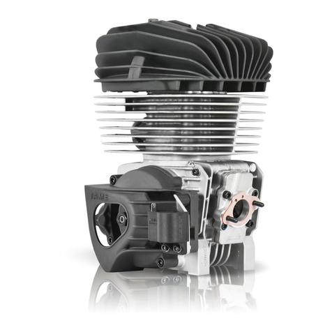
Hobby-Wing QUICRUN Fusion Pro User manual

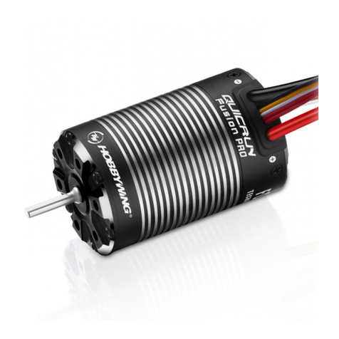
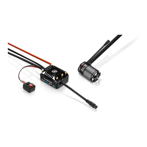
• The integrated design of the ESC and the motor greatly reduces the overall volume and weight, and makes the layout and wiring of car frame simpler and more convenient.
• The FOC driving mode, low speed torque is strong. Smooth running at extreme low speed, which is far superior to the common sensored brushless power system, even better than the brushed power.
• Thanks to the sine wave driving mode, the whole system has high efficiency, small heat, and effectively extends the endurance time; and the motor runs more quietly and soft.
• The protection grade of the whole system is IP67, with excellent waterproof and dustproof performance. Under various weather conditions, the whole system can easily deal with the complex road surface containing silt, ice
and snow, and water.
• Intelligent torque output and speed closed-loop control, fully experience the cruise control and steep slope slow descent function of 1:1 vehicle, making the control handy.
• Active drag brake force adjustment, providing unprecedented parking capacity on slope.
• With strong built-in switch mode BEC, the continuous current is up to 6A, and support switch between 6V and 7.4v, easy to drive various powerful steering servo and high-voltage steering servo.
• Multiple protection functions: battery low voltage protection, overheat protection, throttle lost protection, lock-up protection.
• It supports LED program box to set ESC parameters, and has independent parameter setting interface, which is integrated on electronic switch, making setting parameters more convenient.
• Connect receiver
Insert the throttle cable of the ESC into the throttle channel of receiver (that’s THROTTLE channel). Because the red line of throttle cable output 6V/7.4V voltage to receiver and steering servo, do not supply power to receiver,
otherwise the ESC may be damaged. If need to supply power, pick out the red line among throttle cable, wrap it and suspend.
• Connect battery
The input line of the ESC has polarity. When connecting the battery, make sure that the (+) pole of the ESC is connected to the (+) pole of the battery and the (-) pole is connected to the (-). If the ESC is connected reversely,
the ESC will be damaged. There is no warranty service for damaging ESC due to power on reversely.
Thank you for purchasing this HOBBYWING product! Any improper use may
cause personal injury and damage to the product and related devices. We
strongly recommend reading through this user manual before use and
strictly abide by the specified operating procedures. We shall not be liable
for any liability arising from the use of this product, including but not
limited to reimbursement for incidental or indirect losses. Meanwhile, we do
not assume any responsibility caused by unauthorized modification of the
product. We have the right to change the product design, appearance,
performance and use requirements without notice.
Warning: The power of the system is powerful. For the safety of you
and other people around you, we strongly recommend that you
remove the pinion gear before calibrating and setting the system,
and turn on the control switch of the ESC when the wheel is
suspended!
ATTENTION
Malfunction SolutionCause
1. The battery voltage is not input to the ESC;
2. The switch of ESC is damaged.
1. Throttle signal is not detected by the ESC;
2. The neutral position of ESC and radio is unmatched.
The default rotation direction setting of motor and car
frame is unmatched.
1. The receiver is interfered;
2. The ESC enters low voltage protection;
3. The ESC enters overheat protection.
1. The middle position of radio drifts and the signal is unstable;
2. Throttle range is not calibrated well.
1. The throttle cable of esc is not inserted the correct channel
of receiver, or inserted reversely;
2. Problem with the receiver or transmitter.
1. Check whether the connection between the battery and the esc is good, whether the plug is soldered poorly,
whether there is a problem with the battery;
2.Replace the switch.
1. Check whether the throttle line is inserted reversely, whether the channel is inserted wrongly and whether the radio is on;
2. The throttle return to neutral position. Recalibrate throttle range.
Set the parameter item “Motor Rotation” to the opposite direction via LED program box.
1. Check why the receiver is interfered. Check battery level of transmitter;
2. Red light flashes continuously is low voltage protection, please replace battery;
3. Green light flashes continuously is overheat protection. Please use it after the temperature drops.
1. Replace a radio with stable signal;
2. Recalibrate throttle range or use throttle TRIM to calibrate midpoint.
1. Check whether the throttle cable is correctly connected to the receiver;
2. If the servo works normally,you can connect the throttle cable of esc to the steering channel to have a test, or
change the transmitter/receiver system for test directly.
Power on and finish inspecting the number of Lipo cells
(Green light flashes N times), red light flashes quickly.
The car is going in the reversed direction when the
forward.
The indicator light is not on after power on,
the motor cannot start.
The motor suddenly stopped or significantly reduced the
output in running.
The throttle range setting could not be completed.
When the throttle is in neutral position, the car slowly
moves forward or backward.
Before the first use of ESC or after the radio changed parameters of throttle channel “TRIM”、D/R、EPA, the throttle range needs to be reset. Otherwise the ESC may be unable to use or wrong action. We
recommend to set the fail-safe function of throttle channel(“F/S”)to close output mode or set the protection value to the neutral position, making the motor stop running when the receiver cannot receive signal
of the radio. The method of setting the throttle range is as following:
Set the Throttle Range – ESC Calibration
1
Use LED program box to restore factory settings. The method is as follows:
After connect program box and the ESC, press “RESET” button and then press “OK” button to save, the factory settings can be restored.
1. Startup stage
• In the normal state after power on, the red light is always on.
• The red light flashes continuously and rapidly: No throttle signal is detected by the ESC or the neutral position of the ESC does not match with the radio.
• The green light flashes N times: The number of Lipo Cells detection, flashes N times indicates there are N Lipo.
2. Driving stage
• The throttle trigger is in neutral range, and the green light goes out.
• When forwarding, the green light flashes; when the throttle is at the end position of forward, the green light is always on.
• When reversing, the green light flashes; when the throttle is at the end position of backward and the max. reverse force is set to 100%, the green light is always on.
3. When relevant protection functions are triggered, the LED status means:
• The red light flashes continuously(single flashing, “☆,☆,☆”): the ESC enters low-voltage protection status.
• Green light flashes continuously(single flashing, “☆,☆,☆”): the temperature of ESC is too high, and enters overheat protection status.
07
Indication for LED of ESC
08
Troubleshooting
03
Features
02
Attentions
04
Specifications
05
Connections
06
ESC Setup
Parameter setting method
4
Factory reset
5
If the motor has been subjected to severe impact or has abnormal heating and abnormal power output during operation, need to do the following automatic motor pairing. The operation method is as follows:
Connect the battery, press and hold the button on the power switch,the red light will flash first, then switch to green light flashing after about 8 seconds, now you can release the button, the motor will enter the automatic
pairing process,after about 5 seconds, the system will restart and self-check(report Lipo cells), which indicates that the pairing is completed.
Automatic Motor Pairing(Optional)
6
CAUTIONS
ATTENTION
01
Disclaimer
Running Mode
Lipo Cells
Cutoff Voltage
Thermal Protection
Motor Rotation
BEC Voltage
Drag Brake Force
Drag Brake Rate
Max. Reverse Force
Max. Brake Force
RPM Decrease Rate
Punch
Neutral Range
2
3
4
5
6
7
8
9
10
11
12
13
1
Option 1 Option 2 Option 3 Option 4 Option 5 Option 6 Option 7 Option 8 Option 9Setting itemNo.
Forward and Reverse
(RPM Matching)
105℃/221℉
Auto
CCW
Level 1
6.0V
Medium
8%
100%
Level 5
60%
Level 5
Level 5
Disabled
Disabled
Level 1
25%
10%
Level 1
4%
2S
Low
125℃/257℉
CW
7.4V
Level 1
Level 2
50%
20%
Level 2
Level 2
6%
3S
Level 2
Level 3
75%
30%
Level 3
Level 3
Level 6
Level 6
Level 6
Level 6
Level 7
70%
Level 7
Level 7
Level 7
Level 8
85%
Level 8
Level 8
Level 8
Level 9
100%
Level 9
Level 9
50%
Level 5
12%
High
Level 3
Level 4
40%
Level 4
Level 4
10%
Level 4
Forward/Reverse
with Brake
(Normal mode)
Forward and
Reverse
(Normal mode)
Instruction for programmable items
3
The column of white words on black background in the following table are the default values of programmable items.
Instruction for power on/off: Short press the switch button to start in off state; long press the switch button to shut down in on state.
Instruction for sound: Start in normal condition (Not setting throttle range), the times of beep emitted by motor indicates the number of Lipo Cells, for example, “Beep, Beep” indicates 2S Lipo; “Beep, Beep, Beep”
indicates 3S Lipo.
Instruction for power on/off and Tones
2
1. Running Mode:
Option 1: Forward/Reverse(RPM Matching)
When the throttle trigger is pushed from neutral to reverse area, the motor reverses immediately.
Through speed closed-loop control to realize cruised control function, that is, when the resistance of the vehicle changes, the ESC will automatically adjust the output torque.
Option 2: Forward/Reverse with Brake(Normal mode)
When the throttle trigger is first pushed to the reverse point, the motor comes to a standstill (brake). Reverse will be activated only when the throttle trigger is back to the neutral point, and
the second push to the reverse point. The purpose of this is to prevent the vehicle from reversing by mistake due to multiple attempts during driving.
Like common sensored brushless or brushed ESC, the ESC will not automatically adjust the output torque in this mode, that is, when the resistance of the vehicle changes, the speed will
change accordingly.
Option 2: Forward/Reverse(Normal mode)
When the throttle trigger is pushed from neutral to reverse area , the motor reverses immediately.
Like common sensored brushless or brushed ESC, the ESC will not automatically adjust the output torque in this mode, that is, when the resistance of the vehicle changes, the speed will
change accordingly.
2. Lipo Cells:
The default is automatic judgement. If you usually use the same battery, we suggest you set manually the number of Lipo Cells to avoid misjudgment ( Which may mistakenly judge 3S Lipo that have no
power as 2S Lipo that are fully charged, which will cause the low-voltage protection function of the ESC operates wrongly.
3. Cutoff Voltage:
This function is mainly to prevent the irrecoverable damage caused by over discharge of Lipo Cells. If the voltage protection is turned on, the ESC will monitor the battery voltage all the time during
operation. Once the voltage is lower than the set threshold value, the power output will gradually reduce to 50% of the normal power, and the power will be completely closed after 30 seconds. When
entering the low-voltage protection, the red LED will blink in the way of “☆-, ☆-, ☆-” in single cycle. When set to “Disabled”, there will be no low voltage protection function, for NiMH
batteries,you can set this parameter to “Disabled”. The low, medium and high options correspond to 3.0V/Cell,3.25V/Cell,3.5V/Cell.
4. ESC Thermal Protection:
The ESC will close output automatically when the temperature rises to the preset value, and the green light will flash, and the output will be restored until the temperature drops. The green light flashes
in the way of ☆-,☆-, ☆- in single cycle when in overheat protection.
5. Motor Rotation:
The front of the motor shaft faces the user's face (i.e. the tail of the motor is far away from the user's face, when the radio is increasing the throttle in the forward direction, if it is set to CCW, the motor
shaft rotates counterclockwise; if it is set to CW, the motor shaft rotates clockwise. Due to the structure difference of car frame, the rotation direction would not correct. If the rotation direction is
wrong, change to the reverse direction.
6. BEC Voltage:
Option 1: 6.0V
Apply to ordinary servo, if use high voltage servo, do not set to this, otherwise it will not work normally due to insufficient voltage.
Option 2: 7.4V
Apply to high voltage servo, if use ordinary servo, do not set to this, otherwise it will damage steering servo due to high voltage.
7. Drag Brake Force:
Drag brake means a brake force on the motor when the throttle trigger moves from the non-neutral range to the neutral range. There are 9 options of drag brake force to adjust, “Disabled” means the
drag brake force is 0;the corresponding drag brake force increases from level 1 to level 8. Select the appropriate drag brake force according to the actual situation.
8. Drag Brake Rate:
It means the rate when drag brake force increases from zero to the set value when the radio trigger enters the neutral range, commonly called as slow brake. This value has 9 options to adjust. The
higher the level is, the greater the drag brake rate is. Reasonably set this value can make the vehicle stop more stably.
9. Max. Reverse Force:
Select different parameter value can produce different max. reverse force.
10. Max.Brake Force:
The ESC provides proportional braking function, with the size of the braking force and the position of the throttle trigger relatable. The maximum braking force refers to the braking position when the
brake is applied. Depending on the vehicle, select the appropriate maximum braking force.
11. RPM Decrease Rate:
This refers to the speed of rpm change when reducing the throttle (from high to low throttle) in the normal mode. The higher the value, the faster the change. If you want to achieve the experience of
natural sliding when reducing the throttle like normal brushless power, this value needs to be set to small.
Note: this parameter is only valid for normal running mode.
12. Punch:
This item is used to control the throttle response. Set in 1-9 stages, the higher the set value, the faster the acceleration. Kindly take into consideration according to the site, tire grip characteristics,
vehicle configuration, etc. An aggressive setting may cause the tire to slip, the starting current to be too large and adversely affect the electronics performance.
13. Neutral Range:
As not all transmitters have the same stability at “neutral position”, please adjust this parameter as per your preference. You can adjust to a bigger value when this happens.
• Please make sure that all wires and connecting parts are well insulated before the ESC connected with relevant connecting parts, because short circuit will damage the ESC.
• Please connect all parts carefully. If connect improperly, you may not be able to control the vehicle normally, or the equipment will be damaged or other unpredictable situations occurs.
• Before using this system, please carefully check each power device and car frame instructions to ensure the power matching is reasonable. Prevent wrong matching from damaging power system.
• If need to weld input line, output line and plug of ESC, please use welding equipment of at least 60W to ensure weld firmly.
• Do not let the external temperature of the system exceed 90℃/194℉, high temperature will destroy the power system.
• After use, remember to disconnect the battery and the ESC. If the battery isn’t disconnected, the ESC will consume electric energy all the time even if it is off. It will discharge completely if connect the battery for a long time,
thus resulting in the failure of the battery or the ESC. We are not responsible for any damage caused by this!
Use LED program box to set ESC parameters
It is easy and fast to read and set parameters via a LED program box.
The setting method is as follows:
The ESC is in off state, connect the 3pin setting interface on the 2 in
1 system switch with the interface marked with - + on the upper
right corner of the setting box according to the polarity with a flat
cable with JR plug at both ends. Then power on the ESC, after a few
seconds, all parameters of the ESC can be displayed. The “ITEM”
and “VALUE” button on the programming card can quickly select
the programming items and parameter values, press “OK” button to
save the new parameters in ESC.
Model QUICRUN Fusion Pro
Continuous / peak current
Main applications
Lipo Cells
BEC output
Size/Weight
Programming port
Motor KV
Diameter / Length of motor
Shaft diameter / exposed shaft length
Motor Poles
60A/200A
1/10 Crawler
2-3S Lipo, 6-9 Cells NiMH
6V/7.4V adjustable, continuous current 6A (Switch mode)
37mm(diameter)x58mm(length) / 209g (including wires&connectors)
Independent programming interface(switch position)
2300KV
37mm / 58mm
3.175mm / 16mm
4
Battery
Receiver
Motor
Switch
Motor
LED
Battery
Switch
Receiver
Release the ON/OFF
button once
the LED
flashes.
1. Turn on the radio, adjust the “D / R”, “EPA”, “ATL” of the throttle channel to 100% (if the radio has no display screen, adjust the corresponding knob to the maximum
position), and adjust the "TRIM" of the throttle channel to 0 (if the remote control has no display screen, adjust the corresponding knob to the middle position).
2. In power off state, press the power button and hold it continuously. The red light on the ESC’s switch starts to flash, then release the power button immediately (If the
power button is not released within 8 seconds, the ESC will enter other modes, and need to start over) , the motor will sound synchronously..
3. At this time, three points need to be set: the neutral position, the end position of forward and the end position of backward.
• The throttle trigger stays at the neutral position, press the power button, the green light flashes once, and the motor emits “beep” once, indicating that the neutral position has been stored.
• Move the throttle trigger to the end position of forward, press power button, the green light flashes twice, and the motor emits “beep” twice, indicating that the end position of forward has been stored.
• Push the throttle trigger to the end position of backward, press power button, the green light flashes three times, and the motor emits “beep” three times, indicating that the end position of backward
has been stored.
4. After calibrating, the motor can be operated normally.
Press the ON/OFF button.
The Green LED flashes
three times and motor
emits “Beep-Beep-
Beep” tone.
Press the ON/OFF button.
The Green LED flashes
twice andmotor
emits “Beep-
Beep” tone.
Move the throttle trigger
to the neutral position
Move the throttle trigger to the
end position of forward
Move the throttle trigger to the
end position of backward
Press the ON/OFF button.
The Green LED flashes
once and
motor emits
“Beep” tone.
USER MANUAL
QUICRUN Fusion Pro
58mm
16mm
13mm
2.80mm
Ø3.175mm
22mm CCW
6-M3
60°(uniform)
Ø37mm
Ø25.40mm
20220228

电调型号 QUICRUN Fusion Pro
持续/峰值电流
主要适用车型
电池节数
BEC输出
尺寸/重量(整体)
参数设定
电机KV
电机外径/长度
轴径/外露轴长
电机极数
60A / 200A
1/10攀爬车
2-3S Lipo,6-9 Cells NiMH
6V / 7.4V可调,持续电流6A (开关稳压方式)
37mm(直径)x58mm(长度) / 209g(含线材插头)
独立编程口(开关位置)
2300KV
37mm / 58mm
3.175mm / 16mm
4极
·电调电机一体化设计,使整体的体积和重量大大减小,让车架布局走线更加简洁方便。
·FOC(磁场定向控制)驱动方式,低速扭力非常强大,同时极低速度下运转仍非常顺畅,远超普通有感无刷动力系统,甚至比有刷动力还要更好。
·得益于正弦波驱动方式,整个系统效率高,发热小,有效延长了续航时间;且马达运行也更加安静、更加柔顺。
·整套动力防护等级IP67,出色的防水防尘性能,在各种气候条件下,整套动力轻松应对含有泥沙、冰雪、积水的复杂路面。
·智能化扭矩输出及速度闭环控制,尽情体验1:1车享有的定速巡航和陡坡缓降功能,使操控得心应手。
·主动拖刹力度调节,提供史无前例的坡道驻车能力。
·内置强大的开关模式BEC,持续电流达到6A,且支持 6V和7.4V 切换,轻松驱动各种强力舵机及高压舵机。
·多重保护功能:电池低压保护、过热保护、油门丢失保护、堵转保护。
·支持LED设定盒设置电调参数,且具有独立的参数设定接口,集成在电子开关上,设定参数更加方便。
· 连接接收机:
将电调的油门控制排线插入接收机的油门通道(即THROTTLE通道)。因为排线中的红线输出6V/7.4V电压给接收机及舵机,所以请勿给接收机额外供电,否则可能损坏电调。若需要额外供电的请将油门线中间
的红线挑出包好悬空即可。
· 连接电池:
电调的输入线有极性之分,插入电池时,请确保电调的(+)极与电池的(+)相连,(-)极与(-)相连。如果电调接反电,电调将会损坏。因上反电而损坏电调是没有保修服务的。
参数设定方法
4
故障现象 解决方法可能原因
1、电池电压没有输入到电调;
2、电调开关损坏。
1、电调未检测到油门信号;
2、电调油门中点与遥控器不匹配。
电机默认转向设置与车架不匹配。
1、接收机遇到干扰;
2、电调进入电池低压保护状态;
3、电调进入过温保护状态。
1、遥控器中位有所漂移,信号不稳;
2、油门行程没校准好。
1、电调油门线接错接收机通道或插反;
2、接收机或遥控器故障。
1、检查电池与电调的连接是否良好,插头是否虚焊,电池是否有问题;
2、更换开关。
1、检查油门线是否插反、通道是否插错、控是否有开启;
2、调整遥控器的油门微调到中间位置,重新校准油门行程。
通过LED设定盒将默认转向设置为另外一项。
1、检查接收机出现干扰的原因,检查发射机器电池电量;
2、红灯持续闪烁为电压保护,请更换电池;
3、绿灯持续闪烁为温度保护,请等电调温度降低后再使用。
1、更换信号稳定的摇控器;
2、重新校准油门行程,或使用控的油门微调校准中点。
1、检查电调油门线与接收机的连接是否正确;
2、若舵机可以工作工作,可以将电调油门线接到接收机的舵机通道进行测试确认。或直接更换遥控系统
测试。
上电完成锂电节数检测后(闪N次绿灯),
红灯快速闪烁。
遥控器正向加大油门,车子反而倒退。
上电后指示灯不亮,电机无法启动。
电机转动过程中,突然停转或功率输出显著降低。
无法完成油门行程校准操作。
油门在中点时,车子缓慢前进或缓慢后退。
利用LED设定盒恢复出厂设置,方法如下:
设定卡与电调连通后,按下“RESET”键,然后再按下“OK”保存,即可恢复出厂设置。
1、启动阶段
·开机后正常状态下,红灯为恒亮。
·红灯持续快速闪烁:电调未检测到油门信号或电调油门中点与控不匹配。
·绿灯闪烁N次:锂电节数检测,闪烁N次表示当前锂电为N 节。
2、行驶阶段
·油门摇杆处于中点区域,绿灯熄灭。
·前进时,绿灯闪烁;当油门处于正向最大时,绿灯恒亮。
·倒车时,绿灯闪烁;当油门处于反向最大且最大倒车力度设为100%时,绿灯恒亮。
3、相关保护功能触发时,LED状态含义:
·红灯持续闪烁(单闪,“☆,☆,☆”):电调进入低压保护状态。
·绿灯持续闪烁(单闪,“☆,☆,☆”):系统温度过高,进入过热保护状态。
ATTENTION
警告!本系统功率强劲,为了
您及周边他人的安全,我们强
烈建议您在校准及设定该系统
前拆下电机小齿,并在车轮悬
空的情况下开启电调上的控制
开关!
恢复出厂设定
5
电机若承受过剧烈撞击 或者 运行时有异常发热、动力输出不正常等情况时,需要做下自适应配对,操作方法如下:
接好电池后,长按电源按键不放,开关上的灯会先闪红灯,约8秒后会切换到绿灯闪烁,此时可以松开按键,进入电机自适应配对过程(电机不会转起来),约5秒后系统会重启并发出自检声,即表示自适应配对完成。
电机自适应配对(非必做)
6
1、运行模式(Running Mode):
选项1:直接正反转(定速模式)
当油门扳机从中点区域推向反向区域时,立即产生倒车动作。
该模式下通过速度闭环控制实现定速功能,即当车辆所受阻力发生变化时,电调会自动调整输出扭矩。
选项2:正反转带刹车(普通模式)
当油门扳机第一次推至反向区域时,电机只是刹车,不会产生倒车动作;当油门扳机快速回到中点区域并第二次推至反向区域时,如果此时电机已停止,则产生倒车动作,如果电机未停止,则不会倒车,仍是刹
车,需要再次将油门回到中点并推向反向区,这样做的目的是防止车辆行驶过程中因多次点刹而造成误倒车。该模式下没有定速功能,类似普通有感无刷或有刷电调。
选项3:直接正反转(普通模式)
当油门扳机从中点区域推向反向区域时,立即产生倒车动作。
该模式下没有定速功能,类似普通有感无刷或有刷电调。
2、锂电池节数(Lipo Cells):
默认为自动判断,如果通常都是使用同一种电池,我们建议您手动设置锂电节数,以免电调误判(即可能会将已经没电的3节锂电误判为充满电的2节锂电),此时会导致电调的低压保护功能运作错误。
3、低压保护阈值(Cutoff Voltage):
这项功能主要是防止锂电池过度放电而造成不可恢复的损坏。如果开启了电压保护,运行中电调会时刻监视电池电压,一旦电压低于设定的阈值,动力输出将逐步降为正常功率的50%,30秒后动力将完全关闭。当进入
低压保护后,红色 LED 会以“☆-,☆-,☆-”方式单次循环闪烁。这里的低/中/高三档分别对应3.0V/Cell,3.25V/Cell,3.5V/Cell。对于镍氢电池,建议将此项参数设置为“不保护”。
4、电调过热保护(ESC Thermal Protection):
电调温度上升达到预设值后自动关闭输出,且绿灯闪烁,直到温度降低才恢复输出。过热保护时,绿灯闪烁方式为单闪:☆-,☆-,☆-.....
5、电机转动方向(Motor Rotation):
电机轴正面朝向使用者面部(即电机尾部远离使用者面部,遥控器正向加大油门时,若设置为CCW,电机轴逆时针转动;若设置为CW,电机轴顺时针转动。 由于车架结构差异,有可能出现电机转向不相符,若发现实
际转向不对时,更改为相反转向即可。
6、6.BEC电压(BEC Voltage):
选项1: 6.0V
适用于普通舵机;若使用高压舵机,请勿设为此项,否则可能出现电压不足无法正常工作。
选项2: 7.4V
适用于高压舵机;若使用普通舵机,请勿设为此项,否则可能因电压过高而损坏舵机。
7、拖刹力度(Drag Brake Force):
拖刹是指当油门扳机从非中点区域转入中点区域内时,对电机产生的一个刹车力。此处有9档拖刹力度可调,“关闭”表示拖刹力度为0;1级到8级对应的拖刹力度逐渐增大。 根据实际情况,选择合适的拖刹力度即可。
8、拖刹加速度(Drag Brake Rate):
指遥控扳机进入油门中点区域时拖刹力度由零增加至设置值时的加速度,俗称缓刹。此值为为9级可调,级数越高,拖刹加速度越大,合理设置此值可使车辆停得更稳。
9、最大倒车力度(Max. Reverse Force):
选择不同的参数值可以产生不同的最大倒车速度。
10、最大刹车力度(Max.Brake Force):
本电调提供比例式刹车功能,即刹车力度的大小和油门扳机的位置有关,最大刹车力度是指油门扳机处于刹车最大位置时所对应的刹车力度,请根据车辆实际情况设置此值。
11、转速流畅度(RPM Decrease Rate):
这个是指在普通模式下,收油门时(油门由高到低)转速变化的快慢,此值越高,变化越快,反之变化越慢。 若想达到类似普通无刷动力那样当收油门时有自然滑行的体验,则此值需往小的方向设置。
注:此值只对普通模式有效。
12、启动加速度(Punch):
用于控制油门输出快慢,分1-9级可设置,设置值越大,则加速越快。需要根据场地、轮胎抓地特性、车辆配置等情况综合考虑。如设置过大可能会造成轮胎打滑、启动电流过大而对电机/电调/电池不利影响。
13、油门中点区域(Neutral Range):
该参数用于调整油门中点区域范围,以适合不同的遥控器和车手操控习惯。有些品质欠佳的遥控器中点位置容易漂移,导致车子缓慢前进或后退,可以把区域宽度设成更大值。
编程项目说明
3
锂电节数
低压保护阈值
过热保护阈值
电机转动方向
BEC电压
拖刹力度
拖刹加速度
最大倒车力度
最大刹车力度
转速流畅度
启动模式
油门中点区域
1
2
3
4
5
6
7
8
9
10
11
12
13
参数1 参数2参数3参数4参数5参数6参数7参数8参数9设定项名称编号
定速模式
(直接正反转)
自动
105
℃
/221
℉
CCW
6.0V
1级
中
8%
100%
60%
5级
5级
5级
运行模式
不保护
关闭
1级
25%
10%
1级
4%
2节
低
125℃/257℉
CW
7.4V
1级
2级
50%
20%
2级
2级
6%
3节
2级
3级
75%
30%
3级
3级
高
3级
4级
40%
4级
4级
10%
6级
6级
6级
4级 6级
7级
70%
7级
7级
7级
8级
85%
8级
8级
8级
9级
100%
9级
9级
50%
5级
12%
普通模式
(正反转带刹车)
普通模式
(直接正反转)
以下黑底白字的选项为可编程项目的默认参数值
QUICRUN Fusion Pro
使用说明书
02
注意事项
03
产品特色
04
产品规格
05
接线指引
06
设置电子调速器
CAUTIONS
ATTENTION
01
设定油门行程
1
07
电调指示灯(LED)说明
08
故障快速处理
感谢您购买本产品!错误的使用可能造成人身伤害和设备损坏。
我们强烈建议您在使用设备前仔细阅读本说明书,并严格遵守规
定的操作程序。我们不承担因使用本产品而引起的任何责任,包
括但不限于对附带损失或间接损失的赔偿责任;同时,我们不承
担因擅自对产品进行修改所引起的任何责任。我们有权在不经通
知的情况下变更产品设计、外观、性能及使用要求。
声 明
开关机及鸣音说明
2
开关机说明:关机状态下短按开关按键开机;开机状态下长按开关按键关机。
开机鸣音说明:在正常情况下开机(即不是进行油门行程设置操作), 电机会发出几声“哔”鸣音表示锂电节数。例如: “ 哔哔”表示2节锂电;“ 哔哔哔”表示3节锂电。
·电调与相关连接部件连接前,请确保所有电线和连接部件绝缘良好,短路会毁坏电调。
·请务必仔细连接好各部件,若连接不良,您可能不能正常控制车辆,或出现设备损坏等其他不可预知的情况。
·使用此系统前,请认真查看各动力设备以及车架说明书,确保动力搭配合理,避免因错误的搭配导致动力系统损坏。
·若需对电调的输入输出线、插头做相关焊接时,为保证焊接牢靠,请使用至少60W功率的焊接设备进行焊接。
·勿使系统的外部温度超过90℃/194℉,高温将会毁坏动力系统。
·使用完毕后,切记断开电池与电调的连接。如电池未断开,即使电调开关处于关闭状态,电调也会一直消耗电能,长时间连接电池最终会被完全放电,进而导致电池或电调出现故障。我们不对因此而造成的任何损害
负责!
电调第一次使用前或遥控器更改过油门通道“TRIM”微调、D/R、EPA等参数后,均需重设油门行程,不然可能会导致电调无法使用或误动作。 另外我们建议将遥控器油门通道的无信号保护(“F/S”)功
能设置为关闭输出方式或将保护值设置为中点位置,使得当接收机无法收到遥控器信号后,电机能够停止运转。油门校调步骤如下图所示:
3. 此时需要设定三个点:油门中点、正向最高点和反向最高点。
·油门扳机留在中点位置,按一下SET键,绿灯闪烁1次,马达鸣叫“哔”1声,表示已存储中点位置;
·油门扳机打到正向最高点,按一下SET键,绿灯闪烁2次,马达鸣叫“哔-哔-”2声,表示已存储油门正向最高点;
·油门扳机打到反向最高点,按一下SET键,绿灯闪烁3次,马达鸣叫“哔-哔-哔-”3声,表示已存储油门反向最高点;
4. 油门行程校调完毕,电机即可正常操作。
20220228
利用LED设定盒设置电调参数
该电调支持使用LED设定盒进行参数设置,设置方法如下:
电调处于关机状态,用一根两端带JR插头的排线将二合一系统开关上的3pin设定接口与设定盒右上角标识着 - + 的接口按照极性对应相连。 然后将电调开机,数秒后该电调的各项参数即可显示出来。 利用编程卡上的
“ITEM”和“VALUE”按键即可快速选择编程项目和参数值,然后按“OK”键后,新参数即可存入电调中。
电池
接收机
电调开关
电机
电池
接收机
电调开关
电机
LED设定盒
按一下SET键;
绿灯闪烁二下,
马达鸣叫“哔-
哔-”2声。
按一下SET键;
绿灯闪烁三下,
马达鸣叫“哔-
哔-哔-”3声。
按一下SET键
绿灯闪烁一下,
马达鸣叫“哔”
1声。
扳机置于中点 扳机置于正向最高点 扳机置于反向最高点
1. 打开遥控器,将油门通道的“D/R”、“EPA”、“ATL”等参数调到100%(如遥控器无显示屏,则将对应旋钮调到最大位置),油门通道的中点微调
“TRIM”调为0(如遥控器无显示屏,则将对应旋钮调到中间位置)。
2. 电调关机状态,持续按住开机按键不松,电调开关上红灯开始闪烁,此时立即松开按键(如果未在8秒内及时松开按键,电调将进入其它模式,需重新来过),
电机会同步开始鸣叫。
持续按住
ON/OFF键,
当按键的红色
LED闪烁时,
立刻松开按键。
58mm
16mm
13mm
2.80mm
Ø3.175mm
22mm CCW
6-M3
60°(均布)
Ø37mm
Ø25.40mm
Other Hobby-Wing Engine manuals
