manuals.online logo
Brands
  1. Home
  2. •
  3. Brands
  4. •
  5. Uniden
  6. •
  7. Transceiver
  8. •
  9. Uniden JACKSON User manual

Uniden JACKSON User manual

Service Manual
CB TRANSCEIVER
Model JACKSON
UT-547C/D
u n l d e n
CORPORATION
All manuals and user guides at all-guides.com
all-guides.com
TABLE OF CONTENTS
A. SPECIFICATIONS
B. INSTALLATION
C. GENERAL INFORMATION
D. OPERATING CONTROLS
E. ALIGNMENT PROCEDURES
F. FREQUENCIES
G. BLOCK DIAGRAM
H. SCHEMATIC DIAGRAMS/WIRING DIAGRAM/PC BOARD
1. E1 - 108 : SCHEMATIC DIAGRAM
. E1 - 108 : REVISED
3. E —4674 : MAIN PCB PARTS ASSEMBLY TOP VIEW
4. E3 - 1 : WIRING DIAGRAM
I. BILL OF MATERIAL : 5 P.S
All manuals and user guides at all-guides.com
A. SPECIFICATIONS
1. GENERAL
Channel and Frequency Range
Crystals
Microphone
Speaker
Antenna Connecter
Jacks & Connectors
Controls
Meter
Illumination
Size
Weight
Accessories
. MEASUREMENT CONDITIONS
a) Power Source
b ) Antenna Impédance
c) Test Température
d) AM Modulation Frequency
e) FM Modulation Frequency
f) SSB Modulation Frequency, Two
Tone
g) Mean Signal Input Level
h) Reference AM Modulation
Percentage
6 А Band 6.065 - 6.505 MHz
ВBand 6.515 - 6.955 MHz
СBand 6.965 - 7.405 MHz
DBand 7.415 - 7.855 MHz
EBand 7.865 - 8.315 MHz
3
600 ohms, Dynamic Type
8 ohms, 3 V
M Type
Mic 4P
EXT. SP -3.50
PA. SP -3.50
DC Power —3P
Channel Selector, Mode Selector
FM—AM-USB—LSB, Mic Gain, ON/OFF Power
Switch & Volume, ON/OFF PA Switch &
Squelch, RF Gain, Coarse, Fine,
Band Selector A—B—C—IMS, Noise Blanker/
ANL Switch, Roger Веер Switch, S/RF-Mod
Switch and +10 kHz — Normal Switch
RF Output Power, Signal Strength and
Modulation
Channel Number Indication (LED)
RX, TX Indication (LED), Meter Lamp
7.784"(W) X .36"(H) X 11. "(D)
5 Pounds ( . kgs)
DC Power Cable with Built-in Fuse,
Microphone and Microphone Hanger
13.8 V (DC)
50 ohms
5
1 kHz
1 kHz
500 Hz $ .400 Hz
1.000 uV
1 kHz 30%
All manuals and user guides at all-guides.com
i) Reference FM Deviation : 1.5 kHz
j) Reference Audio Output Power : 0.5 W
k) Audio Frequency : 1 kHz
1) Audio Output Load : 8 ohms Résistive
3. TRANSMITTER UNIT NOMINAL LIMIT
a) Frequency Tolérance AM Hz ± 300 ± 1.500
at 5 (5 Minutes after Switch on) SSB Hz ± 300 ± 1.500
FM Hz ± 300 ± 1.500
b) Carrier Power AM W 10.0 8.0 - 14.0
FM W 10.0 8.0 - 14.0
c) PEP Power, Two Tone, SSB Wpep 1.0 18.0 - 6.0
d) Spurious & Harmonie Emission AM dB -50 -40
*SSB dB -50 -40
FM dB -50 —40
e) Carrier Suppression SSB dB -55 -40
f) Unwanted Sideband
Suppression
(at .500 Hz 4 Wpep 16 dB Single
tone) SSB dB -50 -40
g) Battery Drain
at no Modulation AM mA 3.000 4.500
SSB mA 800 1.500
FM-mA 3.Ö00 4-.500'
h) Battery Drain
Am : MAX Modulation mA 3.000 4.500
SSB: MAX Wpep, Two Tone mA 3.000 4.500
FM : MAX Modulation mA 3.000 4.500
i) Modulation Frequency Response
(1 kHz, OdB reference)
Löwer at 450 Hz AM dB -4 -10
SSB dB -4 -10
FM dB -4 -10
Lower at .5 kHz AM dB —4 -10
SSB dB -4 -10
FM dB -4 -10
j) Microphone Sensitivity
AM : For 50% Modulation mV 1.0 .0
SSB: For 10 Wpep Outpùt mV 1.0 .0
FM : For 1 kHz Deviation mV 1.0 .0
к) AMC Range
AM : 50 — 100% Modulation dB 50 40
SSB: dB 50 40
All manuals and user guides at all-guides.com
4. RECEIVER (ANL/NB Switch off)
a) Max Sensitivity
b) Sensitivity for lOdB S/N
FM : 0dB S/N
c) ACÏC Figure of Merit, 50 mV
for lOdB change in Audio
Output
d) Overall Audio Fidelity
at 6dB down
Upper Frequency
Lower Frequency
e) Adjacent Channel Selectivity
(10 kHz 1 GEN)
f) Maximum Audio Output Power
g) Audio Output Power at 1056 THD
h) RF Gain Control Range
i) S/N Ratio at 1mV Input
j) Squelch Sensitivity at Threshold
k) Squelch Sensitivity at Tight
l) S Meter Sensitivity
at "S—9" (No Modulation)
m) Image Rejection Ratio
n) IF Rejection Ratio
o) Oscillator Dropout Voltage
UNIT NOMINAL LIMIT
AM uV Q.5 .0
SSB uV 0. 5 1.0
AM uV 0.5 .0
SSB uV 0. 5 1.0
FM uV 0.5 3.0
AM dB 80 70
SSB dB 80 70
AM Hz .000 1.500 - 3.000
SSB Hz 3.000 .000 - 4.500
FM Hz .500 1.500 - 4.000
AM Hz 300 100 - 500
SSB Hz 300 100 - 500
FM Hz 300 100 - 500
AM dB 70 60
AM V 4.0 3.0
SSB V 4.0 3.0
FM V 4.0 3.0
AM V .5 .0
SSB V .5 .0
FM V .5 .0
AM dB 55 30 - 70
SSB dB 55 3 0 - 7 0
FM dB 55 3 0 - 7 0
AM dB 30 5
FM dB 35 5
AM uV 0.5 .0
SSB uV 0.5 .0
FM uV 0.5 .0
AM uV 1.000 50 - 4.000
SSB uV 1.000 50 - 4.000
FM uV 1.000 50 - 4.000
AM uV 100 5 - 400
SSB uV 100 5 - 400
FM uV 100 5 - 400
AM dB 65 50
SSB dB 65 50
FM dB 65 50
AM dB 85 70
SSB dB 85 70
FM dB 85 70
AM V 911
SSB V 9 11
FM V 9 11
All manuals and user guides at all-guides.com
UNIT NOMINAL LIMIT
p) Battery Drain at No Signal AM mA 500 800
SSB mB 500 800
FM mA 500 800
q) Battery Drain at Max.
Audio Output AM mA 1.000 1.500
SSB mA 1.000 1.500
FM mA 1.000 1.500
r) Clarifier Range AM kHz ± 7.0 More than ± 5.0
SSB kHz ± 7.0 More than ±5.0
FM kHz ± 7.0 More than ±5.0
PUBLIC ADDRESS
a) Output Power
at 1036 Distortion V .5
NOTE :
1) Shall hâve reverse polarity protection and operable with positive of negative
grounding
) Operating Power Voltage : 13.8V + 15 - 036 DC
All manuals and user guides at all-guides.com
all-guides.com
В. INSTALLATION
1. LOCATION
Plan the location of the transceiver and microphone bracket
before starting the installation. Select a location that is
convenient for operation and does not interfère with the
driver or passenger in the vehicle. In automobiles, the
transceiver is usually mounted to the dash panel with the
microphone bracket beside it.
. MOUNTING AND CONNECTION
This radio is supplied with a universal mounting bracket.
The transceiver is held in the bracket by the four thumb screws
supplied, permitting adjustment to the most convenient angle.
The bracket must be mounted with the screws supplied. The
mounting surface must be mechanically strong. Proceed as
follows to mount the transceiver :
a) After you hâve determined the most convenient location in
your vehicle, hold the radio with the mounting bracket in
the exact location desired. If nothing interfères with
mounting it in the desired position, remove the mounting
bracket thumb screws and mark the mounting holes using
the bracket as a template. Before drilling the holes,
make suro nothing will interfère with the installation of
the mounting screws. Drill the holes and mount the bracket
and then install the radio.
b) Connect the antenna cable plug to the standard réceptacle
on the rear panel. Most CB antennas are terminated with a
type PL— 59 plug which mates with the receptacle on the
reçu* panel.
c) Connect the DC power input wire with the fuse (red) to +1 V
DC. This wire extends from a plug which connecte to the
rear panel. In automobile installations, +1 V DC is usual
ly obtained from the accessory contact on the ignition
switch. This prevents the set being left on accidentally
when the driver leaves the car and also permits operating
the radio without the engine running. You can locate the
All manuals and user guides at all-guides.com
/
accessory contact on most ignition switches by tracing the
power wire from the AM broadcast receiver in the car.
d) Connect the black wire to ground. This is usually the
chassis of the car. Any convenient location with good
electrical contact may be used. (remove paint).
Note : See ground connection under GENERAL INFORMATION for
more detail.
e) Mount the microphone hanger on the side of the unit or near
the unit, using the screws supplied.
All manuals and user guides at all-guides.com
C. GENERAL INFORMATION
1. GROUND CONNECTION
This radio may be installed and used in any 1 V DC negative or
positive ground system vehicle.
a) Negative ground system : Connect the Red power lead from the
radio to the positive or (+) battery terminal or other con-
venient point, and connect the Black power lead to the chassis
or vehicle frame or (-) battery terminal*
b) Positive ground system : In the cases of positive ground sys
tem, connect the Black power lead from the radio to the nega
tive or (-) battery terminal or other convenient point, and
connect the Red power lead to the chassis or vehicle frame
or (+) battery terminal.
. ANTENNA
This radio is designed to operate into a 50 ohm CITIZENS RADIO
an terma. Best result will be obtained from your transceiver if
you use good antenna and properly install your antenna. (Refer
to the antenna installation instructions included with your an
tenna. )
A vertically polarized quarter—wavelength whip antenna provides
the most reliable operation and greater range. The shorter loa—
ded—type whip antennas are more attractive, compact and adéquate
for applications where the maximum possible distance is not re—
quired. Also, the loaded whip antennas do not present the Pro
blems of height imposed by the füll quarter-wavelength whip.
When installed in a boat, the transceiver will operate most
efficiently «dien the antenna used has been especially designed
for marine applications.
Mobile whip antennas utilize the metal body of the vehicle as a
ground plane. When mounted on a corner of the vehicle, they are
slightly directional, in the direction of the body of the vehicle.
For ail practical purposes, however, the radiation pattern is non-
directional. A slight directional characteristic will be observed
оniy at extreme distances. A standard antenna connector (Type
All manuals and user guides at all-guides.com
SO- 39) is provided on the transceiver for easy connection to a
standard PL- 59 cable termination.
Before installing the transceiver in a boat, consult your dealer
for information regarding an adéquate grounding system and pré
vention of electrolysis between fittings in the hüll and water.
3. BASE STATION OPERATION
То operate the transceiver from your home or office, using regu
lär house current as the power source, you will require a sepa
rate power supply capable of supplying 5 amps at a 13.8VDC out
put with a nominal input voltage of 0 volts AC, 50/60 Hz.
Simply connect the red (+) and black (—) leads to the transceiver
to the corresponding DC terminais of the power supply.
NOTE : Do not attempt to operate this transceiver by connecting
directly to 0V AC. When an AC power supply is used with
the transceiver for base station operation any Citizens
Band beam, dipole, ground plane or vertical -antenna may be
used. A ground plane vertical antenna will provide the
most uniform horizontal coverage.
4. REMOTE SPEAKER
The external speaker jack (EXT. SPKR) on the rear panel is used
for remote receiver monitoring. The external speaker should hâve
8 ohms impédance. When the external speaker is plugged in, the
internai speaker is disconnected.
5. PUBLIC ADDRESS
An external 8 ohm 4—watt speaker must be connected to the (PA
SPKR) jack located on the rear panel when the transceiver is used
as a public address system. The speaker should be directed away
from the microphone to prevent accoustic feedback. Physical sé
paration or isolation of the microphone and speaker is important
when operating the PA at high output levels.
6. OPERATING INSTRUCTIONS
The JACKSON opérâtes on 6 AM/FM channels, 6 Upper Side Band
channels and 6 Lower Side Band channels.
When you receive the SSB signal in the proper mode (USB or LSB),
All manuals and user guides at all-guides.com
audio sound may be either too high pitched or low pitched, indica—
ting that your receiver may not be tuned to the exact same frequen-
cy as the transmitter to which it is listening. The JACKSON is
equipped with a Clarifier. By timing the Clarifier, you сап
slightly change the frequency of the receiver, so you get a normal
tone.
All manuals and user guides at all-guides.com
all-guides.com
D. OPERATING CONTROLS
Your JACKSON, designed for ease of operation, is provided with
the following operating Controls :
1. OFF/ON VOLUME : To turn the transceiver on, rotate the control
clockwise past click. To turn the transceiver off, rotate the
control counterclockwise past click. Rotate the control clock
wise for a corafortable audio level.
. SQUELCH : The squelch control is normally set to a position
which éliminâtes undesired background noise with no signal pre
sent. With the audio adjusted to a satisfactory level, rotate
the squelch control clockwise to the point where the sound from
the speaker is eut off. In this position, there will be no
sound from the speaker until a signal is received. In order to
hear weak signais, it may be necessary to rotate the squelch
control counterclockwise, allowing some background noise to be
heard.
3. P.A. SWITCH (on SQUELCH) CONTROL : Fuli counterclockwise rota
tion of the squelch control engages the PA function. The PA
fünction should not be used unless an extemal speaker is con
nected. In the squelch (or CB) position, the PA fUnction is
disabled and the radio will transmit and receive on the selected
channel.
4. MODE SELECTION : This switch selects AM, FM, USB, or LSB more
of operation. This selector changes the mode of operation of
both transmitter and receiver simultaneously. Set the selec
tor to the mode on which you wish to communicate.
5. MIKE GAIN : This control is used to adjust, as required, micro
phone input sensitivity for optimum amount of modulation in
transmit. President Electronics citizen's band transceivers
hâve been designed to permit the user to attain levels of modu
lation up to 100 % depending on the setting of the microphone
gain control, using the microphone provided with the unit.
President's automatic compression and peak limiting circuits
assure maximum modulation with minimum distortion.
All manuals and user guides at all-guides.com
6. RF GAIN : This control is used primarily to optimize réception
in strong signal areas. Gain is reduced by counterclockwise rota
tion of the control.
7. CLARIFIER : The clarifier control is normally set to the center
position. This feature has several uses and can greatly enhance
receiver operation. First, if a received signal is slightly off
frequency, this control can be operated as required to optimize
the receiver frequency. The effectiveness of this clarifier fea—
ture under these conditions can be observed either by liątening
for a more readable signal at the speaker or by noting the S—
meter reading when the clarifier control is operated. Another
effective application of this control is in eliminating adjacent
channel interférence from strong signais. Operate this control,
as required, to obtain minimum adjacent channel interférence.
8. METER MODE SWITCH :
S/RF Position': Meter indicates relative transmit ter output power
when tranamitting, input signal strength when receiving.
MOD Position : Meter indicates average percentage of modulation.
9. NB/ANL SWITCH : When switch is placed in NB/ANL position, the Auto
matic Noise Limiter and the RF Noise Blanker are activated simul-
taneously.
10. + 10KHZ FREQUENCY SHIFT SWITCH : When switch is placed in + lOKHz
position, frequency is shifted lOKHz up. On following channels,
a channel can be used by setting this switch to + lOKHz position.
Normal + 10 KHz
3ЗА
77A
11 11A
15 15A
19 19A
11. BAND SWITCH : This switch is used to select the band of frequency.
1 . CHANNEL SELECTOR : This switch is used to select any one of the 40
Citizens Band channels. Channel 9 has been reservéd for emergency
communications involving immédiate safety of life of individuale or
All manuals and user guides at all-guides.com

immédiate protection of property.
13. ROGER ВЕЕР SWITCH : Vhen this switch is placed in the ROGER ВЕЕР
position, yourradio automatically transmits the audio sign at
the end of your transmission. The listener can easily note your
transmission is over through the sign.
All manuals and user guides at all-guides.com

в . ALIGNMENT PROCEDURES
1. ALIGNMENT OF PLŁ & CARRIER OSCILLATOR PORTION
a) Test Equipment Required
— Oscilloscope
- DC Power Supply (13.8V)
- Frequency Counter (0 - 50MHz)
— DC Voltmeter
b) Alignment Procedure
STEP PRESET ТО ADJUSTMENT REMARKS
1 Channel : 40
Mode : AM, RX.
Clari : Center
Band : E
PA/CB : CB
L1 Connect DC Voltmeter to TP— (R1 ).
Adjust for 6.0V ±0.1V on DC Voltmeter.
Confirm V to A Band Channel 1.
Same as above
except
BAND : C
Channel : 19
Mode : AM.FM, RX
L13 Connect Oscilloscope to TP—3 (R73).
Adjust for maximum reading on Oscilloscope.
3 Same as above L14 Connect Frequency Counter to TP—3 (R73).
Adjust for 16.490Mhz ± 0Hz on the Frequency
Counter.
4Same as Step
except
Mode : USB, RX
L15 Connect Frequency Counter to TP—3 (R73).
Adjust for 16.49 5MHz ± 0Hz on the Frequency
Counter.
5 Same as Step 4
except
Mode : LSB, RX
L16 Connect Frequency Counter to TP-3 (R73).
Adjust for 16.4875MHz ± 0Hz on the Frequency
Counter.
6Same as above L 4 Connect Frequency counter to TP—4 (R104).
Adjust for 10.6975MHz ± 0Hz on the Frequency
Counter.
All manuals and user guides at all-guides.com
STEP PRESET TO ADJUSTMENT REMARKS
7Same as Step 4 L 3 Connect Frequency counter to TP—4 (R104).
Adjust for 10.69 5MHz ± 0Hz on the Frequency
counter.
8Same as Step 4
except
Mode : AM, TX
L Connect Frequency counter to TP-5 (R8 ).
Adjust for 10.695MHz ± 0Hz on the Frequency
counter.
c) Test Equipment Connection (see following page)
All manuals and user guides at all-guides.com
all-guides.com
TRANSCEIVER 50Û LOAD 8 ATT.
All manuals and user guides at all-guides.com
ALIGNMENT POINTS
I
ТРЗ
R73
— О
L13
□
ТР О
R1
)
L1
О— ТР5
R9
L16 L14
□ D D ». ^
□ □ □
ТР4
R104
All manuals and user guides at all-guides.com
. ALIGNKENT OF TRANSMITTER PORTION
a) Test Equipment Required
- AF Signal Generator (1) for 500Hz and l.OOOHz
- AF Signal Generator ( ) for .400Hz
- AF VTVM (150mV full scale)
- RF VTVM (50V full scale)
- RF Powermeter (10У Max. Thruline type)
- 50 оhm Dummy Load
- Oscilloscope
- Harmonie Meter
- DC Voltmeter
- DC Ammeter (150mA full scale)
b) Alignment Procedure
STEP PRESET TO ADJUSTMENT REMARKS
1Channel : 19
Band : C
Mode : USB, TX.
No Modulation
MIC GAIN : CW
PA/CB : CB
VR10 Disconnect the PC—834AA from Check Point of
Main P.C.Board and connect DC Ammeter to
TP—8(+) , TP—6(—) . Adjust for 50mA on DC
Ammeter.
Same as Step 1 VR9 Connect DC Ammeter to TP—8(+), TP—7(—).
Adjust VR9 to obtain the current 80mA.
3Mode : USB L4 Disconnect the DC Ammeter.
Connect PC-834AA to Check Point of Main
P.C.Board. Connect power meter, RF VTVM
and Oscilloscope. Set VR8 CW maximum.
Turn the Cor of L4 CW maximum at the
bottom.
4Same as above L41,43,49 Adjust coils for the maximum indication.
While then, keep output voltage under 5V
by adjusting SG.
5Same as above L4 Set E Band Channel 40, adjust for maximum
reading and then set A Band Channel 1, adjust
for minimum différence from E Band Channel
40.
6 Channel : 19
Band : E
Mode : USB
Tone
AF SG : 30mV
L30 Adjust L30 to obtain the maximum indication
on the RF VTVM.
All manuals and user guides at all-guides.com
STEP PRESET TO ADJUSTMENT REMARKS
7 same as above VR8 Adjust VR3 to obtain RF output of 3 .4V on
the RF VTVM.
8 Same as Step 1 VR5 Adjust VR5 to obtain the minimim carrier
leakage between USB and LSB.
9Mode : AM, TX.
No Modulation
Channel : 19
Band : E
VR11 Adjust VR11 to obtain RF carrier power of
IOW on RF Power meter.
10 Same as above
except
Push SW : S/RF
~Ш 7 Adjust for the needle of Bilt-in Meter to
blank zone of TX Power Meter.
11 game as above
except
AF SG : 30mV
lKHz Mod.
VR1
------
Adjust VK1 to obtain yu* (negative)
modulation.
1 Same as above
except
mode : FM
VR4 Connect Deviation meter. Adjust for 3kHz
Deviation on Deviation meter.
13 Channel : 19
Band : C
Push SW : MOD
VR3 Set AF SG to 50% Modulation, then add 16dB.
Adjust VR3 to 100% mudulation indication
on the transceiver meter.
14 Channel : 19
Band :.C
No Modulation
Mode : AM
VR6 Adjust Transmitter Frequency for 7.185MHz
± 100Hz.
c) Test Equipment Connection (see following page)
All manuals and user guides at all-guides.com

Other manuals for JACKSON

2

This manual suits for next models

1

Other Uniden Transceiver manuals

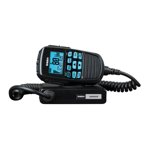
Uniden UH8060S User manual

Uniden

Uniden UH8060S User manual

Uniden GRANT XL User manual

Uniden

Uniden GRANT XL User manual

Uniden UH835S User manual

Uniden

Uniden UH835S User manual

Uniden BearTracker 885 User manual

Uniden

Uniden BearTracker 885 User manual

Uniden XTRAK40 User manual

Uniden

Uniden XTRAK40 User manual

Uniden BearCat PC78XL+ User manual

Uniden

Uniden BearCat PC78XL+ User manual

Uniden UH8050S User manual

Uniden

Uniden UH8050S User manual

Uniden UH9000S User manual

Uniden

Uniden UH9000S User manual

Uniden UH200 Series User manual

Uniden

Uniden UH200 Series User manual

Uniden SPH 51DT User manual

Uniden

Uniden SPH 51DT User manual

Uniden SMH250D User manual

Uniden

Uniden SMH250D User manual

Uniden UH8055S User manual

Uniden

Uniden UH8055S User manual

Uniden UH9000 User manual

Uniden

Uniden UH9000 User manual

Uniden UH037SX-2 User manual

Uniden

Uniden UH037SX-2 User manual

Uniden UH5060VP User manual

Uniden

Uniden UH5060VP User manual

Uniden MHS115 User manual

Uniden

Uniden MHS115 User manual

Uniden Jackson UT-547C/D User manual

Uniden

Uniden Jackson UT-547C/D User manual

Uniden DSC Series User manual

Uniden

Uniden DSC Series User manual

Uniden UH076 User manual

Uniden

Uniden UH076 User manual

Uniden UH7700NB User manual

Uniden

Uniden UH7700NB User manual

Uniden UH5040R User manual

Uniden

Uniden UH5040R User manual

Uniden UH8060NB User manual

Uniden

Uniden UH8060NB User manual

Uniden SMU250KTS User manual

Uniden

Uniden SMU250KTS User manual

Uniden UH9080 User manual

Uniden

Uniden UH9080 User manual

Popular Transceiver manuals by other brands

Nokia NHM-1 Series Software instructions

Nokia

Nokia NHM-1 Series Software instructions

Digiflex RF120 Installer's reference guide

Digiflex

Digiflex RF120 Installer's reference guide

AeroComm AC5124 user manual

AeroComm

AeroComm AC5124 user manual

Redifon GR345D instruction manual

Redifon

Redifon GR345D instruction manual

Kenwood TH-75A Service manual

Kenwood

Kenwood TH-75A Service manual

Kenwood ProTalk NX-P500 user guide

Kenwood

Kenwood ProTalk NX-P500 user guide

Standard Horizon HX471S owner's manual

Standard Horizon

Standard Horizon HX471S owner's manual

Kenwood TK-2107 Service manual

Kenwood

Kenwood TK-2107 Service manual

XIEGU G106 Operation manual

XIEGU

XIEGU G106 Operation manual

Utilicom LongRanger 2050 Operator's manual

Utilicom

Utilicom LongRanger 2050 Operator's manual

Siemens PSO 4000 Quick reference guide

Siemens

Siemens PSO 4000 Quick reference guide

PNI PMR R16 user manual

PNI

PNI PMR R16 user manual

Russound BSK-1 manual

Russound

Russound BSK-1 manual

Ranger SS-3900EGHP manual

Ranger

Ranger SS-3900EGHP manual

AMX SVSI NMX-ATC-N4321 quick start guide

AMX

AMX SVSI NMX-ATC-N4321 quick start guide

Kenwood TS-570D, TS-570S Adjustment guide

Kenwood

Kenwood TS-570D, TS-570S Adjustment guide

AeroComm CL4424 user manual

AeroComm

AeroComm CL4424 user manual

Swan Electronics 250 Operation and maintenance

Swan Electronics

Swan Electronics 250 Operation and maintenance

manuals.online logo
manuals.online logoBrands
  • About & Mission
  • Contact us
  • Privacy Policy
  • Terms and Conditions

Copyright 2025 Manuals.Online. All Rights Reserved.