Hobo RX3000 Series User manual
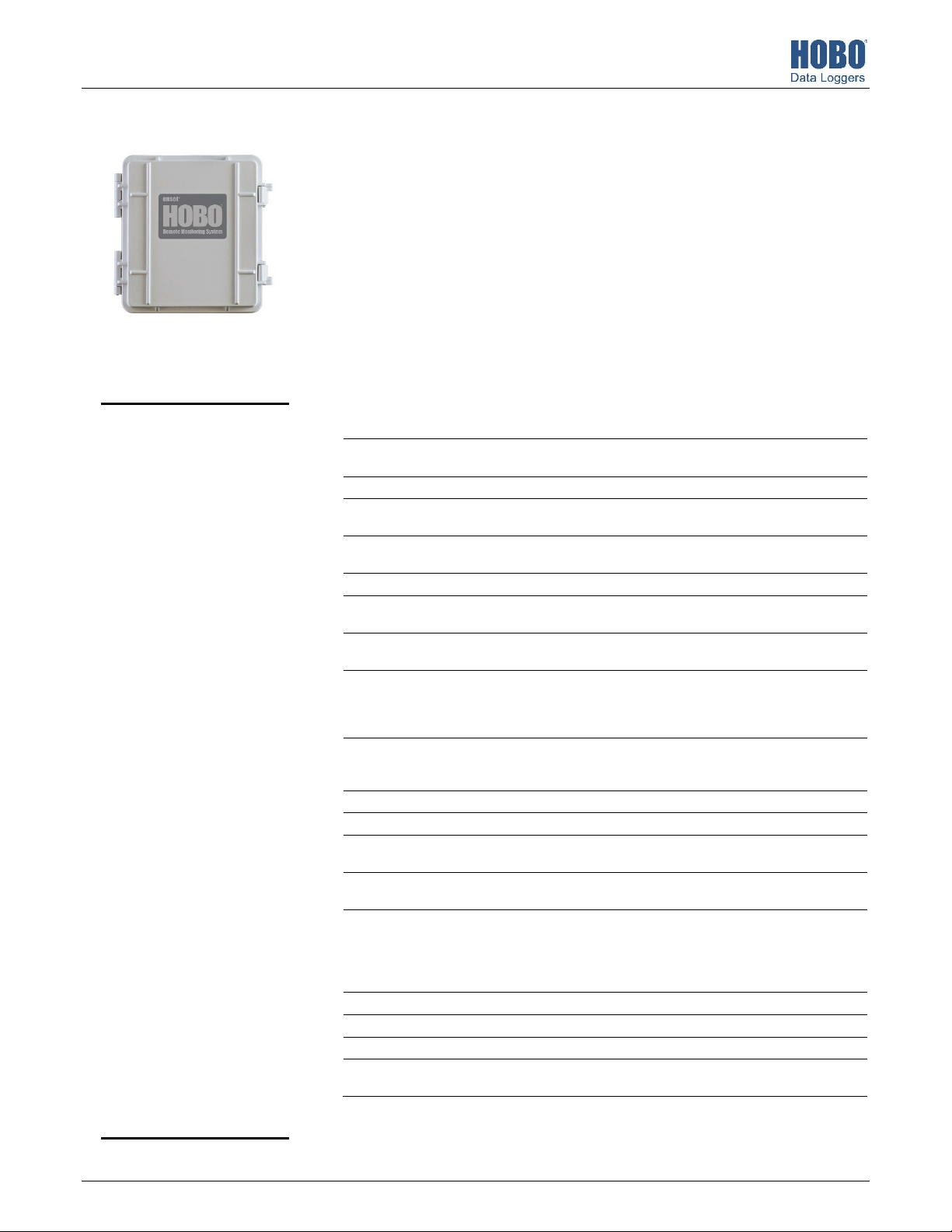
HOBO® RX3000 Remote Monitoring Station Manual
18255-L
The HOBO RX3000 Remote Monitoring Station provides continuous logging for a broad range of
energy and weather monitoring applications with up to ten smart sensors, optional analog sensor
and relay modules, and wireless sensor motes. Data from the RX3000 station is transferred at
regular connection intervals to HOBOlink® web-based software where you can check the latest
conditions, view graphs, configure sensors and alarms, set up a dashboard, download your data,
or schedule data delivery via email or FTP. Inside its weatherproof enclosure, this durable station
has a built-in LCD screen to check the current system configuration and status, start and stop
logging, add and remove smart sensors, and connect to HOBOlink on demand. Up to three
individual relays can be activated on the optional relay module while the optional analog module
has four analog inputs that support excitation power, scaling, and statistics measurements. An
optional RXW Manager module is also available for the station to set up the HOBOnet Wireless
Sensor Network, which can support up to 50 motes. All three easy-to-install modules can be
configured with HOBOlink.
Specifications
Station
Operating Range -40° to 60°C (-40° to 140°F); no remote communications for battery
voltage less than 3.9 V DC
Smart Sensor Connectors 10
Smart Sensor Network Cable
Length
100 m (328 ft) maximum
Smart Sensor Data Channels Maximum of 15 (some smart sensors use more than one data
channel; see sensor manual for details)
Module Slots 2
Logging Rate 1 second (RX3001 and RX3002) or 1 minute (RX3003 and RX3004) to
18 hours
Time Accuracy ±8 seconds per month in 0° to 40°C (32°F to 104°F) range;
±30 seconds per month in -40° to 60°C (-40° to 140°F) range
Battery Type/Power Source 4 Volt, 10 AHr, rechargeable sealed lead-acid; external power
required using one of these options: AC power adapter (AC-U30),
solar panel (SOLAR-xW), or external power source 5 V DC to 17 V DC
with external DC power cable (CABLE-RX-PWR)
Rechargeable Battery
Service Life
Typical 3–5 years when operated in the temperature range -20° to
40°C (-4°F to 104°F); operation outside this range will reduce the
battery service life
Memory 32 MB, 2 million measurements, continuous logging
Alarm Notification Latency Logging interval plus 2–4 minutes, typical
Enclosure Access Hinged door secured by two latches with eyelets for use with user-
supplied padlocks
LCD LCD is visible from 0° to 50°C (32° to 122°F); the LCD may react
slowly or go blank in temperatures outside this range
Materials Outer enclosure: Polycarbonate/PBT blend with stainless steel hinge
pins and brass inserts; Inner enclosure: Polycarbonate; Gaskets:
Silicone rubber; Cable channel: EPDM rubber; Cable opening cover:
Aluminum with ABS plastic thumb screws; U-Bolts: Steel with zinc
dichromate finish
Size 18.6 x 18.1 x 11.8 cm (7.3 x 7.1 x 4.7 in.); see diagrams on next page
Weight 2.2 kg (4.85 lb)
Mounting 3.8 cm (1.5 inch) mast or wall mount
Environmental Rating Weatherproof enclosure, NEMA 4X (requires proper installation of
cable channel system)
HOBO RX3000 Remote
Monitoring Station
Models: RX3001-00-01 Ethernet
RX3002-00-01 Wi-Fi
RX3003-00-01 Cellular
RX3004-00-01 Cellular 4G
Included Items:
• Two plates for cable access
openings with eight
thumbscrews and one wrench
• Two rubber cable channels
• Rubber plugs
• Grease packet
• Two mounting plates with
four screws
• Grounding wire
• Two U-bolts
Required Items:
• HOBOlink
• HOBOware® 3.7.2 or later
with USB cable for RX3002 Wi-
Fi models (optional for
RX3001, RX3003, and RX3004
models)
• AC adapter (AC-U30) or solar
panel (SOLAR-xW)
Optional Items:
• Smart sensors
• Analog sensor module
(RXMOD-A1)
• Relay module (RXMOD-R1)
• RXW Manager (RXMOD-RXW-
xxx) and RXW motes
• External DC power cable
(CABLE-RX-PWR)
• Tripod kit (M-TPA or M-TPB)
• Guy wire kit (M-GWA)
• 1/2 inch stake kit (M-SKA)
• Grounding kit (M-GKA),
required if using wind speed
or wind direction smart sensor
www.GlobalTestSupply.com
Find Quality Products Online at: sales@GlobalTestSupply.com

HOBO RX3000 Remote Monitoring Station Manual
2
Specifications (continued)
The CE Marking identifies this product as complying with all relevant
directives in the European Union (EU)
See last page
RX3002: FCC ID R68XPICOW, IC ID 3867A-XPICOW
RX3003: FCC ID QIPEHS6, IC ID 7830A-EHS6; approved for use in
Taiwan and Japan
RX3004: FCC ID QIPPLS62-W, IC ID:7830A-PLS62W
Ethernet (RX3001)
Connector One RJ45/100BaseT
W
i-Fi (RX3002)
Network Standards IEEE 802.11b/g/n
Frequency Range 2.412–2.484 GHz
Antenna Connector 1, no diversity supported
Data Rates 1, 2, 5.5, 11 Mbps (802.11b); 6, 9, 12, 18, 24, 36, 48, 54 Mbps (802.11g
802.11n, HT20 MCS0 (6.5 Mbps) to HT20 MC87 (65 Mbps)
Number of Selectable Radio
Subchannels
Up to 14 channels; profiles available will include USA, France, Japan,
Spain, Canada, and “Other” (multiple countries)
Radio Modulations OFDM, DSSS, DBPSK, DQPSK, CCK, 16QAM, 64QAM
Security WEP 64/128, WPA-PSK, AES end-to-end encryption
Maximum Receive Level -10 dBm (with PER <8%)
Receiver Sensitivity -72 dBM for 54 Mbps, -87 dBm for 11 Mbps, -89 dBm for 5.5 Mbps,
-90 dBm for 2.0 Mbps, -92 dBm for 1.0 Mbps
C
ellular (RX3003 and RX3004)
Wireless Radio RX3003:
GSM/GPRS/EDGE: Quad band 850/900/1800/1900 MHz,
UMTS/HSPA+: Five band 800/850/900/1900/2100 MHz
RX3004:
GSM/GPRS/EDGE: Quad band 850/900/1800/1900 MHz
UMTS/HSPA+: Seven band 800/850/900/1800/1900/2100 MHz
LTE: Twelve Band 700/800/850/900/1800/1900/2100/2600 MHz
Antenna RX3003: Penta band
RX3004: 4G LTE
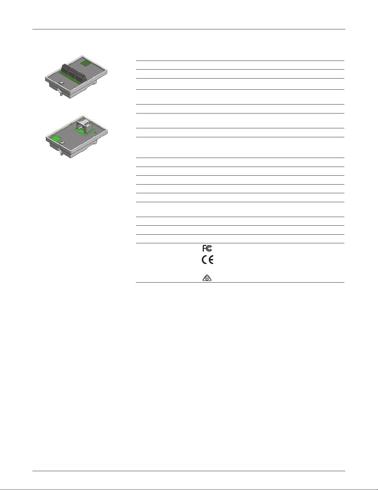
Optional Analog Sensor Module (RXMOD-A1)
Input Channels Four, single-ended, in addition to smart sensor data channels
Measurement Range and
Accuracy
0–25.6 mA DC, ±5 µA ± 0.15% of reading
0–2.5 V DC, ±0.25 mV ±0.2% of reading
0–5 V DC, ±0.25 mV ±0.2% of reading
0–10 V DC, ±0.3 mV ±0.2% of reading
0–20 V DC, ±0.6 mV ±0.2% of reading
0–33 V DC, ±1.20 mV ±0.2% of reading
Resolution 15 bits
Field Wiring Two- or three-wire via screw terminals, 16–24 AWG
Minimum/Maximum Input
Voltage
0/33 V DC
Minimum/Maximum Input
Current
0/25.6 mA
Minimum Source Impedance
for Current Measurement
20 KΩ
Excitation Voltage 12 V DC ±5% at 200 mA maximum per module
Alarm Output Relays Each relay contact closure can be configured as normally open,
normally closed, or pulsed for one second
Voltage 30 V max
Dimensions
Analog Sensor Module (RXMOD-A1)
11.8 cm
4.7 in.
18.6 cm
(
7.3 in.
)
18.1 cm
(7.1 in.)
www.GlobalTestSupply.com
Find Quality Products Online at: sales@GlobalTestSupply.com
HOBO RX3000 Remote Monitoring Station Manual
3
Specifications (continued)
Optional Relay Module (RXMOD-R1)
Relays Three independent relays
Current 1 Amp max
Optional RXW Manager Module (RXMOD-RXW-xxx)
O
perating Temperature
Range
-25° to 60°C (-13° to 140°F)
Radio Power 12.6 mW (+11 dBm) non-adjustable
Transmission Range At least 304.8 m (1,000 ft) line of sight at 1.8 m (6 ft) from the ground,
457.2 m (1,500 ft) typical
Wireless Data Standard IEEE 802.15.4
Radio Operating Frequencies RXMOD-RXW-900: 904–924 MHz
RXMOD-RXW-868: 866.5 MHz
RXMOD-RXW-922: 916–924 MHz
Modulation Employed OQPSK (Offset Quadrature Phase Shift Keying)
Data Rate Up to 250 kbps, non-adjustable
Duty Cycle <1%
Maximum Number of Motes 50 motes per one RX Wireless Sensor Network
Power Source Powered by the RX3000 station
Dimensions Mote: 16.2 x 8.59 x 4.14 cm (6.38 x 3.38 x 1.63 inches)
Cable length: 2 m (6.56 ft)
Weight Mote: 159 g (5.62 oz)
Materials Mote: PCPBT, silicone rubber seal
Environmental Rating Mote: IP67
C
ompliance Marks RXMOD-RXW-900: See last page
RXMOD-RXW-868: The CE Marking identifies this product as
complying with all relevant directives in the European Union
(EU).
RXMOD-RXW-922: See last page
Table of Contents
Device Components and Operation ............................................... 4
LCD Operation ................................................................................ 5
Setting up the Station .................................................................... 7
a. Log in to HOBOlink. ............................................................. 7
b. Register the station. ............................................................ 7
3. Install optional modules or user-supplied SIM. ................... 7
4. Plug in the battery and charging device. ............................. 7
5. Check and configure device communications. .................... 8
6. Plug in and search for any smart sensors. ........................... 9
7. Add any wireless sensor motes. .......................................... 9
8. Connect analog sensors or relay devices. .......................... 10
9. Connect to HOBOlink. ....................................................... 10
10. Configure the station in HOBOlink. ................................... 11
11. Start logging. ..................................................................... 13
Viewing Data in HOBOlink ............................................................ 14
Setting System and Sensor Alarms ............................................... 14
System Alarms ......................................................................... 14
Sensor Alarms .......................................................................... 15
Starting and Stopping Logging ...................................................... 15
Adding or Removing Smart Sensors ............................................. 16
Adding or Removing Modules ...................................................... 16
Adding or Removing Motes ......................................................... 17
Managing Connections to HOBOlink ............................................ 18
Checking Latest Conditions with HOBOware ............................... 18
Deploying and Mounting the Station ........................................... 18
Deployment Guidelines ........................................................... 18
Installing the Grounding Wire ................................................. 20
Mounting the Station .............................................................. 20
Installing the Weatherproof Rubber Cable Channel and Covers20
Care and Maintenance ................................................................. 21
Troubleshooting........................................................................... 21
Battery Information ..................................................................... 22
Relay Module (RXMOD-R1)
RXW Manager Module
(RXMOD-RXW-xxx)
www.GlobalTestSupply.com
Find Quality Products Online at: sales@GlobalTestSupply.com
HOBO RX3000 Remote Monitoring Station Manual
4
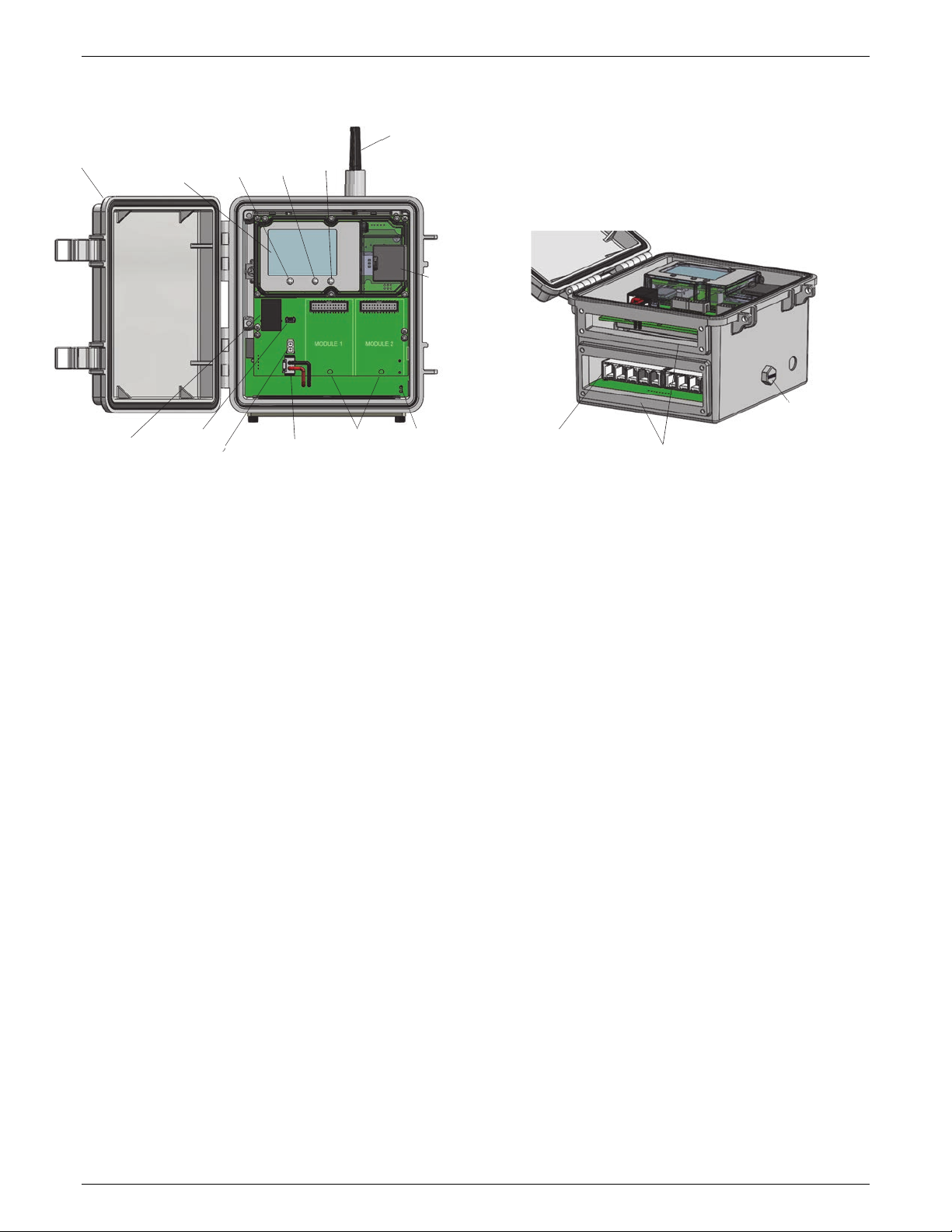
Device Components and Operation
Station Door: This is the protective, hinged door covering the
LCD and electronics. The station serial number and device key
needed for HOBOlink registration are located on the inside of
the door.
LCD Screen: This shows details about system, module, and
sensor operation (see LCD Operation).
Select Button: Use this button to cycle through information
about the smart sensors and optional modules (see LCD
Operation).
Start/Stop Button: Use this button to start and stop logging or
clear a fault code (see LCD Operation).
Connect/Search Button: Use this button to connect to
HOBOlink or search for new smart sensors (see LCD Operation).
Antenna: This is the external radio antenna for cellular
communication in the RX3003 model. The RX3002 and RX3004
models use an internal antenna.
SIM Card/Micro SIM Card: A SIM card is installed in the RX3003
model or a micro SIM card is installed in the RX3004 model to
enable cellular communications.
Grounding Wire Port: Use this port to connect a grounding wire
(see Deploying and Mounting the Station).
Module Slots: These are two slots for installing optional analog
sensor, relay, or RXW Manager modules (see Setting up the
Station).
Battery Port: Use this port to plug in the internal battery cable
(see Setting up the Station and Battery Information).
Charging Port: Use this port to plug in an AC adapter, solar
panel, or external power source to keep the battery charged
(see Setting up the Station and Battery Information).
USB Port: Use this port to connect the station to the computer
via USB cable as needed for HOBOware.
Ethernet Connector: Use this port to connect an Ethernet RJ45
cable for the RX3001 model (see Setting up the Station).
Smart Sensor Connectors: Use these input jacks to connect up
to 10 smart sensors (see Setting up the Station). The station can
support up to 15 smart sensor data channels; some smart
sensors have more than one data channel.
Cable Access Openings: These are the two openings for
connecting cables and wires to the station (see Setting up the
Station). Install the cover plates and rubber cable channels in
these openings to create a weatherproof seal (see Deploying
and Mounting the Station).
Vent. This vent allows pressure to equalize inside the station
while keeping water out. Note that the pressure inside the
station does not match the outside air pressure exactly.
Therefore, a barometric pressure sensor deployed within the
case cannot measure the true atmospheric pressure unless it
has its own unrestricted vent to the outside.
Battery Port
Smart Sensor
Connectors Cable Access Openings
Vent
SIM Card
(RX3003) or
Micro SIM Card
(RX3004)
LCD Screen
Ethernet
Connector
(
RX3001
)
Charging Port
USB Port Module Slots
Station Door
Antenna
(RX3003)
Grounding
Wire Port
Connect/
Search
Button
Start/
Stop
Button
Select
Button
www.GlobalTestSupply.com
Find Quality Products Online at: sales@GlobalTestSupply.com

HOBO RX3000 Remote Monitoring Station Manual
5
LCD Operation
This example shows all symbols illuminated on the LCD screen with an overview of what each section of the LCD represents. Refer to the
table below for details about each section and associated symbols.
System Status
This part of the LCD shows the overall system status.
or
When the station is powered up, “Initializing System” flashes in the upper left part of the LCD. After initialization is
complete, “System” remains illuminated and one of these symbols will appear:
indicates the system is ok.
indicates there is a problem with the system; check the Device Information panel on your station page in HOBOlink.
Connection Status
This part of the LCD shows the communication method used for connecting to HOBOlink and the system connection
status.
This indicates the station is connected via a USB cable.
This indicates the station is using Ethernet to connect to HOBOlink. This will blink while connecting to HOBOlink.
This indicates the station is using Wi-Fi to connect to HOBOlink. This also shows the strength of the wireless signal; the
more bars there are, the stronger the signal. This will blink while connecting to HOBOlink.
This indicates the station is using a cellular network to connect to HOBOlink. This also shows the strength of the cellular
signal; the more bars there are, the stronger the signal. This will blink while connecting to HOBOlink.
or
When the station is attempting to connect or is currently connected to HOBOlink, “Connection” flashes on the LCD. After
the connection is complete, “Last Connection” remains illuminated and one of these symbols will appear:
indicates the last connection to HOBOlink was ok.
indicates there was a problem with the last connection; check the Connections log in HOBOlink.
Smart Sensor and
Module Status
This part of the LCD shows the status of the smart sensors and any optional modules installed. Module 1 is installed in the
left slot and Module 2 in the right slot.
One of the following symbols will also appear next to smart sensors or a module (if applicable):
indicates the smart sensor or module is ok.
indicates there is a problem with the smart sensor or module; check your device page in HOBOlink.
indicates a sensor alarm has tripped and will flash on the LCD until the alarm is cleared; check the Alarms log in
HOBOlink.
Logging Status
This part of the LCD indicates whether the station is currently logging.
or
“Stopped” indicates the station is not currently logging while “Logging” indicates it is currently logging. Press the
Start/Stop button to start or stop logging as desired. Note that “Logging” will blink until the first data point is logged after
the Start button is pressed.
Battery and
Memory Status
This part of the LCD shows the current battery level and memory.
or
The battery indicator shows the approximate battery power remaining. In this example, the battery is fully charged. The
lightning bolt will appear when an AC adapter, solar panel, or external power source is plugged into the station. “Charging”
will flash while the battery is being charged.
When the station is logging, it will record data indefinitely, with newest data overwriting the oldest data until the station is
stopped. This continuous logging is represented by the arrow in this symbol.
System Status
Connection Status
Smart Sensor and
Module Status
Logging Status
Battery and Memory Status
Channel and Device
Information
Button Symbols
www.GlobalTestSupply.com
Find Quality Products Online at: sales@GlobalTestSupply.com

HOBO RX3000 Remote Monitoring Station Manual
6
Channel and
Device
Information
This part of the LCD shows the number of channels and other information about each module. It also shows general device
information. Press the Select button to scroll through four screens: the main screen, smart sensors screen, Module 1, and
Module 2 screens.
or
Main Screen
When viewing the main LCD screen, the total number of
channels in use by the system is displayed. This is a
combination of smart sensor channels and enabled
sensor channels. For example, if there are 5 smart sensor
channels and 3 analog sensor channels, then 8 channels
are shown on the main screen, as in the following
example.
Smart Sensors Screen
When viewing the smart sensors screen, the number of smart
sensor channels is displayed. Note that some smart sensors
have more than one channel associated with them so the
number of channels may not match the number of physical
smart sensors. In this example, there are 5 smart sensor
channels.
Module 1
When viewing the Module 1 or Module 2 screen,
information about that particular module is displayed. If
an analog sensor module is installed, the number of
enabled analog sensors is displayed in the channels count
(three sensors in this example). If an RXW Manager
module is installed, the channel count represents all
measurement channels plus a battery channel for each
mote in the RX Wireless Sensor Network. For example,
one temp/RH wireless sensor has a channel count of
three as shown below: two for temperature and RH and
one for the mote battery.
Module 2
When a relay module is installed, the state of each relay is
shown on the module screen. In this example, a relay module
is installed in the Module 2 slot so this shows whether each
relay is open “o” or closed “c”. In this example, the first and
third relays are open, and the second one is closed.
This will blink in the lower right part of the LCD when a firmware update is underway. It will display which module or
element is being updated.
This is a numerical code that appears when a system fault has occurred. You may need to provide this code to Onset
Technical Support. See Troubleshooting for details.
This is the version number of the station firmware. It only appears when powering up the device.
Button Symbols
Use the three buttons below the following symbols to operate the station. Press any of the three buttons to turn on the
LCD.
Press this button to cycle through status information about the smart sensors and two optional modules.
Press this button to start logging. This option is not available while the station is actively connected to HOBOlink.
Press this button to stop logging. This option is not available while the station is actively connected to HOBOlink.
Press this button to connect to HOBOlink. This option is only available on the main LCD screen. It is not available when
scrolling through smart sensor and module information with the Select button. In addition, this option is not available while
a connection is underway or active.
Press this Search button for the station to detect all currently installed smart sensors or to add motes to your RX Wireless
Sensor Network. As you add or remove smart sensors while the station is stopped, press the Select button and then the
Search button for the system to recognize your changes. This option is not available for smart sensors while the station is
logging. To add motes to the RX Wireless Sensor Network, press the Select button to switch to the module for the RXW
Manager and then press the Search button for the station to find the motes. The station can search for motes whether it is
logging or stopped.
Use this button to clear a fault code.
www.GlobalTestSupply.com
Find Quality Products Online at: sales@GlobalTestSupply.com

HOBO RX3000 Remote Monitoring Station Manual
7
Notes on LCD Operation:
• The LCD will turn off after 5 minutes of inactivity. Press
any button to turn the LCD back on.
• There can be a delay before the LCD updates. For
example, if you plug in an AC adapter, it may take a few
seconds before the lightning bolt icon appears on the
LCD. This delay is by design to preserve battery life.
Setting up the Station
Follow these steps to set up the station.
a. Log in to HOBOlink.
g in to an existing account
or create a new one. You’ll receive an email to activate the
new account.
b. Register the station.
In HOBOlink, click Devices and then click the Register a
Device link. Give the station a name and enter the serial
number and device key from the label inside the station
door.
3. Install optional modules or user-supplied SIM.
a. Make sure the station is powered down (unplug any
charging device and then disconnect the battery).
b. Insert the connector on the back of the module into the
receptacle in the left or right module slot. Add a second
module to the other slot if desired.
Tip: Install the analog module or RXW Manager module
on the left and the relay module on the right for easier
cable routing.
c. Using a Phillips-head screwdriver, tighten the screw at
the bottom of each module. In this example, an analog
module is installed in the Module 1 slot and a relay
module is installed in the Module 2 slot.
If you are installing an RXW Manager module, plug the
cable from the RXW Manager mote into the jack on the
module, making sure the cable is inserted through the
bottom of the station case. Do not reconnect the power on
the station until the mote is plugged in as shown.
WARNING: If you inadvertently install modules while the
power is on, you must disconnect and then reconnect the
battery and charging device to guarantee proper
operation.
Note: If you are using your own SIM card, follow the
instructions at h
4. Plug in the battery and charging device.
a. Plug in the battery cable.
b. Feed the AC adapter or solar panel cable through the
smaller of the two cable openings and plug it in. You can
also use an optional external DC power cable (CABLE-
RX-PWR) with your own powering device in place of the
AC adapter or solar panel.
Connect the battery cable here
Plug in an AC adapter
or solar panel here
Insert the connectors
on the module here
Tighten the screw on installed modules
www.GlobalTestSupply.com
Find Quality Products Online at: sales@GlobalTestSupply.com

HOBO RX3000 Remote Monitoring Station Manual
8
c. Once the battery cable is plugged in, “Initializing
System” will flash on the LCD. A checkmark appears next
to “System” after the station initialization is complete.
5. Check and configure device communications.
For RX3003 and RX3004 cellular models:
After the station powers up in the previous step, it will
connect to HOBOlink automatically within two minutes. The
cellular icon and “Connection” will flash while the
connection is underway. Once the connection is complete, a
checkmark appears next to Last Connection. Note that the
entire initialization process may take several minutes; wait
until Last Connection and the checkmark appears before
continuing to step 6.
For RX3001 Ethernet models:
a. Plug in an Ethernet cable.
b. The station uses DHCP by default. If your network uses
DHCP, skip to step i.
If your network uses static IP addresses, connect the
station to the computer with the USB cable. (Consult
your Network Administrator if you are unsure whether
your network uses static IP addresses or for help with
the following steps).
c. In HOBOware, select Manage RX3000 from the Device
menu. (On a computer with Microsoft® Windows®, you
may see a warning that Windows Firewall has blocked
some features. Select Domain networks and click Allow
Access.)
d. In the RX3000 Manager, click the Actions button.
e. Deselect the Use DHCP checkbox.
f. Enter the IP Address, Subnet Mask, Gateway, and DNS
Server. Consult your Network Administrator for the
appropriate addresses to complete these fields.
g. Click Save in the RX3000 Manager. Click Done and then
close the RX3000 Manager.
h. Disconnect the USB cable.
i. Press the Connect button on the station (the cloud
should be visible on the LCD screen) to connect to
HOBOlink. The Ethernet icon and “Connection” will flash
while the connection is underway. Once the connection is
complete, a checkmark appears next to Last Connection.
Wait for the checkmark and then continue to step 6.
For RX3002 Wi-Fi models:
a. Connect the station to the computer with the USB
cable.
b. In HOBOware, select Manage RX3000 from the Device
menu. (On a computer with Microsoft® Windows®, you
may see a warning that Windows Firewall has blocked
some features. Select Domain networks and click Allow
Access.)
c. In the RX3000 Manager, click the Actions button.
d. Enter the Security information for your Wi-Fi network.
Type the Network Name, select the Security Type, and
type the Security Key. Select the Hide characters
checkbox to hide any characters typed into the Security
Key field. Consult your Network Administrator or
wireless router documentation for help with
determining your network security type.
“Initializing
System”
flashes when
the battery
cable is first
plugged in
A checkmark
appears next to
Last Connection
after connecting
to HOBOlink
Plug in an Ethernet cable here
A checkmark
appears next to
Last Connection
after connecting
to HOBOlink
www.GlobalTestSupply.com
Find Quality Products Online at: sales@GlobalTestSupply.com

HOBO RX3000 Remote Monitoring Station Manual
9
e. The station uses DHCP by default. If your network uses
DHCP, skip this step.
If your network uses static IP addresses, deselect the
Use DHCP checkbox. Enter the IP Address, Subnet Mask,
Gateway, and DNS Server. Consult your Network
Administrator if you are unsure whether your network
uses static IP addresses or for the appropriate addresses
to enter in this fields.
f. Click Save in the RX3000 Manager. Click Done and then
close the RX3000 Manager.
g. Disconnect the USB cable.
h. Press the Connect button on the station (the cloud
should be visible on the LCD screen) to connect to
HOBOlink. The Wi-Fi icon and “Connection” will flash
while the connection is underway. Once the connection
is complete, a checkmark appears next to Last
Connection. Wait for the checkmark and then continue
to step 6.
6. Plug in and search for any smart sensors.
Important: If this RX3000 station is a replacement for an
existing U30 station, it is imperative that you power down
the U30 station being replaced (disconnect the battery
and AC adapter or solar panel) before you remove the
smart sensors and connect them to the RX3000. Do not
repower the U30 station or allow it to connect to
HOBOlink again unless at least one different smart sensor
is connected to the U30 station first.
a. Feed the smart sensor cable for one smart sensor
through the larger of the two cable openings and plug it
into one of the 10 smart sensor connectors. Repeat for
any additional smart sensors.
b. Press the Select button to view the smart sensors on the
LCD and then press the Search button (the magnifying
glass icon should be visible as in the following example).
The station will search for all connected smart sensors
and show the number of channels after a few seconds.
Note that some smart sensors have more than one
channel associated with them so the number of
channels may not match the physical number of smart
sensors connected (for example the temperature/RH
smart sensor has two channels: one for temperature
and one for RH).
7. Add any wireless sensor motes.
Important: Keep the mote(s) near the RX3000 station while
completing these steps.
a. Press select to switch to the module where the RXW
Manager is installed (Module 1 or Module 2) and then
press the Search button to wait for motes to join the
network.
b. Install the rechargeable batteries in the mote and press
the button on the mote for 3 seconds.
Press the Select button to view
the smart sensor screen
Press the Search button for the station
to find all connected smart sensors
Plug in smart sensors here
A checkmark
appears next to
Last Connection
after connecting
to HOBOlink
Press the Search button for the
station to search for motes to join
Press the Select button to switch to the
module with RXW Manager installed
Press this button for 3 seconds
www.GlobalTestSupply.com
Find Quality Products Online at: sales@GlobalTestSupply.com
HOBO RX3000 Remote Monitoring Station Manual
10
c. Watch the mote LCD during the process of joining the
network.
Note: If the mote cannot find the network or has
trouble remaining connected during this process, make
sure the mote is in a vertical, upright position and
within range of the station.
Repeat these steps to add other motes. Press the
Search button on the station when finished adding
motes.
8. Connect analog sensors or relay devices.
If you are using the optional analog sensor module or relay
module, follow the steps in this section to connect the
sensors or devices. Be sure to feed any cables or wires
through the smaller cable access opening shown below.
Important: If you will be installing the weatherproof rubber
cable channel in the cable access opening as described in
Deploying and Mounting the Station, the cable diameter for
analog sensors or relay devices must be 4.0 mm (0.156 in.) to fit
through one of the five smaller holes or 6.4 mm (0.25 in.) to fit
through one of the five larger holes. If the cable diameter is too
small, build up the diameter using heat shrink. If the cable is
too big, splice on another cable with a smaller diameter to fit
through the hole.
To connect analog sensors:
You can connect a two- or three-wire sensor or transducer
to one of the four terminals in the analog module.
a. Loosen the screw for each pin on the screw terminal.
b. Feed the wire through the smaller of the two cable
access openings.
c. Insert the appropriate wire into the screw terminal (see
the pinout table below). The wire should be trimmed to
expose 0.25 inches ±0.04 inches of bare wire.
d. Tighten the screw.
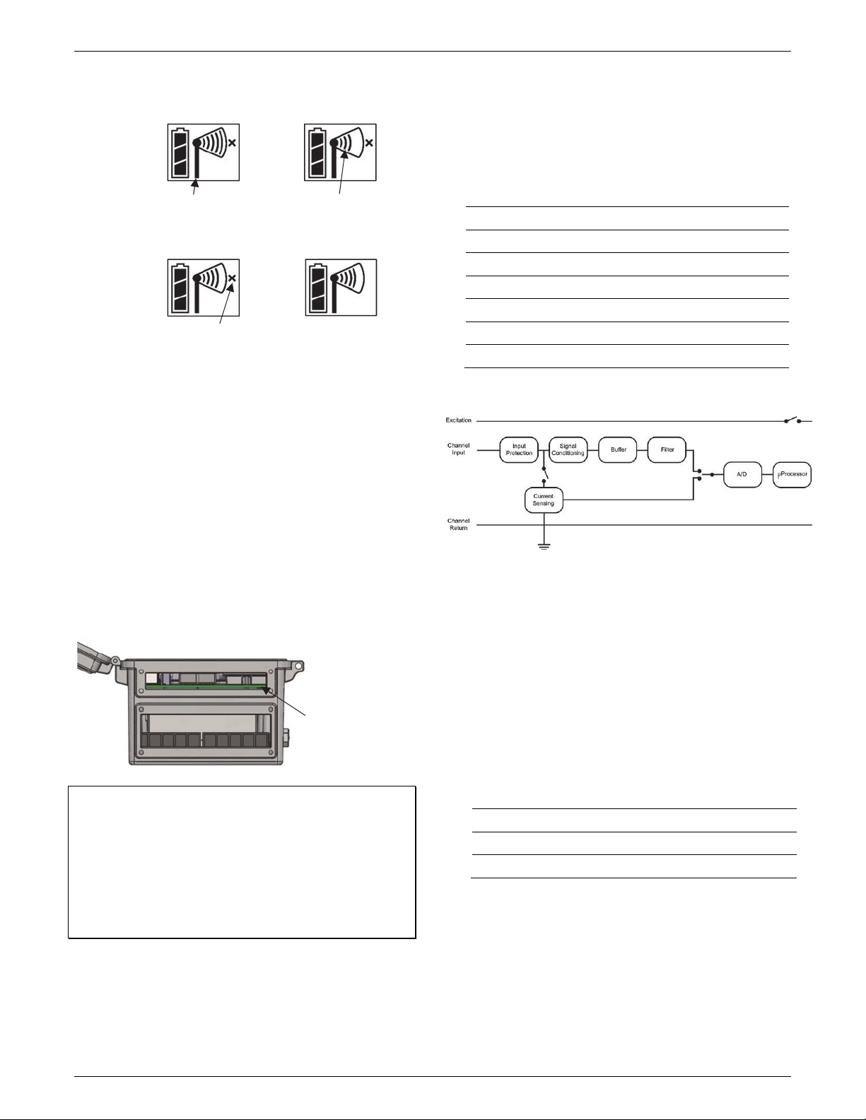
Analog Module Pinout Table
J1
Pin # Pin Description
J2
Pin # Pin Description
1 CH1 SIGNAL 1 CH3 SIGNAL
2 CH1 GND 2 CH3 GND
3 +12V Excitation 3 +12V Excitation
4 GND (EX. RTN) 4 GND (EX. RTN)
5 CH2 SIGNAL 5 CH4 SIGNAL
6 CH2 GND 6 CH4 GND
7 SHIELD 7 SHIELD
Note: All four input channels share the same common ground.
Analog Module Functional Diagram
To connect relay devices:
You can connect up to three devices to the relay module.
The relays are only for low power switching. To switch to
higher power, use an appropriately rated relay and use the
station relay to switch the external relay on or off.
a. Loosen the screw for each pin on the screw terminal.
b. Feed the wire through the smaller of the two cable
access openings.
c. Insert the appropriate wire into the screw terminal (pins
1 and 2 are interchangeable, pin 3 is optional; see the
pinout table).
d. Tighten the screw.
Relay Module Pinout Table
RELAY-1
Pin Desc.
RELAY-2
Pin Desc.
RELAY-3
Pin Desc.
1 Relay 1 Relay 1 Relay
2 Relay 2 Relay 2 Relay
3 Shield 3 Shield 3 Shield
9. Connect to HOBOlink.
Use the Select button to return to the main LCD screen that
shows all sensors and modules and then press the Connect
button (the cloud icon should be visible as shown in the
following example). This is necessary for HOBOlink to
identify the newly added sensors (it does not start logging;
this will be done later in this procedure). Note that analog
sensors will not be listed in the channels count on the LCD
until they are configured in HOBOlink in the next step.
Feed analog sensor
and relay cables
through this opening
to connect them to
the optional modules
This signal strength icon
blinks while searching for
a network.
Once a network is found,
the icon will stop flashing
and the bars will cycle from
left to right.
c. d.
This network connection “x”
icon blinks while the mote
completes the registration
process, which may take up
to five minutes.
Once the mote has finished
joining the network, the “x”
icon is removed and the
channel count on the station
LCD increases by the number
of measurement channels for
the mote plus the battery.
a. b.
www.GlobalTestSupply.com
Find Quality Products Online at: sales@GlobalTestSupply.com
HOBO RX3000 Remote Monitoring Station Manual
11
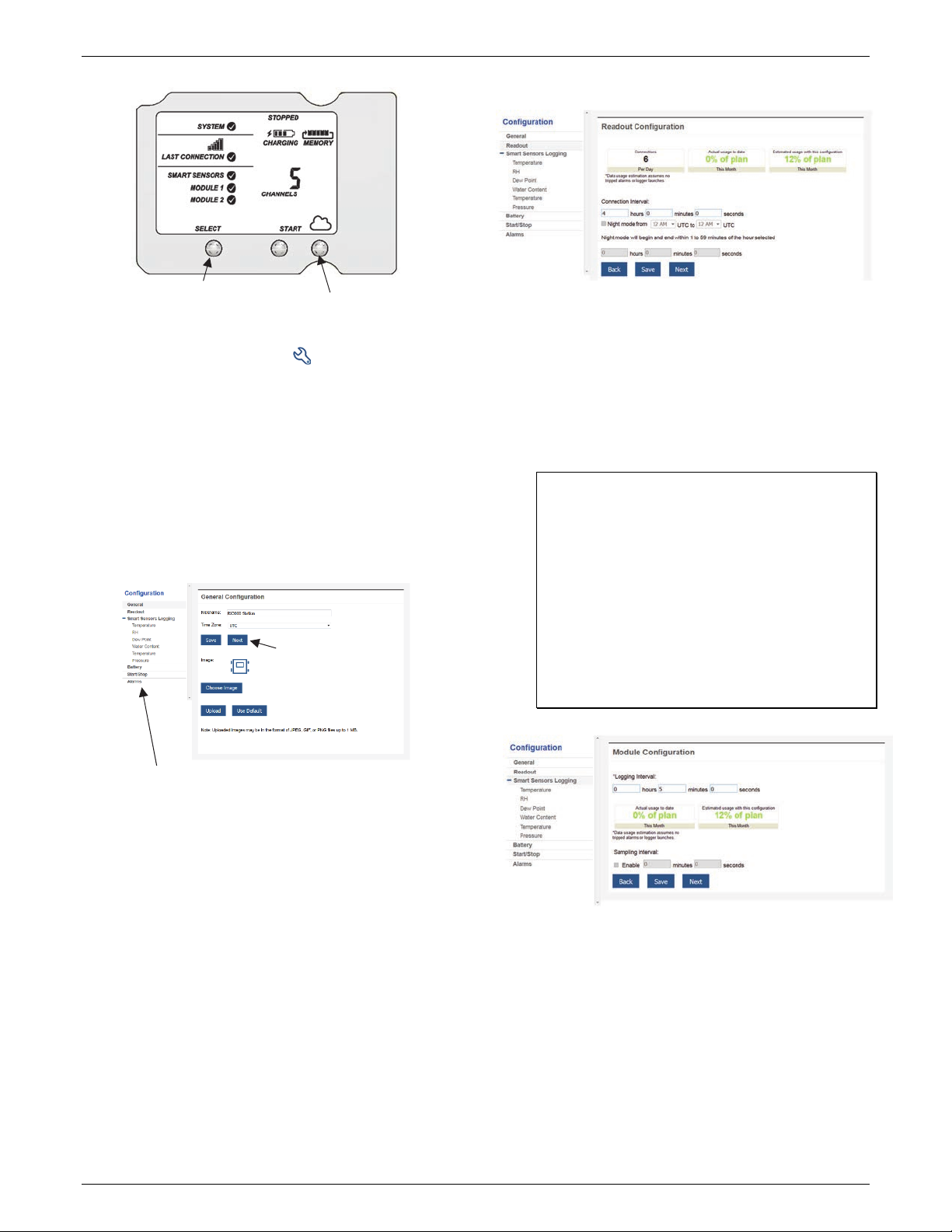
10. Configure the station in HOBOlink.
Go to Devices > List and click the icon next to your
station. Use the configuration screens in HOBOlink to finish
setting up the station, starting with General Configuration
(the nickname, time zone, and image for the station). Use
the Next button to move from one configuration screen to
the next or use the left menu to select a specific item to
configure. Follow the steps in the next subsections to
configure the readout settings, smart sensors, wireless
sensors, and optional modules. Any changes you make will
take effect the next time the station connects to HOBOlink.
Note: Click Save or Next in any screen to save your changes.
You will lose any changes made if you click Back without
clicking Next or Save first.
Readout Configuration
a. Set the connection interval, which is how often the
station will connect to HOBOlink. For the RX3003 and
R3004 cellular models, the minimum connection
interval depends on your communication plan.
b. If you wish to set up a second connection interval, select
the “Night mode” checkbox. Select when night mode
should begin and end and then enter the connection
interval you want to use during that part of the day.
(The night mode schedule can take effect any time
during the day; it does not have to be at night.) Use this
option to save data in your communications plan (if
applicable) or to conserve battery power at night when
solar charging is unavailable. You can view current plan
usage in the Device Information section on your
station’s page in HOBOlink.
c. Click Save or click Next.
Smart Sensors Logging and Configuration
You can configure both the global settings that affect all smart
sensors (logging interval and sampling interval) and the settings
for each smart sensor (labels, graphs, and scaling).
a. Click Smart Sensors Logging from the menu on the left.
b. Select the logging interval. This will be used by all
configured smart sensors.
c. Enable the sampling interval and enter the rate to use in
minutes and seconds.
Tip: When a sampling interval is configured, the station
will take multiple measurements within a given logging
interval and then average them together to create a
single logged data point. This is only an option for the
following smart sensors that support measurement
averaging: temperature (S-TMB-M0xx), PAR (S-LIA-
M003), solar radiation (S-LIB-M003), barometric
pressure (S-BPA-CM10 and S-BPB-CM50), 4-20mA input
(S-CIA-CM14), 12-bit voltage input (S-VIA-CM14), and
FlexSmart TRMS module (S-FS-TRMSA-D). Disable the
sampling interval if none of your smart sensors support
measurement averaging to avoid unnecessary drain on
the battery power.
d. Click Save or click Next.
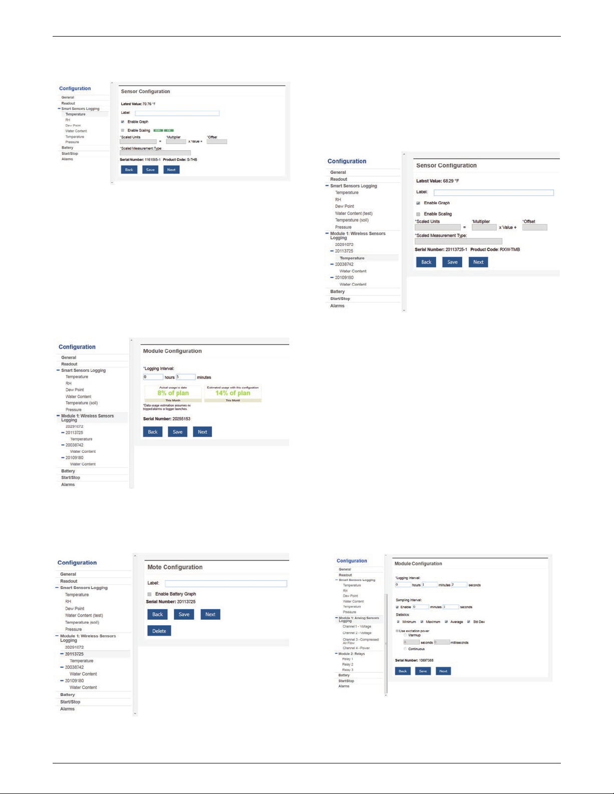
e. Click a smart sensor from the menu.
f. Type a label for the smart sensor (optional) and click to
enable or disable the graph (enabled by default).
g. To set up scaling for the smart sensor, click the Enable
Scaling checkbox and fill in the Scaled Units, Multiplier,
Offset, and Scaled Measurement Type fields.
Press the Connect button
Press the Select button to
return to the main LCD screen
Or, you can choose a specific item
to configure from this menu
Use the Next button to save changes and
move through each configuration screen
www.GlobalTestSupply.com
Find Quality Products Online at: sales@GlobalTestSupply.com
HOBO RX3000 Remote Monitoring Station Manual
12
h. Click Save. You can also click Next to move from one
smart sensor to the next.
i. Repeat steps e–h for any additional smart sensors you
need to configure.
Wireless Sensor Configuration
You can configure both the global settings for the RXW
Manager module that affect all sensor motes (logging
interval) and the settings for each individual mote (labels,
enabled graphs, and scaling).
a. Click Module <#>: Wireless Sensors Logging from the
menu on the left.
b. Select the logging interval to be used for all wireless
sensors, which can be different than the one used for
smart sensors and analog sensors (if applicable).
c. Click Save or Next.
d. Click one of the motes from the menu under Module <#>:
Wireless Sensors Logging as shown in the following
example. Click the serial number or name for the mote,
not the measurement type.
e. Type a label for the mote (optional) and click to enable
the battery graph for the mote if desired. The label will
also automatically be applied to any mote sensors
without a default label.
f. Click Save or click to Next to move to either the next
mote (if it was a repeater) or the sensor measurement
type for that mote.
g. Click one of the mote measurement types from menu
under Module <#>: Wireless Sensors Logging as shown
in the following example
h. Type a label for the measurement type (optional) and
click to enable or disable the graph (enabled by default).
i. To set up scaling for the wireless sensor, click the Enable
Scaling checkbox and fill in the Scaled Units, Multiplier,
Offset, and Scaled Measurement Type.
j. Click Save or click Next.
k. Repeat steps d–j for any additional motes you need to
configure for the module.
Analog Module and Sensor Configuration
You can configure both the global settings for the analog
module that affect all connected analog sensors (logging
interval, statistics, and excitation) and the settings for each
individual analog sensor (enabled logging and graphs,
labels, sensor type, and scaling).
a. Click Module <#>: Analog Sensors Logging from the
menu on the left.
b. Select the logging interval to be used for all analog
sensors, which can be different than the one used for
smart sensors and wireless sensors (if applicable).
c. Click the Enable checkbox under Sampling Interval if you
want to log statistics. Enter the sampling interval to be
used for calculating the statistics (must be a factor of
the logging interval). Select the statistics to be logged:
www.GlobalTestSupply.com
Find Quality Products Online at: sales@GlobalTestSupply.com

HOBO RX3000 Remote Monitoring Station Manual
13
minimum, maximum, average, and standard deviation.
The selected statistics will be calculated between each
logging interval at the sampling interval rate you select.
Each statistical value will then be logged at each logging
interval.
d. Enable “Use excitation power” if you want sensors to
use the 12 V DC excitation voltage provided by the
station. Select warmup and enter the seconds or
milliseconds (5 milliseconds to 120 seconds), or select
continuous. Note that the excitation power selected will
be used for all of the module’s configured sensors.
• With warmup, the station supplies excitation power,
12 V DC, for a brief period prior to each
measurement. This allows you to select the minimum
warm-up time needed to allow for sensor
stabilization while conserving battery power. For
example, if you specify a warm-up of one second and
set the logging interval for the module to one minute,
the station will power the external sensor for one
second, log a measurement, and then turn off the
excitation power for the next 59 seconds. Note that
the excitation mode is automatically set to
Continuous if the warmup time selected is within one
second of or greater than the logging or sampling
intervals.
• With continuous, the station supplies constant
excitation power to the sensor for the entire duration
of the deployment. Continuous mode is required if the
sensor needs more than two minutes of warm-up time.
Important: Continuous mode operation will greatly affect
battery operating life and is not recommended.
Note that excitation power will not be enabled until
logging begins (if “Logging” is blinking on the LCD, then
excitation is not being used).
e. Click Save. You can also click Next to move from one
analog channel to the next.
f. Click one of the four analog sensor channels from the
menu, such as Channel 1 shown in this example.
g. Select “Enable Graph” if you want the sensor data to be
graphed in HOBOlink.
h. Select “Enable this channel” if you want the station to
record data for this channel. If the channel is not
enabled, then it will not be part of the channel count
shown on the LCD.
i. Type a label for the sensor (optional).
j. Select the sensor/input type, which is needed to set the
voltage or current range for the analog input.
k. Click the Enable Scaling checkbox and then enter the raw
and scaled unit values as defined in the sensor manual.
Type the scaled measurement type.
l. Click Save. You can also click Next to move from one
channel to the next.
m. Repeat steps f–l for any additional analog sensors you
need to configure for the module.
Relay Module Configuration
a. Click one of the three relays from the menu on the left,
such as Relay 1 in the following example.
b. Type a label and select Open or Closed for the Normal
Relay State. The label can be used to show what Open
or Closed corresponds to in your system (for example,
“closed relay turns pump on”).
c. Select what should happen on the next connection with
the station: open relay, close relay, or leave it at its
current state.
d. Click Save or click Next.
e. Repeat steps a–d for any additional relays you wish to
configure.
Tip: Refer to Setting System and Sensor Alarms for details on
using sensor alarms to activate the relays.
11. Start logging.
After you have finished configuring all the settings in
HOBOlink, you can start logging when ready. Press the Start
button on the station to start logging. The station will
connect to HOBOlink (“Connection” will blink on the LCD)
and then logging will begin at the logging interval specified
for smart sensors and analog sensors (if applicable).
You can also start logging from HOBOlink. Select Start/Stop
from the Configure menu in HOBOlink and click Start.
Press this button to start logging
www.GlobalTestSupply.com
Find Quality Products Online at: sales@GlobalTestSupply.com
HOBO RX3000 Remote Monitoring Station Manual
14
Logging will not begin until the next time the station
connects to HOBOlink. Press the Connect button on the
station to connect to HOBOlink at any time.
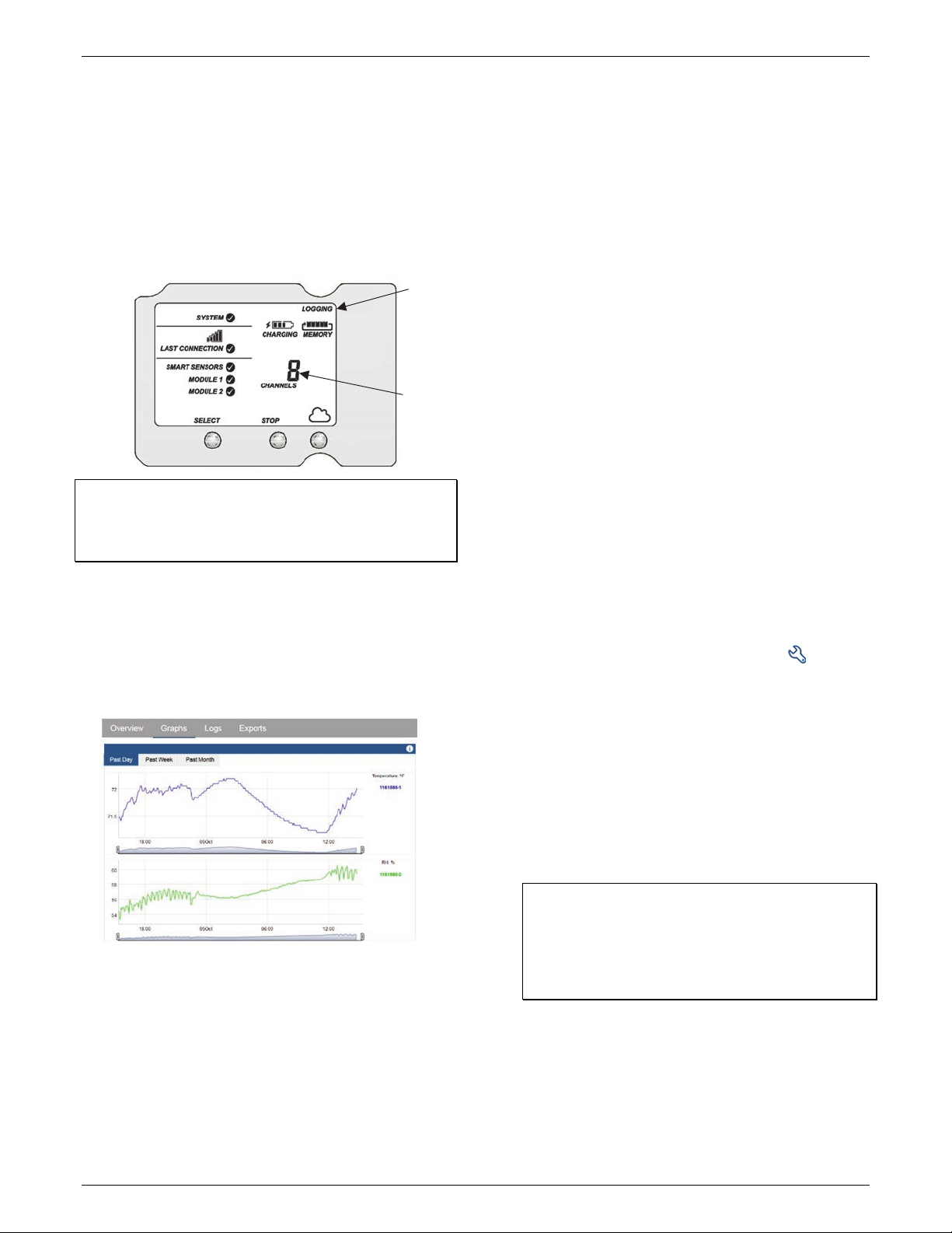
Once logging begins, “Logging” appears in the upper right
corner of the LCD as shown in the following example.
“Logging” will blink until the first logging sample is
recorded. At that point, it will stop blinking and remain
illuminated until logging is stopped. Also note that the
channels count on the LCD screen will be updated to
include any analog sensors that were enabled in HOBOlink.
Important: See Deploying and Mounting the Station for
installation steps and other deployment guidelines. If using the
station outdoors or in harsh indoor conditions, you must install
the sensor cable channels and the plates for weatherproofing.
Viewing Data in HOBOlink
Data is uploaded to HOBOlink each time the device connects.
For a snapshot of the latest conditions, click Devices and List
and click the device name to view the readings from the last
connection for smart sensors and logged analog sensors. You
can also view any enabled graphs as shown in the following
example.
Logged data is saved in a database. You can export this data on
demand as needed or set up automatic exports that are
delivered to email and/or FTP addresses on a schedule you
specify.
To download and export data:
1. In HOBOlink, click Data and Exports.
2. Click Create New Export.
3. Follow the instructions on the screen to select the name,
format, time zone, and time frame, and then the devices
and sensors to include in the export. Reorder the sensors as
needed.
4. Click Save to keep these settings for future use or click
Export Data to export immediately.
To set up a scheduled data delivery:
1. Click Data and then click Data Delivery).
2. Click Create New Delivery.
3. Under General Settings, type the name of the delivery
schedule and the frequency of delivery. Enable the Active
checkbox. Select other settings if desired.
4. Under Select Data to Export, choose the name of the
custom data export you want to be delivered (or follow the
previous set of steps to set up a custom data export).
5. Under Data Destination, select FTP/SFTP or Email for the
delivery method and fill in the appropriate fields.
6. Click Save. Data will then be delivered on the schedule you
selected.
For more information on Data Delivery, see the HOBOlink Help.
See also HOBOlink Help for other ways to monitor your station,
including setting up a map or using dashboards.
Setting System and Sensor Alarms
You can set up both system and sensor alarms in HOBOlink.
System alarms can trip when there is a missed connection, the
battery is low, or if there is a smart sensor failure. With a
sensor alarm, you can configure an alarm to trip at one level
and clear at another.
System Alarms
To add a system alarm:
1. In HOBOlink, click Devices and then List, and find the station
you want to configure. Click the arrow next to and select
Alarm Configuration.
2. Click Edit System Alarms.
3. For Missed Connection alarms:
a. Under Communication, select the Missed Connection
checkbox.
b. Set the length of time for HOBOlink to wait after the
station has missed a connection before an alarm trips.
c. Select the action to be taken when this alarm trips: send
an email or text. Enter the details and then select “Send
on Clear Also” if you want an email or text when the
alarm clears as well.
Important: Standard data fees and text messaging rates
may apply when using text notifications. Onset does not
charge a fee or guarantee delivery of text alerts, which is
subject to your carrier’s service and location. See the
HOBOlink Help for additional details on alarm
notifications.
d. Click Add Action if you want multiple actions to be taken
when the alarm trips (for example send an email and a
text).
4. For Battery Low and Sensor Failure alarms:
a. Under Device, select the Battery Low and/or Sensor
Failure checkboxes.
b. Select how you want to be notified when these alarms
trip: by email or text. Enter the appropriate addresses
“Logging”
appears
when
logging
begins
Channel
count
updated for
any enabled
analog
sensors
www.GlobalTestSupply.com
Find Quality Products Online at: sales@GlobalTestSupply.com
HOBO RX3000 Remote Monitoring Station Manual
15
and then select “Send on Clear Also” if you want an
email or text when these alarms clear as well.
5. Click Add Action if you want multiple actions to be taken
when the alarm trips (for example send an email and a
text).
6. Click Save. Changes will take effect the next time the station
connects to HOBOlink.
Red alarm symbols will appear in HOBOlink when these alarms
trip (if enabled).
Note for wireless sensors: If a wireless sensor mote goes
offline from the network for 30 minutes, the station will
automatically connect to HOBOlink to report the missing mote
regardless of any alarm settings in place. Unless the mote has
no battery power, it will continue logging data even if it is
offline from the network. Once the mote is back online, any
logged data will be uploaded during regular connections to
HOBOlink. Note: Once a mote is back online, it enters recovery
mode as HOBOlink receives the data logged while it was offline.
During this period of recovery, data for that mote will
temporarily be unavailable for data delivery, dashboards, and
data feeds. See the HOBOlink help for additional details.
Sensor Alarms
To add a sensor alarm:
1. In HOBOlink, click Devices and then List, and find the station
you want to configure. Click the arrow next to and select
Alarm Configuration.
2. Click Add a Sensor Alarm.
3. Select the sensor.
4. Select whether the alarm should trip above or below a
value or within a range.
5. Enter the sensor reading(s) for the alarm threshold.
6. Enter the number of logged data points you want the
station to record before the alarm trips.
7. If you selected the alarm to trip above or below a specific
reading, then select when the alarm should clear: above or
below the same value or a different value. Enter the value if
necessary.
8. Select the action to be taken when the alarm trips: send an
email or text or close, open, or pulse one of the three relays
if a relay module is installed. For email or text, enter the
details and then select “Send on Clear Also” if you want an
email or text when the alarm clears as well.
Important: Standard data fees and text messaging rates
may apply when using text notifications. Onset does not
charge a fee or guarantee delivery of text alerts, which is
subject to your carrier’s service and location. See the
HOBOlink Help for additional details on alarm
notifications.
9. Click Add Action if you want multiple actions to be taken
when the alarm trips (for example, close the relay and send
an email).
10. Add any optional notes for this alarm.
11. Click Save. Changes will take effect the next time the station
connects to HOBOlink.
12. Repeat steps 2 through 11 for each additional sensor alarm
you want to add.
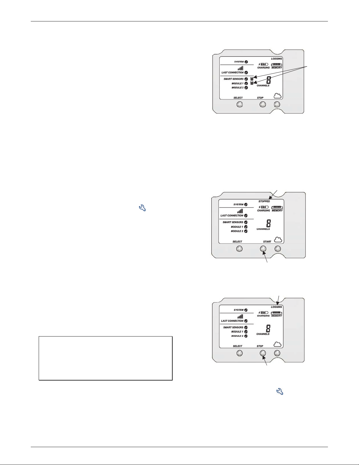
A red alarm symbol appears next to that sensor in HOBOlink
when it trips. An alarm symbol will also appear on the LCD.
Starting and Stopping Logging
You can start and stop logging with the Start/Stop button on
the station or from HOBOlink.
To start and stop logging with the station:
1. When the station is stopped, press the Start button to start
logging. The device will connect to HOBOlink (“Connection”
will blink on the LCD) and then logging will begin at the
logging interval specified for smart sensors, wireless sensors
and analog sensors (if applicable).
2. To stop logging, press the Stop button. Logging stops
immediately. Note that the station will continue to connect
to HOBOlink even if it is not logging.
To start and stop the station from HOBOlink:
1. Click Devices and then List, and find the station you want to
start or stop. Click the arrow next to and select
Start/Stop.
2. Click Start or Stop. The station will start or stop logging the
next time it connects to HOBOlink.
Tripped smart
sensor alarm
and analog
sensor alarm
Press this button to stop logging
Press this button to start logging
The station is logging
The station is stopped
www.GlobalTestSupply.com
Find Quality Products Online at: sales@GlobalTestSupply.com
HOBO RX3000 Remote Monitoring Station Manual
16
Adding or Removing Smart Sensors
To add or remove smart sensors from the station:
1. If the station is currently logging, press the Stop button to
stop it.
2. Press the Connect button and wait for the station to
connect to HOBOlink so that all the latest data is offloaded
before changing smart sensors.
3. If using the rubber cable channel, unscrew the plates and
push the cable channel out of the case. Open it to access
any smart sensors.
4. Unplug any smart sensors you wish to remove. Plug in any
new smart sensors.
5. Press the Select button to view the smart sensors on the
LCD screen.
6. Press the Search button for the station to detect all the
smart sensors currently connected.
7. Press the Start button to begin logging again. The station
will automatically connect to HOBOlink.
8. If using the rubber cable channel, grease and place any
smart sensor cables or plugs, reinsert the rubber cable
channel, and reinstall the plates. See Installing the
Weatherproof Rubber Cable Channel and Covers for details.
9. Make any configuration changes in HOBOlink as desired,
such as adding sensor labels or scaling (see Setting up the
Station).
Note that any existing alarms associated with removed sensors
will still be listed in HOBOlink. See the HOBOlink Help for details
on deleting alarms. Also, if you are using alarms to activate
relays, check that the relays are in the proper state.
Adding or Removing Modules
The RX3000 has two slots in which optional analog, relay, or
RXW Manager modules can be installed. You can add or
remove these modules as desired.
To add a module:
1. Stop the station if it is currently logging.
2. Press the Connect button and wait for the station to
connect to HOBOlink so that all the latest data is offloaded
before adding a new module.
3. Power down the station (unplug any charging device and
then disconnect the battery).
4. Insert the module into the left or right module slot.
5. Using a Phillips-head screwdriver, tighten the screw at the
bottom of the module.
6. If installing an RXW Manager module, plug the cable from
the RXW Manager mote into the jack on the module,
making sure the cable is inserted through the bottom of the
station case. Do not reconnect the power on the station
until the mote is plugged in as shown.
7. Plug in the battery and charging device, and wait for the
device to power up. Verify that the new module is listed on
the LCD screen with a checkmark.
8. The station should automatically connect to HOBOlink
(press the Connect button on the station if needed). Check
your station’s page to make sure the new module is listed.
9. Connect any analog sensors or relays (see step 7 in Setting
up the Station for details). Add any wireless motes (see
Adding or Removing Motes). Make any configuration
changes as needed in HOBOlink and start logging again
when ready.
WARNING: If you inadvertently install modules while the power
is on or, you must disconnect and then reconnect the battery
and charging device to guarantee proper operation. In addition,
if you did not plug the manager mote into the module while the
power was off, it may not be recognized by the station.
Disconnect and reconnect the battery and charging device.
To remove a module:
1. Stop the station if it is currently logging.
2. Press the Connect button and wait for the station to
connect to HOBOlink so that all the latest data is offloaded
before adding a new module.
3. Power down the station (disconnect the battery and unplug
any charging device).
4. Disconnect any analog sensors or relay devices. If removing
an RXW Manager module, unplug the RXW Manager mote.
5. Using a Phillips-head screwdriver, unscrew the bottom
screw on the module until loosened (it will remain attached
to the module).
6. With your fingers on the top and bottom edges of the
module, carefully pull it out of the slot.
7. Plug in the battery and charging device. Make sure the
station connects to HOBOlink (press the Connect button on
the station if needed).
8. Make any configuration changes as needed in HOBOlink and
start logging again when ready.
WARNING: If you inadvertently remove modules while the
power is on, you must disconnect and then reconnect the
battery and charging device to guarantee proper operation.
Note that any existing alarms associated with removed
modules will be listed in HOBOlink. See the HOBOlink Help for
details on deleting alarms. Also, if you are using alarms to
activate relays, check that the relays are in the proper state.
www.GlobalTestSupply.com
Find Quality Products Online at: sales@GlobalTestSupply.com

HOBO RX3000 Remote Monitoring Station Manual
17
Adding or Removing Motes
To add a mote to the RX Wireless Sensor Network:
Important: Keep the mote near the RX3000 station
while completing these steps.
1. If the LCD is blank on the RX3000 station, press any button
to wake it up.
2. Press the Select button once (which shows the number of
smart sensors installed) and then press it again once if the
HOBO RXW Manager is installed in the left slot (module 1)
or twice if it is installed on the right slot (module 2).
3. Press the Search button (the magnifying glass). The
magnifying glass icon will blink while the RX3000 is in search
mode.
4. Open the mote door and install the batteries if you have not
already done so.
5. Press the button on the mote for 3 seconds. The signal
strength icon will flash and then cycle.
6. Watch the LCD on the mote.
The green LED blinks quickly while the mote searches for a
network to join and then blinks slowly while it completes
the network registration. Once the mote has finished
joining the network, the green LED turns off and the blue
LED then blinks indefinitely while the mote is part of the
network.
Note: If the mote cannot find the network or has trouble
remaining connected during this process, make sure the
mote is in a vertical, upright position and within range of
the station.
7. Repeat steps 4–6 for any additional motes to add.
8. Press the Search button (the magnifying glass) on the
RX3000 station to stop searching for motes.
Measurements will be recorded at the logging interval specified
in HOBOlink, transmitted to the RX3000 station, and uploaded
to HOBOlink at the next connection interval (readout).
To remove a mote from the RX Wireless Sensor Network:
a. In HOBOlink, click Devices and then List, and find the
station with the mote you want to delete. Click the
arrow next to and select Module/Sensor
Configuration.
Press this button to view the module
where the RXW Manager is installed
Press this button for 3
seconds for the mote to
join the network
This network connection
“x” icon blinks while the
mote completes the
registration process,
which may take up to
five minutes.
Once the mote has finished joining
the network, the “x” icon is
removed and the channel count on
the station LCD increases by the
number of measurement channels
for the mote plus the battery.
Press this button so the station is ready
to have motes join the network
This signal strength icon
blinks while searching for
a network.
Once a network is found,
the icon will stop flashing
and the bars will cycle from
left to right.
c. d.
a. b.
Press this button again to
stop searching for motes
www.GlobalTestSupply.com
Find Quality Products Online at: sales@GlobalTestSupply.com

HOBO RX3000 Remote Monitoring Station Manual
18
b. Select the mote serial number or name from the
Configuration menu as shown in the following example.
c. Click Delete to remove the mote from the network.
d. If the mote you are deleting is currently active on the
network (i.e. powered up and transmitting data), the
station will need to connect to HOBOlink to complete
the removal process. Otherwise, the mote will not
officially leave the network and can attempt to
automatically rejoin the network in the future. To
connect to HOBOlink, press the Connect button on the
station. Once the station is connected, a command is
sent to the station and the mote permanently leaves the
network.
Managing Connections to HOBOlink
The station will connect to HOBOlink on the connection interval
you selected in Readout Configuration.
To change the connection schedule:
1. Click Devices and then List, and find the station you want to
configure. Click the arrow next to on the Devices page
and select Readout Configuration.
2. Set the connection interval. For the RX3003 and RX3004
cellular models, the minimum connection interval depends
on your communication plan.
3. If you wish to set up a second connection interval, select
the “Night Mode” checkbox. Select when night mode
should begin and end and then enter the connection
interval you want to use during that part of the day.
4. Click Save. The changes to the connection interval will take
place the next time the station connects to HOBOlink.
You can also connect to HOBOlink from the station at any time,
regardless of the connection schedule. Press the Connect
button on the station to connect to HOBOlink. Unless the
station is running on a night mode connection interval, the
normal connection schedule will then restart after the
connection is complete. For example, a station is configured to
connect hourly and the last connection on its regular schedule
occurred at 10:05. If you use the Connect button on the station
to connect to HOBOlink at 10:15, the next connection will then
be about 11:15 based on the one-hour connection interval.
Similarly, if a station misses a connection, the connection
schedule will shift depending on the time of the next successful
connection. While the station is using a second, night mode
schedule, all connections will follow that schedule only; any
extra connections while the station is in night mode will not
cause a shift in the connection schedule.
Also note that the station will connect to HOBOlink when the
device is powered up and when you press the Start button.
For RX3003 and RX3004 cellular models: All connections to
HOBOlink count toward your communications plan. If the
station is nearing its limit for monthly cell use, minimize
unscheduled connections. This includes any connections for
alarms or changes you make to the connection schedule. You
can also increase the connection interval to reduce the number
of connections to HOBOlink per day. Check the Device
Information section on your station page in HOBOlink to check
the status of the monthly communications plan usage for the
station.
Checking Latest Conditions with HOBOware
The RX3000 Manager within HOBOware and HOBOware Pro is
available for showing the current sensor readings in an RX3000
Station connected to a computer. To do this:
1. Connect the station to the computer with a USB cable and
open HOBOware.
2. From the Device menu in HOBOware, select Manage
RX3000. Note for Windows: You may see a warning that
Windows Firewall has blocked some features. Select
Domain networks and click Allow Access.
3. In the RX3000 Manager, the Latest Conditions panel shows
the currently configured sensors and modules for the
device. Click the refresh button in the Latest Conditions
panel to take a measurement for each sensor and display
the value. (Note: Sensor readings do not refresh
automatically.) You can also view general information about
the RX3000 Station in the Device information panel.
4. Close the RX3000 Manager when done and disconnect the
USB cable.
Note: The Latest Conditions and Device Information available in
the RX3000 Manager are for reference only. Use HOBOlink to
view complete station details, access logged data, and
configure the device.
Deploying and Mounting the Station
Follow the guidelines and steps in this section for deploying and
mounting the station.
Deployment Guidelines
When deploying the station:
• Check the signal strength on the LCD in the location you
wish to deploy the station to make sure it will be able to
reliably connect to HOBOlink (RX3002 Wi-Fi and RX3003
and RX3004 cellular models). The station may have
difficulty connecting if there is only one bar illuminated in
the Wi-Fi or cellular LCD symbol. (The signal strength
shown on the LCD is from the last connection.)
• The RX3003 and RX3004 cellular models must be mounted
at least one foot from all sensors to avoid interference
from the built-in radio module and antenna with the
measurements made by the sensors.
www.GlobalTestSupply.com
Find Quality Products Online at: sales@GlobalTestSupply.com

HOBO RX3000 Remote Monitoring Station Manual
19
• Make sure the station remains in a vertical position once it
is placed in its deployment location. If it is mounted
horizontally, the battery could be damaged over time as it
is charged and the antenna (if applicable) will not have
optimal range.
• If you haven’t already done so, plug in an AC adapter, solar
panel, or other external power source to keep the battery
charged.
• If you are using a wind speed/direction sensor or if the
station will be installed on a roof or in a location with
exposure to lightning, use the grounding wire included
with this station and ground the tripod or mast using
appropriate grounding, such as the Grounding Kit (M-
GKA). A grounding wire may also reduce potential sensor
errors that can result from installing near other radio or
electrical equipment or antennas. See Installing the
Grounding Wire.
• Make sure all cables and wires are fastened securely,
routed through the cable access openings, and placed in
the rubber cable channels. Any empty holes in the cable
channels need to be filled with the appropriate size plug to
ensure the station is weatherproof. See Installing the
Weatherproof Rubber Cable Channel and Covers.
• Do not store excess sensor cable wire coiled inside the
station case or within one foot outside the case.
• Protect cables and wires with conduit. Exposed cables can
be chewed by rodents.
• Make sure the total cable length for all installed smart
sensors does not exceed 100 m (328 ft).
• Consider using a padlock to restrict access to the station.
With the station door closed, hook a padlock through one
of the latches on the right side of the door and lock it.
When setting up the RX Wireless Sensor Network:
• Stay close to the RX3000 station when adding motes to the
wireless network because you will need to access both the
station and the mote at the same time. After the mote has
successfully joined the wireless network, you can then
move it to its deployment location.
• Check the signal strength on the mote LCD on the location
where you want to place the mote. If there is only one or
two bars on the signal strength indicator, consider moving
the mote to a location where the signal strength is
stronger.
• Make sure motes are mounted a minimum of 1.8 m (6
feet) above the ground or vegetation to help maximize
distance and signal strength as shown below.
• Consider using a plastic pole such as PVC to mount the
motes.
• Make sure each sensor mote and repeater is positioned so
that the built-in solar panel receives optimal sunlight
throughout each season as shown. It may be necessary to
periodically adjust the mote position as the path of the
sunlight changes throughout the year or if tree and leaf
growth alters the amount of sunlight reaching the solar
panel.
• Obstructions between motes can prevent reliable network
communication. If the mote is blocked by a small
obstruction (e.g. a pole, the RX3000 station, shrubbery),
then move the mote to a location where the obstruction is
not blocking the path to the nearest mote. If there is a
change in elevation between motes or a large obstruction
is in the way (e.g. a building or tree), then either reposition
the mote until there is full line of sight to the next mote or
add a repeater between them.
• There should not be more than five motes in any direction
at their maximum transmission range from the RXW
Manager. Data logged by a wireless sensor must travel or
“hop” across the wireless network from one mote to the
next until it ultimately reaches the RXW Manager at the
RX3000 station. To make sure the data can successfully
travel across the network, the mote should not be more
than five hops away from the manager.
• Use the Map feature in HOBOlink for a bird’s eye view of
the network and wireless paths. See the HOBOlink Help for
details on this and other ways to monitor the status of
your network and sensor data.
• Use cable ties or screws to mount the mote via the holes
on the mounting tabs.
• Make sure the mote remains in a vertical position once it is
placed in its deployment location for optimal network
communications.
www.GlobalTestSupply.com
Find Quality Products Online at: sales@GlobalTestSupply.com

HOBO RX3000 Remote Monitoring Station Manual
20
• Make sure the mote door is closed, with both latches fully
locked to ensure a watertight seal.
• Consider using a 3/16 inch padlock to restrict access to the
mote. With the mote door closed, hook a padlock through
the eyelet on the right side of the door and lock it.
• Mount the manager as high as possible above the RX3000
station to increase the radio signal and line of sight.
Installing the Grounding Wire
Insert the grounding wire through the larger of the two cable
access openings and plug it into the ground connector. You may
need pliers to connect it to the station. The grounding wire
must be connected to a properly grounded mast (typically on
one side of the U-bolt) when the station is mounted.
Mounting the Station
Attach the mounting plates with a Phillips-head screwdriver to
the back of the station to mount it on a flat surface. Mount the
station vertically to a wall or board using screws.
You can also mount the station vertically to a mast or pole and
tripod using U-bolts (unscrew the nut on the U-bolt to place
around the mast or pole). Screw the mounting plates to the
back of the station as shown above. Make sure the mounting
plates are mounted against the flat part of the U-bolt saddle
clamps. If using the grounding wire, attach it to one end of the
U-bolt. Refer to the Tripod Setup Guide for full details.
Installing the Weatherproof Rubber Cable
Channel and Covers
Important: This is required for outdoor and weatherproof
deployments and recommended for harsh indoor environments
where debris could enter the station.
1. Make sure all sensors and cables are installed, including the
solar panel, AC adapter cable, or external DC power cable,
and the grounding wire.
2. Grease one of the two rubber cable channels.
a. Apply a small amount of silicone grease (about the size
of a pea) onto your fingertip.
b. Lightly coat all four outer edges on the rubber cable
channel with grease.
c. Open the cable channel and lightly coat the inside of
both halves (the part with the grooves).
3. Lightly coat each cable with grease.
4. Place the greased cables in the channel grooves.
a. Open the greased rubber cable channel so that the
channel’s hinged side is oriented to the left.
b. Place each cable or wire into a single groove in the cable
channel, installing them from left to right.
• For the large cable channel, place smart sensor cables
in the grooves. If using the grounding wire, place the
black portion of it into the rightmost hole in the cable
channel (the hole farthest from the hinged side).
• For the small cable channel, place the AC adapter or
solar panel cable and any analog sensor cables or relay
wires in each of the grooves. Place larger cables in the
five grooves on the left closest to the hinged side and
smaller cables in the five grooves on the right.
Connect the grounding wire here
Cables placed
in grooves of
rubber cable
channel
Screw the
mounting
plates to
the back of
station
Use the holes on the mounting plates to
affix the station to a board or flat surface
Attach the
station to a
pole or mast
with U-bolts
www.GlobalTestSupply.com
Find Quality Products Online at: sales@GlobalTestSupply.com
Other manuals for RX3000 Series
9
This manual suits for next models
4
Table of contents
Other Hobo Measuring Instrument manuals

Hobo
Hobo RX3000 Series User manual

Hobo
Hobo RXW-SMC-900 User manual

Hobo
Hobo MicroRX RX210 Series Instruction Manual

Hobo
Hobo MX series User manual

Hobo
Hobo RX3000 Series User manual

Hobo
Hobo RX3000 Series User manual

Hobo
Hobo MicroRX Station Series User manual

Hobo
Hobo RX3000 Series User manual

Hobo
Hobo RX3000 Series User manual

Hobo
Hobo MicroRX Station RX2102 User manual


