2-3-0-246/ISS10/NOV09
HOCHIKI ESP SENSOR & BASE RANGE
INSTALLATION INSTRUCTIONS
Products Covered: ALG-E, ALG-E(NP), ALG-EN, ALG-ENM / AIE-E,
AIE-E(NP) / ACA-E / ACB-E, ACB-EM, ACB-EW / YBN-R/3, YBN-R/3M
Introduction
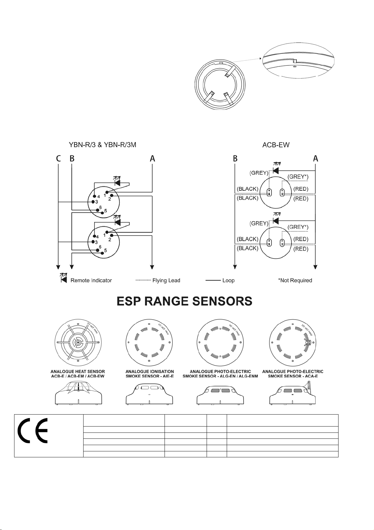
The analogue Sensors listed above can all use a Common Mounting Base (YBN-R/3 or YBN-R/3M in the case of marine
approved sensors), which is electronics free, the Base Sounder (YBO-BS), the Base Sounder Beacon (YBO-BSB) and
the Short Circuit Isolator Bases (YBO-R/SCI or YBO-R/SCIM in the case of marine approved sensors) except the ACB-
EW, which utilises flying leads. Please note that a sensor suffixed by NP is a non-pulsing type and the LED’s will not
flash when polled, but the LED’s will illuminate when the sensor is in a fire condition. The ACA-E, ACB-E, ACB-EM,
ALG-EN, ALG-ENM and ACB-EW polling LED can be turned off at the Control Panel (Control Panel compatibility needs
to be checked to verify if this facility is supported). Follow the guidelines below before installation and maintenance.
Hochiki cannot guarantee a sensor’s performance if these guidelines are not followed.
Caution
Hochiki ESP range sensors cannot be used to prevent fire itself, they are only intended to detect a certain characteristic
of fire. The ACA-E (Heat mode only), ACB-E, ACB-EM and ACB-EW sensors are used to detect conditions and changes
in temperature and cannot detect smoke and other phenomena. When installing the sensor, check that the location of
each one has been planned according to appropriate fire regulations or recommendations. Please note that the ACA-E
Multi-Sensor default mode is optical/heat, if this sensor is to be programmed to change modes i.e.: - optical to heat then
the ACA-E should be spaced as a standard Heat Sensor.
The sensor and base combination should be installed to the following guidelines:
Ensure the Sensor and Base are installed in accordance with Local Standards or Regulations.
Sensor and Base combinations should only be installed where ambient temperatures are between -10°C to +50°C
and where the condensation and moisture levels are between 10% to 95% RH – Non-condensing (at 40°C).
Only install in suitable environments, the following should be avoided.
Situations in which condensation exists.
Situations in which corrosive gases exist.
Situations in which dust or steam exists.
Situations in which obstacles exist, which could impede airflow to the sensor.
Hazardous areas.
Do not use a high voltage tester on any Sensor or any Base with electronics (YBO-BS, YBO-BSB, YBO-R/SCI &
YBO-R/SCIM).
Certain actions can cause permanent damage to the sensor. If the sensor is subjected to any of the following it should
not be used:
Disassembly and re-assembly.
Impact or shock.
Touching the thermistor (ACB-E, ACB-EM, ACB-EW) Heat sensors and ACA-E Multi-Sensor only).
If damage is suspected after a fire has occurred, the sensor should be replaced. After installation, all sensors on the fire
alarm system should be tested to confirm correct operation. Installation and maintenance should only be carried out by
suitably trained engineers. Sensor operation should not be tested with a naked flame or open fire. Operation should
only be checked by equipment that is capable of exceeding the required detection threshold.
The sensor must be subject to periodic maintenance during regular service visits. This period should be outlined in the
appropriate standards or recommendations. If there are no such standards existing, Hochiki recommend that the
minimum period of maintenance should be 1 year and that the following should be taken into account:
A regular operation test should be performed.
A visual check for staining and mechanical damage should be made.
A dust cover is included with the sensor to prevent contamination during installation. The dust cover must be removed
for the sensor to operate.
Setting the Address
Each sensor must have its address set before system operation. Using the installation plan that shows the proper
location for each sensor, find the address for the sensor to be installed. Check that the address and location on the plan
match correctly. Address is any number from 1 to 127. For address setting, use the address programmer and write the