manuals.online logo
Brands
  1. Home
  2. •
  3. Brands
  4. •
  5. Intelbras
  6. •
  7. Accessories
  8. •
  9. Intelbras IVA 5015 digital User manual

Intelbras IVA 5015 digital User manual

User’s Manual
IVA 5015 digital
IVA 5015 digital
Single beam active sensor
Congratulations, you just have purchased a product with Intelbras quality and
safety.
IVA 5015 Digital sensor was developed with a digital circuit for signal processing
that can identify the pair of transmitter-receiver more effectively in order to avoid
external interferences. It can be installed at indoor, half-open or outdoor environ-
ments without performance loss, preventing false shots in several applications.
This sensor is able to quickly identify beam obstruction and activate the circuit
responsible for operation, in an alarm circuit or pinch protection. Read the product
introductory information carefully for the correct use of sensors.
Caution and safety
» LGPD - General Law for the Protection of Personal Data: Intelbras does not access, trans-
fer, capture, or perform any other type of treatment of personal data from this product.
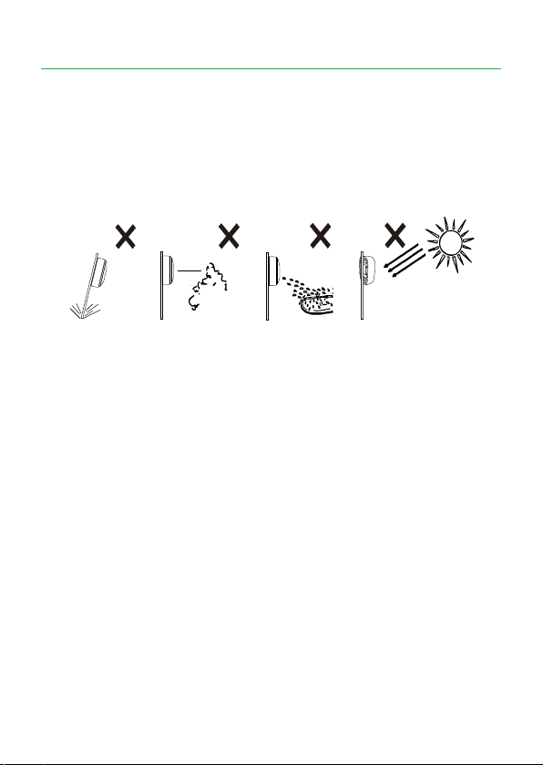
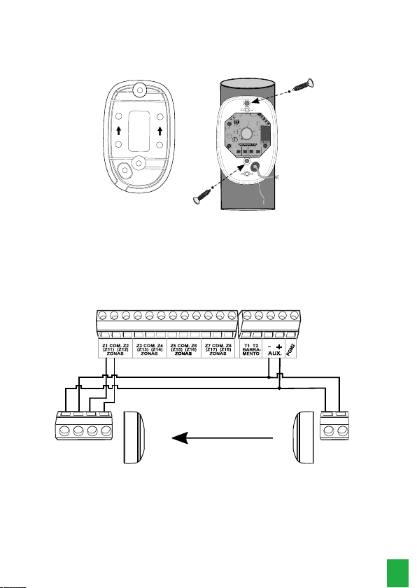
» Install the sensor in a stable and shake-free place.
» Install the Transmitter and Receiver to be aligned.
» Do not install the receiver with the lenses directed toward the sun.
» Do not install the sensor in a place where the beams can be obstructed. Check if
there is no plants, branches or other objects that may obstruct the sensor beams.
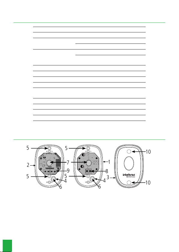
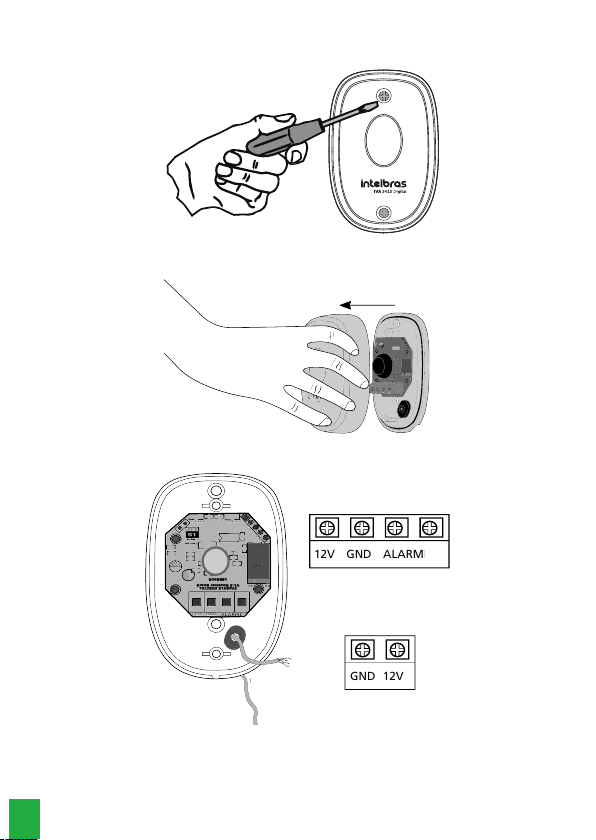
» Make sure the cable passage side is faced down, in order to prevent water from
entering into it.
» Make sure the sealing rubber is installed in order to avoid water and insects en-
tering into it.
» Use a damp cloth to clean the exterior of the sensor, and never use chemical
products.
» Correctly size-up the source and power supply cable.
» Do not leave the cable exposed to the sun, rain or humidity.
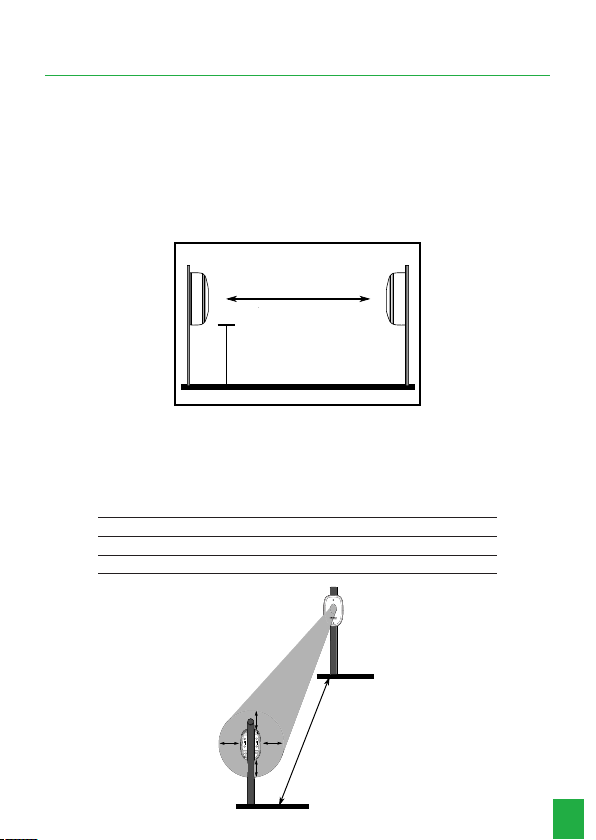
» Do not install the sensor farther than the recommended distance.
» Install the sensor at a distance more or equal to 50 cm from oor surface.
» Check of the sensor power supply is between 12 and 24 Vdc, if the gate con-
trolling board does not supply voltage enough to power the sensor or it is unsta-
ble, it is recommended to use a power supply exclusively for the product.
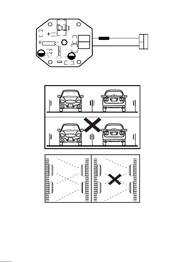
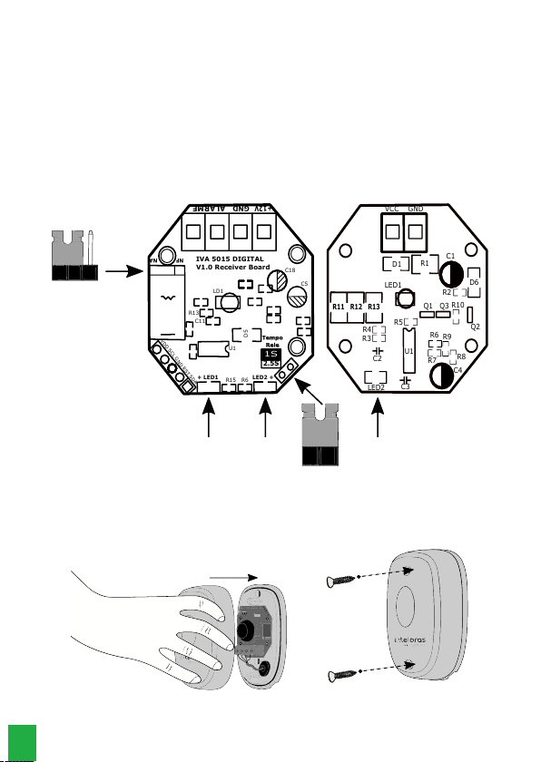
» Avoid installing the receiver near to sources of electromagnetic noises. After ins-
talling, perform tests to check if the product is working correctly. If there is inter-
ference, change the Transmitter position with the Receiver.
» If the sensor is installed on a smooth ans polished oor, it cannot shot due to the
infrared beam reection on the oor or walls.To prevent such situation, connect in
series of 1k to 10 k resistor with the transmitter (TX) positive wire (Vdc).
Note: upon connection the resistor, make sure that there is reection, cutting the
beam in several positions between TX and RX. The more the distance, the more
the resistor value.
R11 R12 R13
R4
R3
C2
LED2
U1
C3
LED1
D1 R1
VCC GND
R2
D6
Q1 Q3 R10
Q2
R5
R6
R8
R9
R7
C4
C1
Placa Transmissor
GND
VDC
Fonte
1K a 10K
Transmitter board
1K a 10K
Power Supply
» If you need to install more pairs in similar conditions as shown below, install the
transmitter (TX) and receiver (RX) making sure a pair does not affect one another.
RX RXTX TX
TX RX
RX TX
Correto
Incorreto
Correct
Incorrect
RX
TX
Correto Incorreto
RX TX
TX
TX
RX
RX
Correct Incorrect
Note: it is not recommended to cross install two pairs of sensors, as shown in the
image above, in application where an obstacle may cause reection to the infrared
beam, as a car, for example.
Summary
1.Technical specications 6
2.Product 6
3.Installation 7
Term of Warranty 11
6
1. Technical specications
Power supply voltage 12 ~ 24 Vdc
Consumption current ≤50 mA @ 12 Vdc
Reach Internal 30 m
External 15 m
Alarm outlet
Congurable NO/NC output
1 A @ 24 Vdc
1 A @ 127 Vac
Relay opening time 1s or 2,5s ± 10%
Response time 50 ms
Alignment indication LED alignment (green)
Shot indication Shot LED (red)
Solar lter for outdoor
environments Yes
Operating temperature -10 ºC to + 55 ºC
IP Protection level IP55
Colors Black
Size (W × H × D) 48,5 × 25 × 76,5 mm
2. Product
5
5
5
2
3
4
1
6
4
6
7
98
10
Tempo
Rele
NA
NF
+12V
GND
ALARME
1S
2.5S
+ LED1 LED2 +
R15 R6
VDD SCL GND RST SDA
U1
C18
C5
5D
C11
R13
LD1
IVA5015DIGITAL
V1.0ReceiverBoard
1886406
R11 R12 R13
R4
R3
C2
LED2
U1
C3
LED1
D1 R1
VCC GND
R2
D6
Q1 Q3 R10
Q2
R5
R6
R8
R9
R7
C4
C1
5
10
1. Transmitter
2. Receiver
3. Front cover
4. Sealing rubber
5. Orice for xing screws
6. Cable passage
7. Lenses
8. Terminal block TX
9. Terminal block RX
10. Orice for xing screws
7
3. Installation
1. Before starting to install, it is necessary to dene the distance for the IVA 5015
Digital sensor. We recommend to install this sensor in a place higher or equal to
50 cm from the oor and the maximum distance between TX and RX must be 15
m for outdoor environments and 30 m for indoor environments;
Note: in outdoor environments with high mist or rain rate, install the sensor at
max 50% from the specied distance for outdoor environments.
For correct installation, follow the procedure.
TX
RX
≥
Ambiente interno 30m
Ambiente externo 15m
50cm
≥ 50 cm
Indoor environment 30 m
Outdoor environment 15 m
2. If there area more than one IVA 5015 Digital infrared transmission (TX) source
at the installation location, follow the vertical protection distance (VPD) and the
horizontal protection distance (HPD), according the following table, in order to
prevent interference to the receiver (RX);
Distance between RX and TX
5 m 10 m 15 m
Horizontal protection distance (HPD) 0,8 m 1,6 m 2,4 m
Vertical protection distance (VPD) 1,1 m 1,6 m 2,2 m
Distância entre RX e TX
DPH
DPV
RX
TX
Distance between RX and TX
8
3. Open the sensor removing the bolts in the front part;
4. Remove the front cover pulling forward;
1S
2.5S
Tempo
Rele
+12V
GND
ALARME
5. Pass the cable through the orice and connect it to the terminal block;
Tempo
Rele
NA
NF
+12V
GND
ALARME
1S
2.5S
+ LED1 LED2 +
R15 R6
VDD SCL GND RST SDA
U1
C18
C5
5D
C11
R13
LD1
IVA5015DIGITAL
V1.0ReceiverBoard
1886406
Cabo
12V GND ALARME
GND 12V
RECEPTOR
TRANSMISSOR
Cable
TRANSMITTER
RECEIVER
9
6. Attach the receiver and transmitter using two screw passage points located in the
product base, at a height equal or higher than 50 cm from the oor with the cable
passage faced down, the indication arrows at the base must be faced up;
Tempo
Rele
NA
NF
+12V
GND
ALARME
1S
2.5S
+ LED1 LED2 +
R15 R6
VDD SCL GND RST SDA
U1
C18
C5
D5
C11
R13
LD1
IVA5015DIGITAL
V1.0ReceiverBoard
7. Turn on the power supply according to the polarity indicated in the receiver and
transmitter board (12 ~ 24 Vdc), this sensor has a reverse polarity protection;
8. Connect the alarm wires in the gate controlling board or in the alarm center zone
input;
Note:
check in the gate manual or alarm center, which is the connection mode is used.
An example of connection to Intelbras alarm center is shown below.
VCC GND ALARME VCC GND
Receptor
Transmissor
Receiver Transmitter
10
9. After installing, check the correct operation cutting the beams, obstruct the beams
with hand or any kind of shield, and check if the receiver triggers, observing the
alarm signal through red LED and relay activation. The relay (alarm) outlet can
be adjusted according to NO or NC application and the relay opening time can
be set as 1s or 2.5 s. In case o use with alarm center, it is recommended to use
with a timing of 2.5 s.
» Relay output: NA (normally open) factory standard.
» Relay opening time: 1st factory pattern.
Tempo
Rele
NA
NF
+12V
GND
ALARME
1S
2.5S
+ LED1 LED2 +
R15 R6
VDD SCL GND RST SDA
U1
C18
C5
D5
C11
R13
LD1
R11 R12 R13
R4
R3
C2
LED2
U1
C3
LED1
D1 R1
VCC GND
R2
D6
Q1 Q3 R10
Q2
R5
R6
R8
R9
R7
C4
C1
Jumper Relé
NA / NF
Jumper Tempo
Relé
LED Vermelho LED Verde LED Verde
Placa Receptor Placa Transmissor
IVA 5015 DIGITAL
V1.0 Receiver Board
Receiver board
Red LED Green LED Green LED
Timer jumper
relay
Jumper Relay
NA / NF
Transmitter board
10. To close the sensor, attach the front cover and then, insert and tighten the screws
as shown in the image below:
1S
2.5S
Tempo
Rele
+12V
GND
ALARME
1S
2.5S
Tempo
Rele
+12V
GND
ALARME
11
Term of Warranty
It is expressed that this contractual warranty is granted according to the following
conditions:
Customer name:
Customer’s signature:
Tax Invoice No.
Date of Purchase:
Model: Serial No.:
Retailer
1. All parts, pieces and components of this product are warranted against any man-
ufacturing defects, which may arise within a period of 1 (one) year - being 90
(ninety) days of legal warranty and 9 (nine) months subject to contractual warran-
ty - from the date when the Customer purchased the product, according to the
product purchase tax invoice, which is an integral part of this Term throughout
the Brazilian territory. This contractual warranty expressly includes the product ex-
changes in case of manufacturing defect. If no manufacturing defect is conrmed,
but there is a failure due to improper use, the Customer shall bear any of these
incurred expenses.
2. The product must be installed according to the Product Manual and/or Installation
Guide. If your product requires to be installed and congured by a skilled techni-
cian, your should seek for a reliable and skilled professional, but the costs of such
services are not included in the product price.
3. Once the defect is conrmed, the Customer shall contact immediately the nearest
Authorized Service listed in the report provided by the manufacturer, they are the
only professionals authorized to check and remedy the defect within the warranty
term provided herein. It it is not observed, the warranty is void, characterized as
product infringement.
4. Eventually, if the Customer requests service at home, he/she may contact the near-
est Authorized Service to ask for fee quotation of a technical visit. If it is necessary
to withdraw the product to be repaired, the incurred expenses such as transpor-
12
tation and insurance costs, including taking and return after repaired, are under
responsibility of the customer.
5. The warranty will be entirely voided if any of the following cases occur: a) if the
defect is not due to manufacturing, but caused by the Customer or by third parties
foreign to the manufacturer; b) if the product damages are caused by accident,
disasters, agents of nature (lightning, ooding, landslide, etc.), humidity, network
voltage, over-voltage caused by accident or excessive network voltage uctua-
tions), installation/use in disagreement with the user’s manual or due to natural
wear of parts, pieces and components; c) if the product had suffered any effects of
chemical, electromagnetic, electric or animal (insects, etc.) nature; d) if the product
serial number was altered or erased; and e) if the appliance is awed.
6. This warranty does not cover data loss, therefore, in case of a product, it is advis-
able to the Customer to regularly make secure backup of the product data.
7. Intelbras is not liable for the installation of this product, as well as eventual at-
tempts of fraud and/or sabotage in their products. Keep software and applications
up to date, and if necessary, the required network protections against intrusions
(hackers). The equipment is warranted against defects under normal conditions of
use, and it is important to bear in mind that, because it is an electronic equipment,
it is not protected from attempts of frauds or misleading actions that may interfere
in its correct operation,
8. After its useful life, the product must be delivered to an Intelbras authorized sup-
port service or perform environmentally proper nal disposal in order to avoid
environmental or health impacts. If you prefer, useless cells and batteries as well
as other Intelbras branded electronic appliances may be disposed at any Green
Eletron collection points (electro-electronic residues management company to
which we are associated). If you have any questions about the reverse logistics
process, contact us by phone (48) 2106-0006 or 0800 704 2767 (from Monday to
Friday at 8 AM to 8 PM, and on Saturday at 8 AM to 6 PM) or via e-mail suporte@
intelbras.com.br.
Also under these supplementary Term of Warranty, Intelbras S/A reserves the right
to alter general, technical or aesthetics features without prior notice.
The manufacturing process of this product is not subject to ISO 14001 requirements.
All images in this manual are for illustrative purposes only.
01.21
Made in China
Customer Support: (48) 2106 0006
Forum: forum.intelbras.com.br
Support via chat: intelbras.com.br/suporte-tecnico
Support via e-mail: [email protected]
Customer Service: 0800 7042767
Where to buy? Who installs it? 0800 7245115
Imported to Brazil by: Intelbras S/A – Indústria de Telecomunicação Eletrônica Brasileira
Rodovia SC 281, km 4,5 – Sertão do Maruim – São José/SC – 88122-001
CNPJ 82.901.000/0014-41 – www.intelbras.com.br

Other Intelbras Accessories manuals

Intelbras IVP 7001 MW EX User manual

Intelbras

Intelbras IVP 7001 MW EX User manual

Intelbras IVP 3011 Cortina User manual

Intelbras

Intelbras IVP 3011 Cortina User manual

Intelbras IVP 2000 SF User manual

Intelbras

Intelbras IVP 2000 SF User manual

Intelbras IVP 4000 smart User manual

Intelbras

Intelbras IVP 4000 smart User manual

Intelbras IVP 5301 PET PRO User manual

Intelbras

Intelbras IVP 5301 PET PRO User manual

Intelbras IVP 1000 PET User manual

Intelbras

Intelbras IVP 1000 PET User manual

Intelbras IVP 4000 smart User manual

Intelbras

Intelbras IVP 4000 smart User manual

Intelbras IVP 1000 PET User manual

Intelbras

Intelbras IVP 1000 PET User manual

Intelbras XAS Light User manual

Intelbras

Intelbras XAS Light User manual

Intelbras IVA 3015X User manual

Intelbras

Intelbras IVA 3015X User manual

Intelbras XAS 4010 SMART User manual

Intelbras

Intelbras XAS 4010 SMART User manual

Intelbras XAS Smart User manual

Intelbras

Intelbras XAS Smart User manual

Intelbras IVA 7100 Dual User manual

Intelbras

Intelbras IVA 7100 Dual User manual

Intelbras IVP 2000 SF User manual

Intelbras

Intelbras IVP 2000 SF User manual

Intelbras IVP 7000 MW EX User manual

Intelbras

Intelbras IVP 7000 MW EX User manual

Intelbras XAS Smart User manual

Intelbras

Intelbras XAS Smart User manual

Intelbras IVP 3011 Teto User manual

Intelbras

Intelbras IVP 3011 Teto User manual

Intelbras IVP 3000 MW User manual

Intelbras

Intelbras IVP 3000 MW User manual

Intelbras IVA 3070 X User manual

Intelbras

Intelbras IVA 3070 X User manual

Intelbras IVP 3000 MW User manual

Intelbras

Intelbras IVP 3000 MW User manual

Intelbras IVP 3000 CF User manual

Intelbras

Intelbras IVP 3000 CF User manual

Intelbras IVP 8000 Pet User manual

Intelbras

Intelbras IVP 8000 Pet User manual

Intelbras iIVA 5040 AT User manual

Intelbras

Intelbras iIVA 5040 AT User manual

Intelbras IVP 7001 MW PET User manual

Intelbras

Intelbras IVP 7001 MW PET User manual

Popular Accessories manuals by other brands

Glastender BB48-L1-BSN(LR) Features & specifications

Glastender

Glastender BB48-L1-BSN(LR) Features & specifications

Chef's Choice 476 Instructions for use

Chef's Choice

Chef's Choice 476 Instructions for use

DELTA PLUS AN022 operating instructions

DELTA PLUS

DELTA PLUS AN022 operating instructions

SUNFLEX SF125 Assembly instructions

SUNFLEX

SUNFLEX SF125 Assembly instructions

Tripp Lite B114-002-R owner's manual

Tripp Lite

Tripp Lite B114-002-R owner's manual

woodmizer PD200 Series Safety, Operation, Maintenance & Parts Manual

woodmizer

woodmizer PD200 Series Safety, Operation, Maintenance & Parts Manual

Chef's Choice EdgeSelect 120 user manual

Chef's Choice

Chef's Choice EdgeSelect 120 user manual

New Air AB-1200B-REM owner's manual

New Air

New Air AB-1200B-REM owner's manual

Sewhacnm SI 520 user manual

Sewhacnm

Sewhacnm SI 520 user manual

Alfalaval Blue BD Series instruction manual

Alfalaval

Alfalaval Blue BD Series instruction manual

Baicells Nova-227 installation guide

Baicells

Baicells Nova-227 installation guide

smart things Outlet manual

smart things

smart things Outlet manual

POS-X iSAPPOS 9A+ quick guide

POS-X

POS-X iSAPPOS 9A+ quick guide

WHISPER KOOL WK 2500 owner's manual

WHISPER KOOL

WHISPER KOOL WK 2500 owner's manual

Silvercrest SAD 12 E4 operating instructions

Silvercrest

Silvercrest SAD 12 E4 operating instructions

Rcom USB 20 user manual

Rcom

Rcom USB 20 user manual

wattstopper Legrand FM-105 installation instructions

wattstopper

wattstopper Legrand FM-105 installation instructions

Chef's Choice Angle Select 1520 instruction manual

Chef's Choice

Chef's Choice Angle Select 1520 instruction manual

manuals.online logo
manuals.online logoBrands
  • About & Mission
  • Contact us
  • Privacy Policy
  • Terms and Conditions

Copyright 2025 Manuals.Online. All Rights Reserved.