Gamewell Flex 4 User manual

Flex 4 &Flex 8
Microprocessor Based
Fire Alarm Control Panels
INSTALLATION and OPERATION MANUAL
Notice: All information, Documentation, and Specifications contained in this manual
are subject to change without prior notice by the manufacturer.
©1999 by The Gamewell Company Part Number 71954
Issue B 07/19/2001
Technical Manuals Online! - http://www.tech-man.com
firealarmresources.com

Page 2 of 35
TABLE of CONTENTS
1.0 INTRODUCTION .................................................................................Page 4 of 32
1.1 Overall Features: ..............................................................................Page 4 of 32
2.0 GENERAL NOTES and DEFINITIONS .................................................................Page 5 of 32
3.0 SYSTEM COMPONENTS ..........................................................................Page 6 of 32
3.1 MODELS ....................................................................................Page 7 of 32
3.2 ACCESSORIES ..............................................................................Page 7 of 32
3.3 BATTERIES .................................................................................Page 7 of 32
4.0 MECHANICAL INSTALLATION and DIMENSIONS ......................................................Page 8 of 32
5.0 MODULES MOUNTING LOCATIONS .................................................................Page 9 of 32
6.0 MODULE SETTINGS .............................................................................Page 10 of 32
6.1 MAIN FIRE ALARM MODULE ....................................................................Page 10 of 32
6.2 CIRCUIT EXPANDER MODULE (Model CEM) ......................................................Page 11 of 32
6.3 RELAY MODULES (Models RY4 or RY8) ..........................................................Page 11 of 32
6.4 DIGITIAL ALARM COMMUNICATOR MODULE (Model DACT) .........................................Page 12 of 32
6.5 POLARITY REVERSAL and CITY TIE MODULE (MODEL: PRM) ........................................Page 12 of 32
7.0 MODULE FIELD WIRING
7.1 GENERAL FIELD WIRING CONSIDERATIONS .....................................................Page 13 of 32
7.2 MAIN FIRE ALARM MODULE TERMINAL CONNECTIONS ............................................Page 14 of 32
7.4 RELAY MODULE (RY4 or RY8) TERMINAL CONNECTIONS ..........................................Page 17 of 32
7.5 DACT / DIGITAL ALARM COMMUNICATOR MODULE TERMINAL CONNECTIONS ........................Page 18 of 32
7.6 POLARITY REVERSAL and CITY TIE MODULE (MODEL: PRM) TERMINAL CONNECTIONS ................Page 18 of 32
7.7 POWER SUPPLY CONNECTIONS ..............................................................Page 19 of 32
WIRING TABLE FOR INITIATING CIRCUITS ...........................................................Page 20 of 32
WIRING TABLE FOR INDICATING (NOTIFICATION APPLIANCE) CIRCUITS .................................Page 20 of 32
8.0 SYSTEM CHECKOUT ............................................................................Page 21 of 32
8.1 BEFORE TURNING THE POWER "ON" ...........................................................Page 21 of 32
8.2 POWER-UP PROCEDURE .....................................................................Page 21 of 32
8.3 TROUBLESHOOTING ........................................................................Page 21 of 32
9.0 INDICATORS, CONTROLS, & OPERATION ...........................................................Page 22 of 32
9.1 INDICATORS ...............................................................................Page 23 of 32
9.2 CONTROLS ................................................................................Page 24 of 32
9.3 OPERATION .................................................................................Page 24 of 32
9.4 CIRCUIT TYPES ..............................................................................Page 25 of 32
10.0 MODULE SYSTEM CONFIGURATION ...............................................................Page 26 of 32
11.0 WALK TEST OPERATION .........................................................................Page 28 of 32
APPENDIX "A" - COMPATIBLE DEVICES ...............................................................Page 29 of 32
APPENDIX "B" - RA8 REMOTE ANNUNCIATOR ...........................................................Page 29 of 32
APPENDIX "C" - MODULE SPECIFICATIONS and FEATURES ...............................................Page 30 of 32
APPENDIX "D" - POWER SUPPLY & BATTERY CALCULATIONS (SELECTION GUIDE) ...........................Page 31 of 32
WARRANTY ........................................................................................Page 32 of 32
Technical Manuals Online! - http://www.tech-man.com
firealarmresources.com

Page 3 of 35
TABLE of FIGURES
Fig.1: Flex 4 and Flex 8 Enclosure Installation and Dimensions ........................ Page 8 of 32
Fig.2: Flex 4 & Flex 8 Module Mounting Locations ................................... Page 9 of 32
Fig.3: Main Fire Alarm Module ................................................... Page 10 of 32
Fig.4: CEM Circuit Expander Module ............................................. Page 11 of 32
Fig.5: RY4 or RY8 Auxiliary Relay Module ......................................... Page 11 of 32
Fig.6: DACT Digital Alarm Communicator Transmitter Module ........................ Page 12 of 32
Fig.7: PRM City Tie Module ..................................................... Page 12 of 32
Fig.8: General Field Wiring Considerations ........................................ Page 13 of 32
Fig.9: Main Fire Alarm Module Terminal Connections ............................... Page 14 of 32
Fig.9a: Main Fire Alarm Module Terminal Connections (continued) ..................... Page 15 of 32
Fig.10: CEM Circuit Expander Module Terminal Connections .......................... Page 16 of 32
Fig.11: RY4 / RY8 Relay Terminal Connections ...................................... Page 17 of 32
Fig.12: PRM Polarity Reversal and City Tie Module Terminal Connections ............... Page 18 of 32
Fig.13: Power Supply Connections ................................................ Page 19 of 32
Fig.14: WIRING TABLE FOR INITIATING CIRCUITS ................................... Page 20 of 32
Fig.16: Indicators and Control Location ............................................ Page 22 of 32
Technical Manuals Online! - http://www.tech-man.com
firealarmresources.com

Page 4 of 35
1.0 INTRODUCTION
The Gamewell Flex 4 Fire Alarm Control Panel provides four supervised Class B (Style B) Initiating Circuits, or
twosupervisedClassA(StyleD)InitiatingCircuits,andtwosupervisedClassAorB(StyleZorY)IndicatingCircuits.
The Gamewell Flex 8 Fire Alarm Control Panel provides eight supervised Class B (Style B) Initiating Circuits, or
four supervised Class A (Style D) Initiating Circuits, and four supervised Class A or B (Style Z or Y) Indicating
Circuits. All Circuits are supervised for opens and ground faults, and Indicating Circuits also for shorts.
Available options include; aCircuit Expander Module (CEM)to increase the Flex 4to a Flex 8,a Digital Alarm
Communicator Module (DACT)or a Polarity Reversal / City Tie Module (PRM), and two auxiliary relay modules,
Model RY4 and Model RY8 that provide four or eight configurable Form C dry contacts respectively.
1.1 Overall Features:
TThe Flex 4 has 4 Class B (Style B) Initiating Circuits which may be configured as 2 Class
A(Style D) Circuits. The Flex 4 has 2 power limited Class A/B (Style Z/Y) Indicating
Circuits with an individual trouble indicators for each circuit. A CEM,Circuit Expander
Module can be easily field installed to increase the circuit capacity of a Flex 4 to that of the
Flex 8.
TThe Flex 8 has 8 Class B (Style B) Initiating Circuits which may be configured as 4 Class A (Style D)
Circuits. The Flex 8 has 4 power limited Class A/B (Style Z/Y) Indicating Circuits with an individual trouble
indicators for each circuit.
TEach Initiating Circuit is configurable for Normal or Verified Alarm operation. On a Flex 4 configured for
Class B wiring performance (or on a Flex 8 configured for Class A), Initiating Circuit 3 may be configured
as a Waterflow Zone and Initiating Circuit 4 may be configured as a Latching or Non-Latching Supervisory
Zone.
On a Flex 8 (also Flex 4 with the optional CEM module installed) configured for Class B wiring operation,
Initiating Circuit 3 and/or Initiating Circuit 7 may be configured as a Waterflow Zone, and Initiating Circuit
4 and/or Initiating Circuit 8 may be a Latched or Non-Latched Supervisory Zone.
TIndicating Circuits may be configured as Audible or Visual and as silenceable or non-silenceable. Circuits
configured for audible devices may operate for Steady, Temporal Code, California Code, or March Time.
TIndividual Slide-Switch provided for disconnect of each initiating circuit.
TSignal Silence Inhibit (disabled or 1 minute) and Auto Signal Silence (disabled or 5, 10, 20 minutes)
TZone Annunciated Walk Test.
TSubsequent Alarm, Supervisory, and Trouble Operation.
TResettable Auxiliary Power Supply (200 mA Max.) For Four Wired Smoke Detectors
TAuxiliary contacts for Common Alarm and Supervisory (disconnectable), and Common Trouble relay.
TRS-485 Interface for up to 3 RA8 Multiplexed Remote Annunciators.
TRemote Trouble Indicator Interface for RTI
TAccepts an optional DACT (Dialler) or PRM (City Tie) module, and also one RY4 or RY8 Relay Module.
TEasy Configuration via DIP Switches.
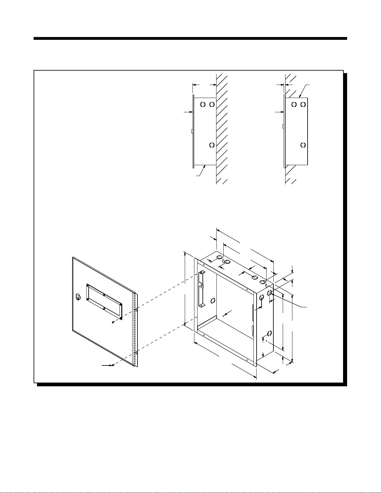
TRugged,keylocked, redcabinetwith tencombinationknockouts, easilyremoveablepiano hingeddoorand
an integrated trim “ring” for surface or flush mounted installation. Uses Gamewell Key.
Technical Manuals Online! - http://www.tech-man.com
firealarmresources.com

Page 5 of 35
2.0 GENERAL NOTES and DEFINITIONS
Circuits and Zones:
“Circuits” refers to an actual electrical interface, Initiating (Detection), Indicating (Notification), or Relay.
“Zone” is a logical concept for a Fire Alarm Protected Area, and will consist of at least one Circuit.
Often the terms Zone and Circuit are used interchangeably, but in this Manual the term Circuit is used.
Terminology:
“Indicating Circuits” are also know as Notification Appliance Circuits, Signal Circuits and Bell Circuits.
Wiring Styles:
Initiating Circuits are configured by default as Class B (Style B). They may be GLOBALLY (all or none) configured
as Class A (Style D) as described in the Configuration Section. This operation uses odd and even pairs of two-wire
Class B (Style B) circuits to make one four-wire Class A (Style D) circuit, thus halving the number of available
Initiating Circuits.
Indicating Circuits may be individually wired as Class A (Style Z) or Class B (Style Y) without affecting the number
of circuits available (see Module wiring instructions).
Technical Manuals Online! - http://www.tech-man.com
firealarmresources.com

Page 6 of 35
3.0 SYSTEM COMPONENTS
Model: Flex 4 & Flex 8 Fire Alarm Control
Model: CEM Circuit Expander Module
Model: PRM PolarityReversal/CityTieModule
Model: DACT Digital Communicator Module
Model: RY4 & RY8 4 & 8 Relay Module
Technical Manuals Online! - http://www.tech-man.com
firealarmresources.com

Page 7 of 35
3.1 MODELS
Model: Flex 4 Fire Alarm Control Panel with four Class B (Style B) or two Class A (Style D) Initiating Circuits,
andtwoPower LimitedClassA/B(StyleZ/Y) IndicatingCircuits(maximum1.70amperes each,
5amperes total) with individual trouble indicators. Common Alarm & Trouble Relays. Interface
for Remote Trouble Indicator RTI and/or 1 to 3 of RA8 Remote Multiplex Annunciators.
Resettable Power Supply for Four Wire Smoke or Heat Detectors . May have one DACT or
PRM, and one CEM installed. May also have one of RY4 or RY8 installed.
Model: Flex 8 FireAlarm ControlPanel witheight ClassB (StyleB)orfourClass A(Style D) Initiating Circuits,
andfourPowerLimitedClassA/B(StyleZ/Y)IndicatingCircuits(maximum1.70ampereseach,
5amperes total) with individual trouble indicators. Common Alarm & Trouble Relays. Interface
for Remote Trouble Indicator RTI and/or 1 to 3 of RA8 Remote Multiplex Annunciators.
Resettable Power Supply for Four Wire Smoke or Heat Detectors May have one DACT or
PRM, and one CEM installed. May also have one of RY4 or RY8 installed.
Model: CEM Circuit Expander Module for the Flex 4 to increase the system capacity to that of the Flex 8.
Model: RY4 Relay Module for Flex 4 or Flex 8. Adds four configurable Relays Form C rated 1A, 28 VDC.
Model: RY8 Relay Module for Flex 4 or Flex 8.Adds eight configurable Relays Form C rated 1A, 28 VDC.
Model: DACT Dual Line Digital Alarm Communicator Transmitter Module.
Model: PRM City Tie / Reverse Polarity Module.
3.2 ACCESSORIES
Model: RA8 8 Zone Remote Annunciator (UL Listed)
Model: RTI Remote Trouble Indicator (UL Listed)
Model: 30177 End of Line Resistor (UL Listed)
Model: CFG DACT programming tool
3.3 BATTERIES
Model: B12V4 12 Volt 4 Ampere-Hour (2 required)
Model: B12V7 12 Volt 7 Ampere-Hour (2 required)
Model: B12V12 12 Volt 10 Ampere-Hour (2 required)
Technical Manuals Online! - http://www.tech-man.com
firealarmresources.com

Page 8 of 35
FINISH: PAINTED
DOOR 16GA (0.059") THICK
COLD ROLLED STEEL
DOOR
BACKBOX
(SIDE VIEW)
SURFACE
DOOR
4
5"
1
-
BACKBOX
(SIDE VIEW)
FLUSH
BACKBOX
DOOR
-
16
5"
WALL WALL
32
"
-
7DIA.
HOLE
"
7
8
15-
16 "
5
16
-
14
-
3"
11"
"
-
1
2
14
1"
"
5
"
"
-
4
3
12
11
-
"
-
7
8
14
1
-
8
1"&"
7
8
-
KNOCKOUT
-
122
1"
8
3
-
1"
2"
8
3"
4-
2"
#6 x 5/16" SCREW
MATERIAL: BACKBOX 18GA (0.048") THICK
Fig.1: Flex 4 and Flex 8 Enclosure Installation and Dimensions
4.0 MECHANICAL INSTALLATION and DIMENSIONS
Install the enclosure as shown below for the Flex 4 and Flex 8...
Technical Manuals Online! - http://www.tech-man.com
firealarmresources.com

Page 9 of 35
(MODEL DACT)
DIALER MODULE
(MODEL PRM)
POLARITY REVERSAL AND
CITY TIE MODULE
M/F HEX SPACER
#6-32 x 7/8"
SCREW
#6-32 x 1/4"
DISPLAY
PLATE
BACKBOX
CIRCUIT
EXPANDER
MODULE
(CEM)
MAIN FIRE
ALARM
MODULE
RELAY MODULE
(NOTE 1)
NOTES:
1. RELAY MODULE MAY BE RY4 OR RY8
2. ONLY ONE OF DACT OR PRM MAY BE INSTALLED
Fig.2: Flex 4 & Flex 8 Module Mounting Locations
5.0 MODULES MOUNTING LOCATIONS
The Flex 4 and Flex 8 come pre-assembled with all components and boards, except for the following optional
modules; DACT,PRM,RY4,RY8 or the CEM when field installed to increase the circuits available with theFlex 4.
The modules are installed in the locations shown below.
Be sure to connect a solid Earth Ground (from building system ground / to a cold water pipe) to the Chassis Earth
Ground Mounting Lug, and to connect the Earth Ground Wire Lugs from the Main Chassis to the ground screw on
the back box.
Technical Manuals Online! - http://www.tech-man.com
firealarmresources.com

Page 10 of 35
6.0 MODULE SETTINGS
6.1 MAIN FIRE ALARM MODULE
Class A / B Selection: JW1 &JW2 are connected from 1 to 2 for Initiating CircuitClass B (Style B) operation, and from 2 to 3 for Class
A (Style D) operation.
Note that the Class A/B selection affects all Initiating Circuits, and must be used with the correct Configuration DIP Switch Setting.
Circuit Expander On an Flex 4 only, remove the jumper on JW4 if a CEM Circuit Expander Module is field installed. The module
Module: is plugged into P6 & P7.
Relay Module: Remove jumper JW3 if a RY4 or RY8 Relay Module is installed. The Relay Module is plugged into P1.
Digital Communicator: Remove jumper JW6 if a DACT Digital Communicator is installed. The Digital Communicator is plugged into P8.
City Tie: Remove jumper JW6 if a PRM Polarity Reversal/City Tie module is installed. The module is plugged into P8.
Battery: Connected to P2 (+’ve) &P3 (-’ve) via the factory installed cables.
Transformer: Factory wired to P4 &P5, do not disconnect.
JW5 There should be no jumper here; do not use.
SW9, SW11, SW13 Configuration DIP Switches.
Battery Fuse F1: Replace with 10 Amp, 1-1/4" Fast Acting Fuse
Technical Manuals Online! - http://www.tech-man.com
firealarmresources.com

Page 11 of 35
Fig.3: Main Fire Alarm Module
Fig.4: CEM Circuit Expander Module
6.2 CIRCUIT EXPANDER MODULE (Model CEM)
Class A / B Selection: JW2 & JW3
are connected from 1 to 2 for Initiating
Circuit Class B (Style B) operation,
and from 2 to 3 for Class A (Style D)
operation.
Note that the Class A/B selection
affects all Initiating Circuits, and
must be used with the correct
Configuration DIP Switch Setting.
P1 &P2: Connections to P7 & P6
respectively on the Main
Fire Alarm Board.
SW5,6: ConfigurationDIPSwitches.
Technical Manuals Online! - http://www.tech-man.com
firealarmresources.com

Page 12 of 35
Fig.5: RY4 or RY8 Auxiliary Relay Module
6.3 RELAY MODULES (Models RY4 or RY8)
P1 Connect to P1 on the Main
Fire Alarm Board.
By the factory setting, the 4 or 8
relays are controlled by Initiating
Circuits 1 to 8 respectively. This is
configured by selecting ...
JW1 Initiating Circuit #1 controls
Relay #1.
JW2 Initiating Circuit #2 controls
Relay #2.
|
|
JW8 Initiating Circuit #8 controls
Relay #8.
Alternatively, each relay may be set
as a Common Alarm or Common
Supervisory Relay by moving the
jumper from JW1 to JW1A, etc.
These jumpers have two positions to
select Alarm or Supervisory each.
JW1A Alarm or Supv. control for
Relay #1.
JW2A Alarm or Supv. control for
Relay #2.
|
|
JW8A Alarm or Supv. control for
Relay #8.
Finally, there are jumpersJW1.2,JW2.3,up toJW7.8 that allow a relay to have the same control as an adjacent relay. For example, starting with
the factory default setting, moving the jumper from JW2 to JW1.2 will make both Relays 1 & 2 operate with Initiating Circuit #1.
Contact GAMEWELL Technical Services for assistance if required.
Technical Manuals Online! - http://www.tech-man.com
firealarmresources.com

Page 13 of 35
Fig.6: DACT Digital Alarm Communicator Transmitter Module
Fig.7: PRM City Tie Module
6.4 DIGITIAL ALARM COMMUNICATOR MODULE (Model DACT)
P1 Cable to P8 on the Main Fire
Alarm Board.
Jumper JW6 on the Main Fire Alarm
Module must be removed if aDACT is
installed.
Note that this module cannot be
installed if a PRM (Polarity
Reversal/City Tie Module) is used.
Please see the DACT Installation
instructions for more information.
6.5 POLARITY REVERSAL and CITY TIE MODULE (MODEL: PRM)
P1 Cable to P8 on the Main Fire
Alarm Module.
JW1Cut this jumper for Trouble
transmission. When this jumper
is cut and a system trouble
occurs,thedesignatedterminals
will transmit a "zero volts" or
"open" circuit. Please note that
at normal condition, the
terminals polarity is read exactly
as labelled on the circuit board.
Jumper JW6 on the Main Fire Alarm
Module must be removed if a City Tie
Module is installed.
Note that this module cannot be
installed if a DACT module is used.
Technical Manuals Online! - http://www.tech-man.com
firealarmresources.com

Page 14 of 35
USE AT LEAST
3 WIRE TIES
AS SUPPLIED
THROUGH HOLES
ON DEADFRONT
WIRE TIE
IN 2 PLACES
TO BACK OF
ENCLOSURE
DRESS WIRES NEAR
TOP OF ENCLOSURE
CLEAR OF ADDER
MODULES
Fig.8: General Field Wiring Considerations
7.0 MODULE FIELD WIRING
7.1 GENERAL FIELD WIRING CONSIDERATIONS
Becausemostof theField WiringontheFlex 4 andFlex 8 isto theMainBoard(s)on theswingingDeadFrontpanel,
it is very important to properly dress the wires so as not to place stress on either their connection to the boards, or
running to conduit. The figure below shows the required wiring techniques.
Technical Manuals Online! - http://www.tech-man.com
firealarmresources.com

Page 15 of 35
Fig.9: Main Fire Alarm Module Terminal Connections
CLASSA/ STYLE DNOTE:INITIATINGCIRCUITS MUST
ALL BE EITHER STYLE B OR D. IF STYLE D IS
SELECTED, THE NUMBER OF CIRCUITS IS CUT IN
HALF. (i.e. 2 ON A FLEX 4 AND 4 ON A FLEX 8)
7.2 MAIN FIRE ALARM MODULE TERMINAL CONNECTIONS
Wire devices to terminals as shown. See wiring tables and Appendix A for compatible devices and Appendix C for specifications.
Caution: Do not exceed power supply ratings: Total current for Indicating Circuits is 5 A max.
Technical Manuals Online! - http://www.tech-man.com
firealarmresources.com

Page 16 of 35
Fig.9a: Main Fire Alarm Module Terminal Connections (continued)
Technical Manuals Online! - http://www.tech-man.com
firealarmresources.com

Page 17 of 35
Fig.10: CEM Circuit Expander Module Terminal Connections
CLASS A / STYLE D NOTE: INITIATING CIRCUITS MUST ALL
BE EITHER STYLE B OR D. IF STYLE D IS SELECTED, THE
NUMBER OF CIRCUITS IS CUT IN HALF. (i.e. 2 ON A FLEX 4
AND 4 ON A FLEX 8)
7.3 CIRCUIT EXPANDER MODULE (CEM) TERMINAL CONNECTIONS
Initiating circuits 5 through 8 and Indicating circuits 3 and 4 are standard with the Flex 8 Control Panel. A Flex 4 Control Panel may be easily
expanded to 8 initiating circuits and 4 indicating circuits with the field installation of a Circuit Expander Module (CEM). When configured for Class
“A”wiringperformance,thecontrolwill provide four initiatingcircuits.Allcircuitsmaybeusedfornormalorverifiedalarmoperationorcircuitsthree
and four may be configured for Waterflow alarm and Supervisory Service respectively.
Wire devices to terminals as shown. See wiring tables and appendix "A" for compatible devices. See appendix "C" for Module specifications.
Technical Manuals Online! - http://www.tech-man.com
firealarmresources.com

Page 18 of 35
7.4 RELAY MODULE (RY4 or RY8) TERMINAL CONNECTIONS
Note that only Relays #1 to #4 are present on the RY4.
Fig.11: RY4 / RY8 Relay Terminal Connections
Technical Manuals Online! - http://www.tech-man.com
firealarmresources.com

Page 19 of 35
Fig.12: PRM Polarity Reversal and City Tie Module Terminal Connections
7.5 DACT / DIGITAL ALARM COMMUNICATOR MODULE TERMINAL CONNECTIONS
For DACT connection information, see the Installation Instruction Manual Part Number 71954-01.
7.6 POLARITY REVERSAL and CITY TIE MODULE (MODEL: PRM) TERMINAL CONNECTIONS
See Appendix for Module specifications. Wire as shown using proper wire gauges.
Note that for use in the USA, the installer MUST add an Atlantic Scientific (Tel. 407-725-8000) Model #24544
Protective Device, or a similar UL Listed QVRG Secondary Protector, as shown.
Note: The Terminal Blocks are “pluggable” for ease of wiring.
The City Tie Interface is Not Power Limited.
Either the City Tie or Reverse Polarity Interface may be used, but not both.
Technical Manuals Online! - http://www.tech-man.com
firealarmresources.com

Page 20 of 35
Fig.13: Power Supply Connections
7.7 POWER SUPPLY CONNECTIONS
The power supply is an integral part of the Main Fire Alarm Module and the Chassis. The ratings for the supply are:
Flex 4 and Flex 8:
Electrical input ratings: 120 VAC, 60 Hz, 2 A main primary circuit breaker
Power supply total current: 6 A maximum
Battery Fuse on Main Module: F1: Replace with 10 Amp, 1-1/4" Fast Acting Fuse
CAUTION: Do not exceed power supply ratings.
See appendix "C" for specifications. Wire as shown using proper wire gauges.
Technical Manuals Online! - http://www.tech-man.com
firealarmresources.com
This manual suits for next models
1
Table of contents
Other Gamewell Fire Alarm manuals
Popular Fire Alarm manuals by other brands

Wheelock
Wheelock RSS-24MCW installation instructions

Tyco Fire Product
Tyco Fire Product TY-B Series quick start guide

SILENT KNIGHT
SILENT KNIGHT INTELLIKNIGHT 5820XL Installation and operation manual

Siemens
Siemens FC700A System planning

olympia electronics
olympia electronics BSR-100 MAR Series Installation, Programming Operation, & Maintenance Manual

Honeywell
Honeywell Notifier FAAST LT NFXI-ASD Series Quick installation guide