manuals.online logo
Brands
  1. Home
  2. •
  3. Brands
  4. •
  5. Hochiki
  6. •
  7. Security Sensor
  8. •
  9. Hochiki YBO-BS User manual

Hochiki YBO-BS User manual

INSTALLATION INSTRUCTIONS FOR HOCHIKI ANALOGUE SENSORS
TYPE: ACC, ATJ, ALN
INTRODUCTION
Analogue Multi sensor ACC-ASN
Analogue Heat sensor ATJ-ASN
Analogue Smoke sensor ALN-ASN
Analogue Sensor Base YBN-R/3, YBN-R/3(SCI), YBO-R/SCI,
YBO-BS, YBO-BSB, YBO-BSB2
Other combinations of sensor and base are also possible.
Please confirm with Hochiki or the appointed sales agent.
Ensure that the following items are inspected before installation and maintenance.
Hochiki cannot warrant a sensor’s performance if such items are neglected.
CAUTION
・This sensor cannot be used to prevent FIRE itself, it is only intended to detect a certain characteristic of fire.
・When installing this sensor, ensure that the location of each sensor has been planned in accordance with appropriate local
and National fire regulations or recommendations.
・The detector shall not be installed in the following environmental conditions:
-Situations in which condensation exists.
-Situations in which corrosive gases exist.
-Situations in which dust or steam exist.
-Situations in which obstacles exist, which could impede airflow to the detector.
・Certain actions can cause permanent damage to the sensor and therefore if the sensor is subjected to any of the following
actions it should not be used:
-Disassembly and reassembly.
-Impact or shock or drop.
-Touching the thermistors of the sensor(the thermistors is orange color and located in sides of smoke chamber). (only
ACC and ATJ)
・The sensor should therfore be replaced after a fire has occurred if damage is suspected.
・After installation, all sensors on the fire alarm system should be tested to verify correct operation.
・Installation and maintenance should only be carried out by suitably trained personnel.
・The sensor must be subject to periodic maintenance during regular service visits, which should be as recommended by
appropriate local and National Standards or recommendations. In the event of no such Standards existing, Hochiki
recommend that the minimum period of maintenance should be 1 year and that the following items should be taken into
account:
-In cases where there are excess built up of dust on the smoke chamber or the thermistors, the sensitivity of the sensor
could be affected.
-A regular operational test should be performed.
-A visual check for staining and mechanical damage should be made.
-If the Testifire, Solo or an equivalent heat detector tester is being used to test the ACC/ATJ, please ensure that the
main duct of the tester is aligned with one of the thermistors on the sensor, incorrect alignment could result in a
failed test or damage to the sensor.
・Sensor operation should not be verified by the use of a naked flame or open fire.
Operation should only be checked by equipment that is capable of exceeding the required detection threshold by a small
amount sufficient to guarantee a fire signal is produced by the sensor.
・A dust cover is included on the sensor to ensure that contamination cannot affect the correct operation for the sensor. The dust
cover must be removed for the sensor to operate. (only ACC and ALN)
・The correct operation and function for each sensor must be checked during installation. Regular checks of each device's
operation should be made to ensure that the system continues to operate correctly.
・Compliance with AS 7240.5 and 7240.7 is achieved at Table.1 setting. Other settings do not comply with AS 7240.5 and AS
7240.7.
EXTERNAL VIEW
REF.No.:7-0-000-3207-722
Fig.1
SMALLER HOLE
ACC:DOUBLE
ALN:NO CIRCLE
LAGER HOLE
SMOKE CHAMBER(ACC/ALN)
THERMISTOR(ACC/ATJ)
CONTACT BLADE
NAME LABEL
PRONG
MARKING
ATJ:SINGLE
SETTING THE ADDRESS
・Each sensor must have it’s address set before system operation.
・Using the installation plan which shows the proper location for each sensor, find the address for the sensor to be installed.
Ensure that the address and location on the plan match correctly.
・Address is set to 127,when shipping from a factory.
・For address setting, use the address programmer and write the number on the label of the sensor after setting.
・Address must be set within the address setting range of the connected panel.
・When address changing, renew the number on the label.
・See the instruction manual of the Hand Held programmer(TCH-B100/TCH-B200) about detail of setting method.
WIRING
The wiring diagram for the analogue sensor base should be made as shown in Fig. 2.
Fig.2
HOW TO USE OF SENSOR HEAD REMOVER
1) In case of sensor head mounting to the base.
a) Adjust the remover for sensor sizes.
b) Grip sensor and push the sensor to the sensor base softly.
c) Twist clockwise for secure fitting of the sensor head and base.
2) In case of sensor removal from the base.
a) Adjust the remover for sensor sizes.
b) Grip sensor, twist counterclockwise and pull down for removal of the sensor head from the base.
HOW TO USE THE TAMPER LOCK OF THE SENSOR
1) Take any sensor and turn it over to view the bottom as shown in Fig. 3.
2) Using a small slot type screw driver break the prong as shown in Fig. 4.
3) Mount the sensor to the base bringing seams of the sensor and base into line for secure tamper locking (see Fig. 5).
HOW TO REMOVE THE TAMPER LOCKED SENSOR
1) Take a small slot screw driver and insert it into the larger hole on the outer rim of the sensor (see Fig. 6).
2) While pushing the tab down rotate the sensor counter clockwise enough to clear the base security locking tab.
Only use enough force to remove the sensor.
CAUTION: DO NOT USE EXCESSIVE FORCE WHEN UNLOCKING THE BASE SECURITY LOCKING TAB
SETTING THE SENSITIVITY
Please use mode of built in class setting, if panel has setting of class.
Table.1
Model Name Smoke
Heat
Class Setting Class Setting Class Setting
ACC-ASN 2.0-4.5%/m A1 Fixed Temperature 60℃- - C
Fixed Temperature 88℃
ATJ-ASN -
A1 Fixed Temperature 60℃B Fixed Temperature 78℃C Fixed Temperature 88℃
A1R Fixed Temperature 60℃BR Fixed Temperature 78℃CR Fixed Temperature 88℃
A1S Fixed Temperature 60℃BS Fixed Temperature 78℃CS Fixed Temperature 88℃
ALN-ASN 2.0-4.5%/m -
SMALL SLOT TYPE
SCREW DRIVER
PRONG
This will prevent the sensor
from being removed from the base
BASE SECURITY
LOCKING TAB
Insert small slot type screw driver
into larger hole in a sensor to
release locking tab on base
Fig.3 Fig.4 Fig.5 Fig.6
*Optional wiring configurations for remote output
Voltage: 17 to 40V
Current: 8.0mA±20%
LOOP
OUT
POWER
LINE
PANEL
Next
Sensor
to
LOOP IN

Other manuals for YBO-BS

2

This manual suits for next models

8

Other Hochiki Security Sensor manuals

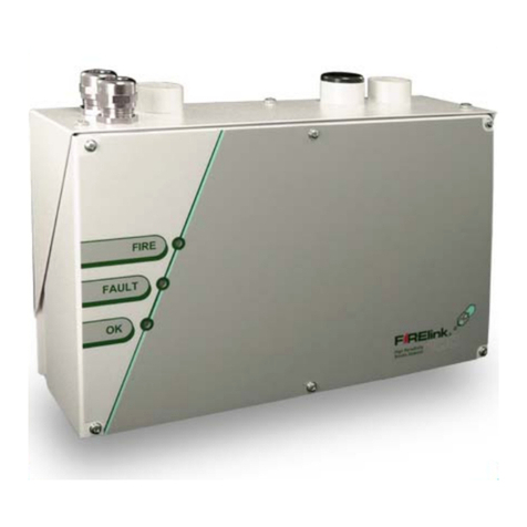
Hochiki FIRElink-25 User manual

Hochiki

Hochiki FIRElink-25 User manual

Hochiki IFD-E(Exd) User manual

Hochiki

Hochiki IFD-E(Exd) User manual

Hochiki SPC-ET Instruction Manual

Hochiki

Hochiki SPC-ET Instruction Manual

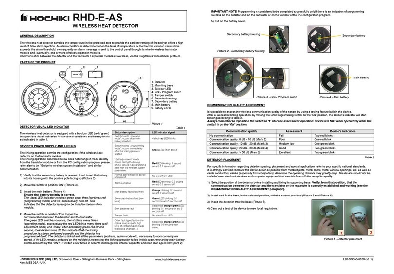
Hochiki RHD-E-AS User manual

Hochiki

Hochiki RHD-E-AS User manual

Hochiki FIRElink-100 User manual

Hochiki

Hochiki FIRElink-100 User manual

Hochiki IFD-E User manual

Hochiki

Hochiki IFD-E User manual

Hochiki DH-100-P User manual

Hochiki

Hochiki DH-100-P User manual

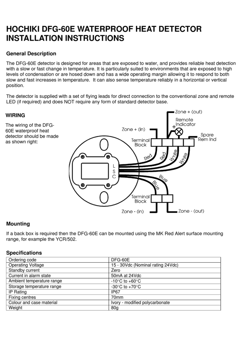
Hochiki DFG-60E User manual

Hochiki

Hochiki DFG-60E User manual

Hochiki SPC-E Installation instructions manual

Hochiki

Hochiki SPC-E Installation instructions manual

Popular Security Sensor manuals by other brands

Emerson MRLDS-250 Quick setup guide

Emerson

Emerson MRLDS-250 Quick setup guide

Buchi Alltech 3300 ELSD Operation manual

Buchi

Buchi Alltech 3300 ELSD Operation manual

FujiFilm PL-G.MAX Operation manual

FujiFilm

FujiFilm PL-G.MAX Operation manual

B.E.G. MINI-S-PP-FC Installation and operating instruction

B.E.G.

B.E.G. MINI-S-PP-FC Installation and operating instruction

INIM qtech QDT500H Installation and programming manual

INIM

INIM qtech QDT500H Installation and programming manual

Omron F3SP-U4P-TGR user manual

Omron

Omron F3SP-U4P-TGR user manual

Elcometer 136 operating instructions

Elcometer

Elcometer 136 operating instructions

Protekt CR 240 Series instruction manual

Protekt

Protekt CR 240 Series instruction manual

Seres OL PAUTBAC II User and maintenance manual

Seres OL

Seres OL PAUTBAC II User and maintenance manual

US Netting Defender Gate 20 instruction manual

US Netting

US Netting Defender Gate 20 instruction manual

Lena Lighting Dual Sense WSED414 manual

Lena Lighting

Lena Lighting Dual Sense WSED414 manual

Pepperl+Fuchs INX360D-F99-I2E2-V15 manual

Pepperl+Fuchs

Pepperl+Fuchs INX360D-F99-I2E2-V15 manual

Hytronik Dual Sense HIM14 quick start guide

Hytronik

Hytronik Dual Sense HIM14 quick start guide

AccuBANKER D700 user guide

AccuBANKER

AccuBANKER D700 user guide

Mosentek MS033C manual

Mosentek

Mosentek MS033C manual

Tractel Tracpode Operating and maintenance instructions

Tractel

Tractel Tracpode Operating and maintenance instructions

Visonic DA-5 installation instructions

Visonic

Visonic DA-5 installation instructions

Hytronik HIR21 quick start guide

Hytronik

Hytronik HIR21 quick start guide

manuals.online logo
manuals.online logoBrands
  • About & Mission
  • Contact us
  • Privacy Policy
  • Terms and Conditions

Copyright 2025 Manuals.Online. All Rights Reserved.