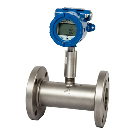
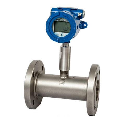
Hoffer Flow Controls HIT-2A User manual

H
offer Intelligent
R
ate Indicator & Totalizer
M
odel: HIT-2A
HP-306
November 2009
107 Kitty Hawk Lane, P.O. Box 2145, Elizabeth City, NC 27906-2145
800-628-4584 252-331-1997 FAX 252-331-2886
www.hofferflow.comE-mail: info@hofferflow.com
USER’S MANUAL
Model: HIT-2A
Hoffer Intelligent
Rate Indicator & Totalizer
USER’S MANUAL
HP-306
October 2013


HFC 9907-A
HOFFER FLOW CONTROLS, INC. makes no warranty of any
kind with regard to this material, including, but not limited to,
the implied warranties of merchantability and fitness for a
particular purpose.
This manual has been provided as an aid in installing, connecting,
calibrating, operating, and servicing this unit. Every precaution for
accuracy has been taken in the preparation of this manual;
however, HOFFER FLOW CONTROLS, INC. neither assumes
responsibility for any omissions or errors that may appear nor
assumes liability for any damages that may result from the use
of the products in accordance with information contained in the
manual.
HOFFER FLOW CONTROLS' policy is to provide a user
manual for each item supplied. Therefore, all applicable user
manuals should be examined before attempting to install or
otherwise connect a number of related subsystems.
During installation, care must be taken to select the correct
interconnecting wiring drawing. The choice of an incorrect
connection drawing may result in damage to the system and/or one
of the components.
Please review the complete model number of each item to be
connected and locate the appropriate manual(s) and/or drawing(s).
Identify all model numbers exactly before making any connections.
A number of options and accessories may be added to the main
instrument, which are not shown on the basic user wiring. Consult
the appropriate option or accessory user manual before connecting
it to the system. In many cases, a system wiring drawing is
available and may be requested from HOFFER FLOW
CONTROLS.
This document contains proprietary information, which is
protected by copyright. All rights are reserved. No part of this
document may be photocopied, reproduced, or translated to
another language without the prior written consent of HOFFER
FLOW CONTROLS, INC.
HOFFER FLOW CONTROLS’ policy is to make running
changes, not model changes, whenever an improvement is
possible. This affords our customers the latest in technology
and engineering. The information contained in this document is
subject to change without notice.
Return Requests / Inquiries
Direct all warranty and repair requests/inquiries to the Hoffer Flow Controls Customer
Service Department, telephone number (252) 331-1997 or 1-800-628-4584. BEFORE
RETURNING ANY PRODUCT(S) TO HOFFER FLOW CONTROLS, PURCHASER
MUST OBTAIN A RETURNED MATERIAL AUTHORIZATION (RMA) NUMBER
FROM HOFFER FLOW CONTROLS’ CUSTOMER SERVICE DEPARTMENT (IN
ORDER TO AVOID PROCESSING DELAYS). The assigned RMA number should then
be marked on the outside of the return package and on any correspondence.
FOR WARRANTY RETURNS, please
have the following information available
BEFORE contacting HOFFER FLOW
CONTROLS:
1. P.O. number under which the
product was PURCHASED,
2. Model and serial number of the
product under warranty, and
3. Repair instructions and/or specific
problems relative to the product.
FOR NON-WARRANTY REPAIRS OR
CALIBRATIONS, consult HOFFER FLOW
CONTROLS for current repair/ calibration
charges. Have the following information
available BEFORE contacting HOFFER
FLOW CONTROLS:
1. P.O. number to cover the COST of the
repair/calibration,
2. Model and serial number of the
product and
3. Repair instructions and/or specific
problems relative to the product.
NOTICE

HFC 9907-A
LIMITED WARRANTY
HOFFER FLOW CONTROLS, INC. ("HFC") warrants HFC's products ("goods")
described in the specifications incorporated in this manual to be free from defects in
material and workmanship under normal use and service, but only if such goods have
been properly selected for the service intended, properly installed and properly
operated and maintained. This warranty shall extend for a period of one (1) year from
the date of delivery to the original purchaser (or eighteen (18) months if the delivery to
the original purchaser occurred outside the continental United States). This warranty
is extended only to the original purchaser ("Purchaser"). Purchaser's sole and
exclusive remedy is the repair and/or replacement of nonconforming goods as
provided in the following paragraphs.
In the event Purchaser believes the goods are defective, the goods must be returned to
HFC, transportation prepaid by Purchaser, within twelve (12) months after delivery of
goods (or eighteen (18) months for goods delivered outside the continental United
States) for inspection by HFC. If HFC's inspection determines that the workmanship
or materials are defective, the goods will be either repaired or replaced, at HFC's sole
determination, free of additional charge, and the goods will be returned, transportation
paid by HFC, using the lowest cost transportation available.
Prior to returning the goods to HFC, Purchaser must obtain a Returned Material
Authorization (RMA) Number from HFC's Customer Service Department within 30
days after discovery of a purported breach of warranty, but no later than the warranty
period; otherwise, such claims shall be deemed waived. See the Return
Requests/Inquiries Section of this manual.
If HFC's inspection reveals the goods are free of defects in material and workmanship
or such inspection reveals the goods were improperly used, improperly installed,
and/or improperly selected for service intended, HFC will notify the purchaser in
writing and will deliver the goods back to Purchaser upon (i) receipt of Purchaser's
written instructions and (ii) the cost of transportation. If Purchaser does not respond
within thirty (30) days after notice from HFC, the goods will be disposed of in HFC's
discretion.
HFC does not warrant these goods to meet the requirements of any safety code of any
state, municipality, or other jurisdiction, and Purchaser assumes all risk and liability
whatsoever resulting from the use thereof, whether used singly or in combination with
other machines or apparatus.
This warranty shall not apply to any HFC goods or parts thereof, which have been
repaired outside HFC's factory or altered in any way, or have been subject to misuse,
negligence, or accident, or have not been operated in accordance with HFC's printed
instructions or have been operated under conditions more severe than, or otherwise
exceeding, those set forth in the specifications for such goods.
THIS WARRANTY IS EXPRESSLY IN LIEU OF ALL OTHER
WARRANTIES, EXPRESSED OR IMPLIED, INCLUDING ANY IMPLIED
WARRANTY OF MERCHANTABILITY OR FITNESS FOR A PARTICULAR
PURPOSE. HFC SHALL NOT BE LIABLE FOR ANY LOSS OR DAMAGE RESULTING,
DIRECTLY OR INDIRECTLY, FROM THE USE OR LOSS OF USE OF THE GOODS. WITHOUT
LIMITING THE GENERALITY OF THE FOREGOING, THIS EXCLUSION FROM LIABILITY
EMBRACES THE PURCHASER'S EXPENSES FOR DOWNTIME OR FOR MAKING UP
DOWNTIME, DAMAGES FOR WHICH THE PURCHASER MAY BE LIABLE TO OTHER
PERSONS, DAMAGES TO PROPERTY, AND INJURY TO OR DEATH OF ANY PERSONS. HFC
NEITHER ASSUMES NOR AUTHORIZES ANY PERSON TO ASSUME FOR IT ANY OTHER
LIABILITY IN CONNECTION WITH THE SALE OR USE OF HFC'S GOODS, AND THERE ARE
NO ORAL AGREEMENTS OR WARRANTIES COLLATERAL TO OR AFFECTING THE
AGREEMENT. PURCHASER'S SOLE AND EXCLUSIVE REMEDY IS THE REPAIR AND/OR
REPLACEMENT OF NONCONFORMING GOODS AS PROVIDED IN THE PRECEDING
PARAGRAPHS.HFC SHALL NOT BE LIABLE FOR ANY OTHER DAMAGES WHATSOEVER
INCLUDING INDIRECT,INCIDENTAL,OR CONSEQUENTIAL DAMAGES.
Disclaimer
Specifications are subject to change without notice.
Some pages are left intentionally blank.
HP-306
CONTENTS
1. Introduction --------------------------------------------------------------- 1
1-1 Model Number Designation ---------------------------------------- 2
2. SPECIFICATIONS ------------------------------------------------------ 3
2-1 General ---------------------------------------------------------------- 3
2-2 Inputs ------------------------------------------------------------------ 3
2-3 Battery Powered Version ------------------------------------------- 4
2-4 DC Power/Loop Powered------------------------------------------- 4
2-5 AC Power ------------------------------------------------------------- 4
2-6 Analog (4-20mA) Output Option ---------------------------------- 4
2-7 Pulse Output Option ------------------------------------------------- 5
2-8 Alarm Output Option ------------------------------------------------ 5
2-9 Physical --------------------------------------------------------------- 5
3. Theory of Operation ----------------------------------------------------- 7
3-1 Functional Blocks---------------------------------------------------- 7
3-1-1 User Interface--------------------------------------------------- 7
3-1-2 Preamplifier----------------------------------------------------- 7
3-1-3 Microcontroller------------------------------------------------- 7
3-1-4 Loop Driver----------------------------------------------------- 8
3-1-5 Pulse and Alarm Output--------------------------------------- 8
3-1-6 Communications Interface ------------------------------------ 9
3-2 System Response Time---------------------------------------------- 9
4. Installation----------------------------------------------------------------11
4-1 Typical Input Connections----------------------------------------- 11
4-2 Typical Output Connections--------------------------------------- 14
4-3 Communications Connections------------------------------------- 17
4-4 Wiring ---------------------------------------------------------------- 17
4-5 Terminal Designations --------------------------------------------- 17
5. Configuration ------------------------------------------------------------19
5-1 Local Configuration ------------------------------------------------ 19
5-2 Default Configuration ---------------------------------------------- 22
5-3 Remote Configuration---------------------------------------------- 22
6. Operation and Maintenance-------------------------------------------23
6-1 Operation------------------------------------------------------------- 23
6-2 Maintenance --------------------------------------------------------- 24
6-3 Error Messages ------------------------------------------------------ 24
6-4 Analog Output Calibration----------------------------------------- 25
Appendix A – Default Configuration--------------------------------------27
Appendix B - Communications ---------------------------------------------29
Message Format And Timeout --------------------------------------------- 29
Messages ---------------------------------------------------------------------- 31

HP-306

Introduction 1
HP-306
1. INTRODUCTION
The HIT-2A is a microprocessor-based flow rate indicator and totalizer.
The instrument displays flowrate and a resettable total and is
compatible with all Hoffer turbine flowmeters and the H.O.G. series
positive displacement flowmeters.
The instrument can accept a low level frequency signal, a pulse signal,
or a contact closure on the input and provides a linearized rate
indication and total.
The HIT-2A is fully configurable with K-factors, frequencies, and
timebase being configured via the front panel key switches or the
RS232 communications port. The configuration and monitoring can be
performed using any PC based communications program (e.g.,
HyperTerminal) or ASCII terminal.
The instrument is housed in an attractive NEMA 4X polycarbonate
enclosure and can be mounted directly on a flowmeter or wall mounted
using an optional mounting brackets or an EX enclosure.
This instrument has been designed to conform to the EMC-Directive of
the Council of European Communities 89/336/EEC and the following
standards:
Generic Emission Standard EN 61000-6-3
Residential, Commercial & Light Industry Environment.
Generic Immunity Standard EN 61000-6-1
Residential, Commercial & Light Industry Environment.
Electrostatic discharge requirements EN 61000-4-2
Radiated, radio-frequency, electromagnetic immunity EN 61000-4-3
Electrical fast transient/burst requirements EN 61000-4-4
Immunity to conducted disturbances EN 61000-4-6

Introduction 2
HP-306
Model Number Designation
MODEL HIT-2A
TOTALIZER/FLOW RATE INDICATOR
MODEL HIT-2A-( A )-( B )-( C )-( D )-( E )-( F )
ENCLOSURE STYLE
INPUT POWER
LOOP POWERED ANALOG OUTPUT
OPTIONS
MOUNTING
SPECIAL FEATURES
ENCLOSURE STYLE
MODEL HIT-2A-( A )-( )-( )-( )-( )-( )
OPTION ( A )
(2) NEMA 4X ENCLOSURE, HIT-2A MOUNTED BEHIND CLEAR COVER.
(3) EXPLOSION-PROOF ENCLOSURE.
(3A) ATEX Exd ENCLOSURE, STANDARD BLUE.
(3B) ENCLOSURE FOR BRAZIL, GRAY.
(P) PANEL MOUNT - SURFACE MOUNTED ON CUSTOMER’S PANEL;
NO ENCLOSURE BEHIND PANEL ON HIT-2A.
(PD) PANEL MOUNT ENCLOSURE WITH CLEAR DOOR AND LOCK.
(4) NEMA 1 ENCLOSURE (HIT-2A MOUNTED TO THE OUTSIDE OF CLEAR
COVER FOR INDOOR/DRY INSTALLATION ONLY).
(5) NEMA 4X ENCLOSURE/HIT2A ENCLOSURE (MOUNTED BEHIND CLEAR COVER
WITH SUNSHADE.)
(6) EXPLOSION-PROOF ENCLOSURE WITH SUNSHADE.
(6A) ATEX Exd ENCLOSURE, STANDARD BLUE WITH SUNSHADE.
INPUT POWER
MODEL HIT-2A-( )-( B )-( )-( )-( )-( )
OPTION ( B )
(A) INTERNAL BATTERIES (TWO EACH).
THIS OPTION CAN NOT SUPPORT REDI-PULSE COILS.
(B) 8 TO 30 VDC EXTERNAL POWER.
(AC) UNIVERSAL 100-240 VAC @ 0.15A 50/60 HZ.
(X) ENTER (X) IF LOOP POWERED ANALOG OUTPUT OPTION
(C) OR (D) BELOW IS SELECTED.
LOOP POWERED ANALOG OUTPUT
MODEL HIT-2A-( )-( )-( C )-( )-( )-( )
OPTION ( C )
(C) LOOP POWERED 4-20MA OUTPUT (8 TO 30 VDC).
(D) LOOP POWERED 4-20MA OUTPUT WITH INTERNAL BATTERIES.

Introduction 2A
HP-306
OPTIONS
MODEL HIT-2A-( )-( )-( )-( D )-( )-( )
OPTION ( D )
(L) 20 POINT LINEARIZATION.
(RR) REMOTE RESET
(AL) LOW ALARM* OPTO ISOLATED OPEN COLLECTOR.
(AH) HIGH ALARM* OPTO ISOLATED OPEN COLLECTOR.
(HT) HEATER; REQUIRES DC POWER INPUT OPTION.
*NOTE: EITHER LOW OR HIGH ALARM IS AVAILABLE, NOT BOTH.
MOUNTING
MODEL HIT-2A-( )-( )-( )-( )-( E )-( )
OPTION ( E )
(F) NEMA 4X STYLE 2 ENCLOSURE MOUNTED ON TURBINE.
MUST BE USED WITH “X” RISER TURBINE OPTION.
(FHT) 8" LONG TEMPERATURE RISER FOR NEMA 4X STYLE 2
ENCLOSURE MOUNTED ON TURBINE. REQUIRED WHEN
FLUID TEMPERATURES EXCEED 140 DEG. F. USED WITH
“X” RISER TURBINE OPTION.
(FX) EXPLOSION-PROOF STYLE 3 ENCLOSURES MOUNTED ON
TURBINE. MUST BE USED WITH “X” RISER TURBINE OPTION.
(FXHT) 8" LONG TEMPERATURE RISER FOR EXPLOSION-PROOF
STYLE 3 ENCLOSURES MOUNTED ON TURBINE. REQUIRED
WHEN TEMPERATURES EXCEEDS 140 DEG. F. USED WITH
“X” RISER TURBINE OPTION.
(NP) NEMA 4X ENCLOSURE PIPE MOUNTING KIT, 2" PIPE OR SMALLER.
SPECIFY IF PIPE IS VERTICAL OR HORIZINTAL.
SPECIAL FEATURES
MODEL HIT-2A-( )-( )-( )-( )-( )-( F )
OPTION ( F )
(CE) CE MARK REQUIRED FOR EUROPE
(MIL) MIL-S-901D, “SHOCK TESTS, H.I. (HIGH IMPACT) SHIPBOARD
MACHINERY, EQUIPMENT, AND SYSTEMS, REQUIREMENTS FOR;”
DATED 17 MARCH 1989. MIL-STD-167-1, MECHANICAL VIBRATION
OF SHIPBOARD EQUIPMENT (TYPE I – ENVIRONMENTAL & TYPE II –
INTERNALLY EXCITED), 1 MAY 1974.
(SP) ANY SPECIAL FEATURES THAT ARE NOT COVERED IN THE
MODEL NUMBER USE A WRITTEN DESCRIPTION OF THE -SP.
NOTES: 1. OPTO-ISOLATED OPEN COLLECTOR TRANSISTOR IS STANDARD WITH ALL UNITS.
2. A LOCAL RESET MAGNET IS STANDARD WITH ALL UNITS EXCEPT IF REMOTE
RESETOPTION IS SELECTED.
3. WINDOWS® BASED SETUP DISC AND, IF REQUIRED, 6 FT COMMUNICATION
CABLE. IF THREE OR MORE UNITS ARE ORDERED ON THE SAME PURCHASE
ORDER ONE SET IS SUPPLIED AT NO CHARGE.
SPARE OMNICEL MODEL ER26500 OR EQUIVALENT; LITHIUM SIZE C,
BATTERIES 3.6V 8500 mAh (TWO BATTERIES ARE REQUIRED FOR
BATTERY POWERED UNITS. ONE BATTERY IS REQUIRED FOR ALL
OTHER POWER OPTIONS TO RETAIN TOTAL DISPLAY IF POWER
FAILS.

Introduction 2B
HP-306
This page intentionally left blank.

Specification 3
HP-306
2. SPECIFICATIONS
2-1 General
Display: LCD, continuously powered
Total: 8 digits 0.26" high. Resettable from front
panel.
Total Units: GAL, LIT, FT3, M3, BBL, & “blank”.
Rate: 5 digits 0.5" high.
Rate Units: /MIN, /HR, & /DAY
K-factor: The pulses per unit of Total (e.g.
pulses/gallon) are configurable in the range
0.001 to 99,999,999.
Linearization: Up to 20 points.
Decimal Points: Decimal Point positions are fully
configurable for both rate and total.
Accuracy: 0.01% Reading, 1 count
Temperature drift: 50 ppm/°C
2-2 Inputs
Magnetic Pickup:
Frequency Range: 0.2 Hz to 5000 Hz.
Signal Type: Low-level sinusoidal (30 mV P-P minimum).
Opto-Isolated DC Pulse:
Frequency Range: 0 Hz to 3000 Hz.
Signal Type: DC pulse.
High (Logic 1): 4 to 30 VDC
Low (Logic 0): < 1 VDC
Min Current: 0.5 mA
Hystersis: 0.4 VDC
Min Pulse width: 0.1 msec
Contact Closure:
Frequency Range: 0 Hz to 5000 Hz
Signal Type: Contact closure to DC common
High (Logic 1): Open or 4 to 30 VDC
Low (Logic 0): < 0.5 VDC
Internal Pull-up: 220 kΩ to +3.3 VDC

Specification 4
HP-306
Reset:
Signal Type: Contact closure to DC common
High (Logic 1): 4 to 30 VDC
Low (Logic 0): < 0.5 VDC
Min Current: 0.5 mA
Min On: 25 msec
Internal Pull-up: 100 kΩ to +3.3 VDC
External Magnet: Activates internal reed switch
2-3 Battery Powered Version
Type: Two C-size lithium battery packs.
Battery Life: 6 years typical*
10 years typical* for external power.
* With the pulse output OFF. With pulse output ON 30% less.
2-4 DC Power/Loop Powered
Voltage: 8 to 30 VDC
Current: < 4 mA
Loop Burden: 8 VDC maximum
Supply Backup: One (1) C-size Lithium battery
Protection: Reverse polarity protected
2-5 AC Power
Voltage: 100 to 240 VAC
Frequency: 47 – 440 Hz
Current: 150 mA
Line Regulation: 0.3%, typ
Protection: Short circuit, Over voltage, & Over
temperature
Supply Backup: One (1) C-size Lithium battery
2-6 Analog (4-20mA) Output Option
Scale: 4 – 20 mA follows rate.
Accuracy: 0.02% of Full Scale @ 20ºC.
Temperature drift: 40 ppm/°C
Update Time: 2.0 seconds.
Connection: Two wire.
Protection: Reverse polarity protected

Specification 5
HP-306
2-7 Pulse Output Option
Type: Opto-isolated open collector (100 VDC,
100 mA).
Divider: 1, 10, 100, or OFF
Rate & Duration: See below.
SPEED (Hz) 1 2 4 8
Min on/off (msec) 500 250 125 62.5
2-8 Alarm Output Option
Type: Opto-isolated open collector (100 VDC,
100 mA).
Function: Rate or Total
2-9 Physical
Temperature: Operating: -40°F (-40C) to 158 °F (70C)
-58°F (-50C) with optional
heater.
32°F (0°C) to 140 °F (60°C)
with AC power option.
Humidity: 0 – 90% Non-condensing.
Packaging: Wall Mount & Explosion proof
Dimensions for Wall
Mount enclosure:
4.33" (110 mm) wide x 4.33" (110 mm) long
4.33" (110 mm) tall.

Specification 6
HP-306
This page intentionally left blank.

Theory of Operation 7
HP-306
3. THEORY OF OPERATION
The HIT-2A consists of six functional blocks. These functional blocks
are the User Interface, Preamplifier, Microcontroller, Loop Driver,
Pulse and Alarm Output, and Communications Interface.
3-1 Functional Blocks
3-1-1 User Interface
The User Interface consists of a custom LCD display with 4 push
buttons; OK, P, > (right arrow), and ^ (up arrow) and an optional
external reset. Using the buttons and the displayed information,
the user can enter setup parameters (rate units, pulses per unit of
flow, etc.) as well as setup information for the pulse output and 4-
20mA output. The optional external reset maybe used to reset the
accumulated total to zero and clear the displayed accumulated
total.
3-1-2 Preamplifier
The Preamplifier accepts the input from the flowmeter. The
Preamplifier applies amplification, low-pass filtering, and wave-
shaping to the input signal. The wave shaping function converts
the signal into a square-wave before sending it to the
Microcontroller.
3-1-3 Microcontroller
The Microcontroller accepts the square-wave output of the
preamplifier and performs all of the calculations that are required
to control the Loop Driver. After measuring the frequency of the
Flowmeter Input
Microcontroller
Loop Driver 4-20 mA
Pulse Output
Communications
Interface User
Interface
RS232
Preamp Opto-isolated
Outputs
Alarm Output
IRDA

Theory of Operation 8
HP-306
square-wave, the Microcontroller uses the following equations to
compute the flow rate and current.
Where:
Kfactor = Is dependent on the Flow Calculation Method setting
and is either the Average K-Factor or the Linearized
K-Factor from the Frequency / K-Factor table.
FM = Is the Flow rate Units setting of 0, 1, 2 or 3. Where “0” is
for Seconds, “1” is for Minutes, “2” is for Hours and “3”
is for days.
CF = Is the Correction Factor setting.
Where:
AF = is the 20 mA maximum Flow Rate value.
If the calculated flowrate is greater than the AF setting, the
current will be set to 24mA to signal an “Over-range” condition.
After calculating the current, the Microcontroller digitally sends
the current information to the Loop Driver.
3-1-4 Loop Driver
The loop driver uses the digital information received from the
Microcontroller to set the current of the loop. The Loop Driver
supplies power to both the Preamplifier and Microcontroller.
3-1-5 Pulse and Alarm Output
The Pulse and Alarm outputs are two optically isolated open
collector outputs. The alarm output activates when the total flow
or the rate reaches a user defined level. The pulse output activates
to give a scaled pulse output indicative of the total flow. Both of
these outputs are rated for 100 VDC at 100 mA.
xCFx
Kfactor
frequency
flowrate FM
60
AF
flowrate
mAxmAcurrent 164

Theory of Operation 9
HP-306
3-1-6 Communications Interface
The communication is provided through a RS232C interface to
the Microcontroller. The external terminal device provides the
power for the RS232 interface. The Communications Interface is
used to configure and trouble-shoot the device.
3-1-7 Clearing Total
The Total amount stored in HIT-2A memory can be cleared from
the front panel program menu, by external momentary switch
wired to the reset input, or by external magnet. The magnet has to
be brought close to top of the front panel.
3-2 System Response Time
The displayed Rate and Total are updated every two (2) seconds. The
analog output response time to reach steady state due to a change in the
flow rate is also approximately two (2) seconds. When flow stops, the
time for the analog output to return to 4 mA will be between 3 and 12
seconds, depending on the Maximum Sample Time (MST) setting.
MST is adjusted using the NB= (DATA) command, where NB is a
value between 1 and 80. The default MST setting is NB= 1. Adjusting
the MST is only recommended for low flow applications where the
minimum input frequency is below 1 Hz.

Theory of Operation 10
HP-306
This page intentionally left blank.

Installation 11
HP-306
4. INSTALLATION
The HIT-2A has an input conditioning circuit, which accepts signals
from most frequency or pulse producing flowmeters.
The input will interface directly to:
Turbine Flowmeters
Reed Switches
Logic Signals
Open Collector Outputs
The input is protected for over voltage up to 50 volts.
The flowmeter input (terminals 1 & 2) must be configured for the
selected signal type by appropriately setting the input selection jumpers
found on the HIT-2A signal input board (see following for jumper
positions).
4-1 Typical Input Connections
MAG Coil & Reed Switch Pickups

Installation 12
HP-306
TTL Redi-Pulse Pick-up with DC Power
Reset Input
Heater Option
Table of contents
Other Hoffer Flow Controls Measuring Instrument manuals

Hoffer Flow Controls
Hoffer Flow Controls MF SERIES User manual

Hoffer Flow Controls
Hoffer Flow Controls CAT1 Series User manual

Hoffer Flow Controls
Hoffer Flow Controls HIT-4G User manual

Hoffer Flow Controls
Hoffer Flow Controls HIT-4L User manual

Hoffer Flow Controls
Hoffer Flow Controls HIT-4U User manual
Popular Measuring Instrument manuals by other brands

Koso
Koso TNT-05S D60 instructions

DEHAS
DEHAS D-B-FL-3 operating instructions

Aquaread
Aquaread Aquaprobe AP-800 instruction manual

LOVATO ELECTRIC
LOVATO ELECTRIC DMED302 instruction manual

Swan Analytical Instruments
Swan Analytical Instruments AMI Silica Operator's manual

Hanna Instruments
Hanna Instruments HI5321 instruction manual