DEHAS D-B-FL-3 User manual


1
Contents
1. Foreword:...................................................................................................................................... 2
2. Intended usage:............................................................................................................................. 2
3. Safety information –Warnings, precautions and identification information:.............................. 3
4. Before intial usage: ....................................................................................................................... 4
5. Technical Data:.............................................................................................................................. 6
6. Functional Description: ................................................................................................................. 7
7. General Technical Description: ..................................................................................................... 8
8. Operation Instructions: ................................................................................................................. 9
9. Cleaning and Disinfection: .......................................................................................................... 10
10. Maintenance: .............................................................................................................................. 11
11. Troubleshooting:......................................................................................................................... 12
12. Parts and Spares:......................................................................................................................... 13
13. Customer service / warranty:...................................................................................................... 14
a. Warranty conditions ................................................................................................................... 14
b. Product returns ........................................................................................................................... 14
c. Disposal ....................................................................................................................................... 14
10. Manufacturer Information: ............................................................................................................. 15
Rev. 1.1 Version 08.05.2020

2
1. Foreword:
These operating instructions are intended to help the user to handling the device. Please
keep this information in a safe place!
2. Intended usage:
The flowmeter is intended for use for the precise control of the flow of oxygen or air for
medical purpose in low –pressure range connection (depending on the model).
This product is designed for use in homecare applications, in hospitals, other managed clinical
environments and by the emergency services.
3
3. Safety information –Warnings, precautions and identification
information:
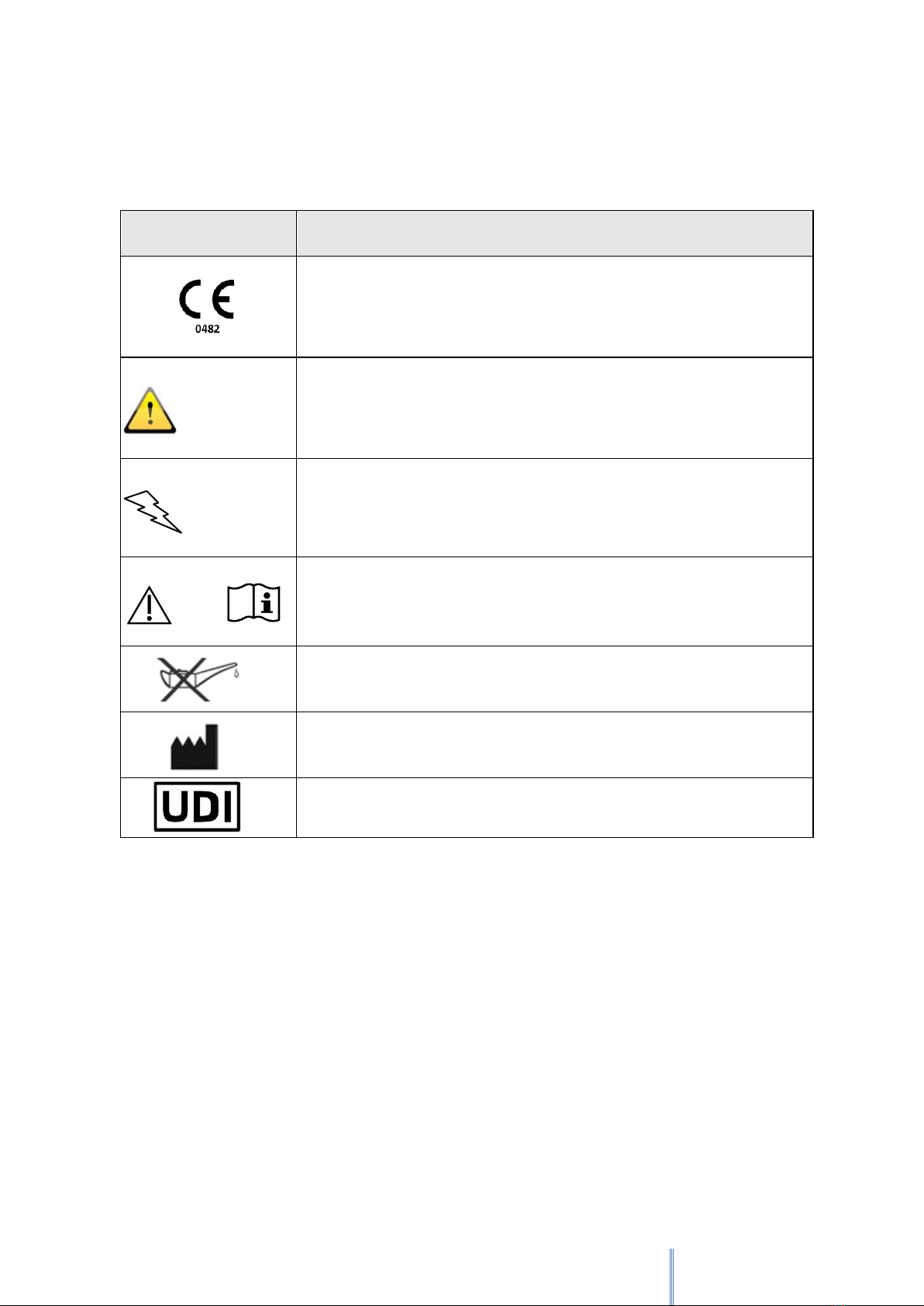
Symbol
Description
This symbol indicates that the device complies with the regulation
93/42/EEC concerning medical devices and all applicable
international standards.
WARNING
Indicates a potentially dangerous situation that, if not prevented,
could result in death or serious injury.
CAUTION
CAUTION is used to indicate a potentially hazardous situation
which, if not prevented, may result in property damage.
or
Refers the user to the necessity of consulting the operating
instructions.
DO NOT USE OIL
Identifies the manufacturer of the medical device according to the
EU directives 90/385 / EEC, 93/42 / EEC and 98/79 / EC
Unique Device Identification
4
4. Before intial usage:
Read all instructions before use!
These operating instructions are intended to show trained professionals how to install and
operate the device. It serves your safety and protects your device from damage. If you do
not understand information or instructions in this document, do not use the device and
contact your supplier.
WARNING
This product is not intended for use as a life-sustaining or life-supporting device.
WARNING
Read through this entire instruction manual before using or showing others how to use
this flowmeter. As with all medical equipment, attempting to use this device without a
thorough understanding of its operation may result in patient or user injury.
Medical gases are, or should be considered a drug and should only be used for
medical purposes as prescribed by a physician or authorized clinician and in
accordance with their instructions.
The flowmeter may only be operated by medical specialists under the direct
supervision of an approved doctor.
The flowmeter is not MRI compatible.
The flowmeter may only be used for the purpose described in these instructions
for use.
The flowmeter may only be serviced by a qualified service technician.
Ensure that the medical gas supply is sufficient for the proposed therapy and is
supplied within the pressure range given in the Device Specification. If the supply
is a gas cylinder, check the cylinder contents gauge regularly.
This flowmeter is only for use with the medical gas indicated on the device label.
Before use, check that the gas cylinder or supply line contains the correct medical
gas. Always check that the flowmeter is connected to the correct gas-specific
terminal unit.
Gas specific connectors are fitted to the flowmeter. Do not attempt to modify the
fittings to suit other gases or fitting systems.
Always observe the EN and DIN standards for medical gas products, flowmeters
and handling of oxygen.
Do not disassemble the flowmeter whilst under pressure.
Secure cylinders to a wall, stand or cart in accordance with local safety regulations.

5
Do not stand in front of a flowmeter or regulator outlet when opening a cylinder
valve.
Do not allow any fluid to enter this device.
The accuracy of the flowmeter can be affected significantly if the input pressure is
other than stated in the technical specification and the device label.
Do not directly connect the flowmeter output to another pressurised gas source as
this may lead to corruption of one or other of the gas supplies (e.g. connecting an
oxygen flowmeter to an air flowmeter via a Y-piece in an attempt to blend their
outputs).
Only use this flowmeter with the flow tube in a vertical position. Failure to do so
may result in incorrect flow rates being displayed.
Make sure that the flow control valve is not clogged or obstructed and that there
is no unwanted pressure. In such cases, there may be temporary changes in the gas
flow.
Arrange the oxygen tubing and gas hose carefully to avoid damage to the hose and
the potential for causing a trip hazard. Never pull or apply excessive force to the
gas hose. A leaking hose may result in high local oxygen and nitrous oxide
concentrations and an increased risk of fire.
Oxygen is not flammable; however the presence of it will drastically increase the rate and
severity of combustion. Oil and/or grease in the presence of an oxygen enriched
atmosphere will become highly combustible. Oxygen must never be allowed to come into
contact with oil, grease or other petroleum-based substances.
Do not use oil or grease on this flowmeter
Do not smoke around oxygen equipment
NOT suitable for sterilization / autoclaving
DO NOT use if there is contamination
DO NOT clean with aromatic hydrocarbons
Caution:
The flowmeter performance may be affected if it is stored or transported at temperatures
outside the range of -20 ° C to +50 ° C.
The performance of the flowmeter may be affected if the flow control valve is over-
tightened when the flow is turned off. Apply the minimum force required to turn off the
gas flow.
6
5. Technical Data:
Model:
Pressure compensated flowmeter for medical gases.
Display according to the float principle.
Material:
Body: Stainless steel, aluminum
Flow tube: Polycarbonat (PC)
Accuracy:
Nominal Pressure: ±10% or 0,5l/min (the higher level counts) of indicated reading.
Temperature: 3% increase or decrease in flow rate for every 5 °C increase or decrease
in temperature
Inlet pressure: 4% increase or decrease per 10 kPa increase or decrease in pressure
compared to the nominal pressure
Inlet Pressure
Range/ Suppy
Pressure Range:
450 kPa ± 50 kPa
Gas Compatibility:
Medical Oxygen and/ or Medical Air (Depending on the model)
Inlet:
G1/4”, DIN, NF, AGA, BS, Uni probe, NIST
Outlet:
9/16“-18 UNF, Hose nippel, external thread G1/4”, G 3/8 “, 9/16 “ UNF
Performance /
Flow scale:
Depending on the model:
0 –3 l/min
0 –6 l/min
0 –15 l/min
0 –32 l/min
0 –85 l/min
Environmental
conditions:
Transport and Storage Temperature: -20°C to +50°C
Operating Temperature: 0 °C to +50 °C
Humidity: 0-95% RH non-condensing
Standards:
ISO 15002 Flow-metering devices for connection to terminal units of medical gas
pipeline systems
ISO 15001 Anaesthetic and respiratory equipment. Compatibility with oxygen
ISO 5359 Low pressure hose assemblies for use with medical gases
EN ISO 14971 Medical devices. Application of risk management to medical devices
EN ISO 15223-1 Medical devices. Symbols to be used with medical device labels,
labelling and information to be supplied. General requirements

7
6. Functional Description:
Scale (depending on the
model)
Precision
Rotating Ball
Flow Tube
Gas Specific
Connector
Flow Control
Valve
Gas Specific Connector
(Blind plug, if not in use)
Outlet

8
7. General Technical Description:
The flowmeter provides accurate control of the flow of oxygen or air for medical purposes in
the range of 0 to 85 l / min (depending on the model). A precision-made rotating ball rises
inside a transparent measuring tube. A scale is printed on the measuring tube, on which the
speed of the gas flow is displayed in liters per minute (l / min). The gas flow through the
measuring tube is regulated by a valve arranged downstream of it.
The flowmeter has been designed for connection for example to an Oxygen –Air Blender.
However, it can also be operated as a "stand alone" device for directly connection to the
medical gas supplies.
Gas Specific Connector
The gas-specific quick connection probe has characteristics to prevent connections between
different gas services.
Connection to the patient
Connect the other end of the oxygen hose system to the patient or the surrounding area with
the appropriate connector.
Setting the gas flow
The flow control valve is turned counterclockwise to turn on and increase the gas flow. If the
flowmeter is not working properly, it should not be used. For troubleshooting instructions, see
section 11 of this brochure.
During use
During therapy or treatment, continuously monitor the gas flow and filling level of the gas
bottle (if applicable) and make sure that the supply and supply hose (if applicable) cannot pose
a risk of tripping.
After use
If the supply is from a gas cylinder, close the cylinder valve and disconnect the flowmeter when
therapy is no longer required.

9
8. Operation Instructions:
WARNING
Safety instructions for avoiding accidents while using an oxygen sampling device:
It is the responsibility of the user to avoid the enrichment of the room or ambient air
with a volume fraction> 21% O2.
Connection to the gas supply
Before use, visually check both the flowmeter and hose (if fitted) for any damage or
contamination. Do not connect or use the device if there are any doubts about its condition.
The flowmeter is supplied with a gas specific connector that is designed to connect to a mating
gas specific outlet. Gas specific outlets might be a terminal unit in a medical gas pipeline
system or part of a pressure regulator outlet on a gas cylinder.
If you are using a cylinder supply, ensure that the cylinder contents are adequate for the
planned therapy and turn on the supply at the cylinder.
Connect the gas specific quick connection to the appropriate gas specific outlet.
Align device to the final vertical position and fully hand tighten the connection before turning
on the supply pressure.
For quick connector probes (e.g. BS 5682, DIN, AFNOR), ensure that the connection is correctly
made by gently pulling the flowmeter body or hose (as applicable) before turning on the
supply pressure.
Setting the gas flow
The flow control valve is turned counterclockwise to turn on and increase the gas flow. If the
flowmeter is not working properly, it should not be used. For troubleshooting instructions, see
section 11 of this brochure.
Reading the Flowmeter
The correct reading level of the set flow is on the marking on the scale for the floating ball (top
of the floating ball).
Connection to the Patient
Connect the other end of the oxygen hose system to the patient or the surrounding area with
the appropriate connector (not supplied).
10
During Use
Continue to monitor the level of gas flow and the contents level of the cylinder (if applicable)
during the procedure or therapy and be aware that the supply tubing and hose (if applicable)
may be a trip hazard.
After Use
If the supply is from a gas cylinder, close the cylinder valve and disconnect the flowmeter when
therapy is no longer required.
9. Cleaning and Disinfection:
Ensure the flowmeter is disconnected from the gas supply before attempting to clean it.
ATTENTION
NOT suitable for sterilization / autoclaving
DO NOT disassemble the flowmeter
NEVER immerse the device in liquids.
DO NOT use strong solvents or abrasives.
DO NOT clean with aromatic hydrocarbons.
The outside of the device must be disinfected at regular intervals or at the latest after each
patient in accordance with the applicable hygiene standards.
If you suspect that the flowmeter is contaminated, take it out of operation and refer the
device to the appropriate department.
Never immerse the flowmeter in any fluid or attempt to clean internal parts.
Cleaning and disinfection steps:
1. Disconnect all gas connections and devices before cleaning.
2. Wipe the outside of the flowmeter and the gas supply hose with a cloth soaked in
alcohol or disinfectant.
3. Wipe the device with a dry cloth.
The manufacturer recommends the use of the disinfectant Dismozon plus®, Bode Chemie
GmbH & Co.

11
10. Maintenance:
Interim Inspection
The flowmeter should be regularly cleaned, inspected for damage and checked for
performance. The frequency of inspection and performance checks depends upon usage. As
a guideline, if the flowmeter is used daily this may need to be performed every six months; if
used infrequently an annual check may be sufficient.
Leak Test
Cponnect the flowmeter to a low pressure medical gas supply with a nominal supply pressure
as specified on the label of the device and close the flow control valve. Connect the supply
hose to the flowmeter outlet and immerse the other end of the hose in water. The presence
of gas bubbles in the water indicates a leak. A flowmeter that fails these tests should no longer
be used.
Flow Test
Verify the flow rates for all flow settings against specification i.e. within ±10% or 0,5 l/min (the
higher value counts) at 1 l/min and above.
Service and Repair
The implementation of the maintenance measures and inspections depends on the type of
use, the conditions of use and the intensity of use. The intervals are to be determined by the
user. However, the flowmeter should be cleaned regularly, checked for signs of damage and
its performance checked. In addition, all silicone seals used in the device must be checked
regularly for perfect condition and correct function and replaced if necessary. A period of 2
years is recommended.
Flowmeters with an indirect connection should have the hose assembly replaced according to
the date specified by the manufacturer. The date of manufacture can be found on the device
label of the hose.

12
11.Troubleshooting:
Failure
Possible Cause
Solution of the Problem
No gas flow
Flowmeter is not
connected properly
Check gas supply; check that the gas-specific probe is
correctly connected
Gas cylinder empty
Replace gas cylinder
Medical gas terminal unit
of a pipeline system is not
connected / active
Seek advice from someone authorised to operate the
isolation valves of the medical gas pipeline system
Inlet filter is blocked
Repair required
Audible gas
leak
Seal is worn or damaged
Repair required
Pressure relief valve leaks
because the inlet pressure
is too high
Check whether the gas supply pressure is within
specification of the device.
Top tube is cracked or
damaged
Repair required
Connection is worn or
damaged
Repair required; Exchange necessary
Medical gas hose damaged
Replacement required
Constant gas
flow
Valve or valve seat
damaged
Repair required
13
12. Articles and Spare parts:
Articles:
Part numbers
Description / Version / Performance
D-B-FL-3
Quality Flowmeter
0 –3 l/min
D-B-FL-6
Quality Flowmeter
0 –6 l/min
D-B-FL-15
Quality Flowmeter
0 –15 l/min
D-B-FL32
Quality Flowmeter
0 –32 l/min
D-B-FL-85
Quality Flowmeter
0 –85 l/min
Spare parts:
Part numbers
Description
D - EM019681
Plug Base Body
D - EM016583
Adapter 9/16“
D - EM017999
O –Ring for base body
D –0232900
Top Tube

14
13. Customer service / Warranty:
a. Warranty conditions
The supplier guarantees that the mixer will be free of material defects or workmanship errors
for the following period:
One (1) year from delivery
If, within the applicable period, a device defect should occur, then the dealer shall –after
written notification thereof and substantiation that the device has been stored, installed,
maintained and operated in accordance with the instructions of the dealer and in accordance
with standard industry practice, and that no modifications, substitutions or changes were
made to the product –correct such a defect by suitable repair or replacement at its own
expense.
ORAL STATEMENTS DO NOT CONSTITUTE A WARRANTY.
The retailer is not authorized to make oral warranties about the merchandise described in this
contract. Any such statements are not binding and not part of the sales contract. Thus, this
written second statement is a final, complete and exclusive statement of the contractual
terms.
The current version of the retailer's Terms and Conditions and German law are valid.
b. Product returns
Please contact your retailer concerning this. They will help to coordinate the return. It is
important that you provide a description of the error or malfunction so that the return can be
processed effectively. All returns must be shipped in sealed containers to prevent damage.
The specialist retailer is not responsible for any devices that are damaged during transport.
c. Disposal
This device and its packaging contain no hazardous materials. No special precautions are
required when disposing of the device and its packaging.
Please disinfect and recycle!

15
10. Manufacturer Information:
Manufacturer:
DEHAS Medizintechnik & Projektierungs GmbH
Wesloer Straße 112
23568 Lübeck
Germany
Phone: +49 451 80 90 4 - 112
Fax: +49 451 80 90 4 - 111
Email: [email protected]
Homepage: www.dehas.de
Distribution
DEHAS Medizintechnik & Projektierungs GmbH
Wesloer Straße 112
23568 Lübeck
Germany
Phone: +49 451 80 90 4 - 112
Fax: +49 451 80 90 4 - 111
Email: [email protected]
Homepage: www.dehas.de
Rev. 1.1 Version 08.05.2020
This manual suits for next models
4
Table of contents
Other DEHAS Measuring Instrument manuals

Popular Measuring Instrument manuals by other brands

Conrad Electronic
Conrad Electronic 100515 operating instructions

Alpes Lasers
Alpes Lasers Cascade Laser Starter Kit instruction manual

AFRISO
AFRISO Unitel operating instructions

Cincinnati
Cincinnati CL-900 Series Operation, safety and maintenance manual

C-LOGIC
C-LOGIC 8730 instruction manual

Kessel
Kessel SonicControl Installation, operation and maintenance instructions


