wh085ba04a(P14-5)
NOTE
Design and specifications are subject to change without notice.
Specifications
3-3
●Speedometer Display range : 0 ~ 160 km/h (MPH)
Display unit : 20 km/h (MPH) (Large grid),
10km/h (MPH) (Small grid)
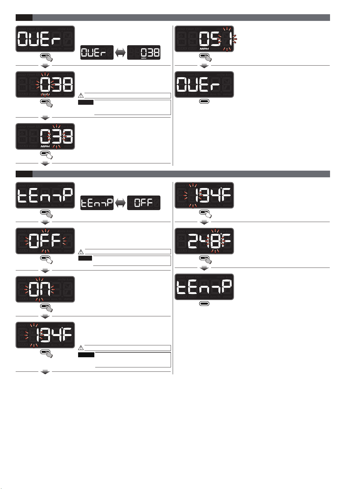
Display range : 30~160 km/h (19~100 MPH),
when setting value is reached or above, warning
light will iluminate.
Display unit : 1 km/h (MPH)
○Low voltage warning
●
Voltmeter Display range : DC 8.0 ~ 18.0 V
Display unit : DC 0.1 V
●Clock Setting range : 00:00~23:59 (24H)
01:00~12:59 (12H)
●Operating temperature -10~ +60 °C
○Storage temperature -20~ +80 °C
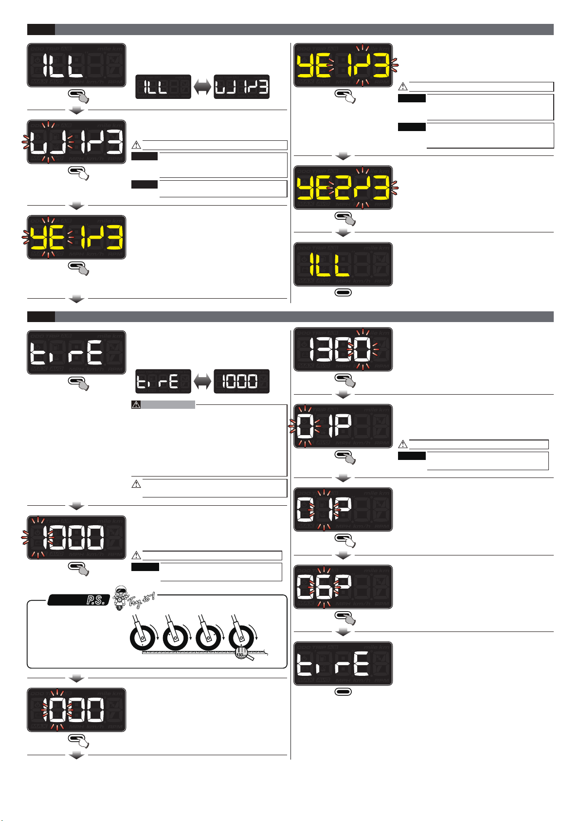
●
Backlight brightness
○Backlight color Setting range : white, red, orange, yellow, green,
blue, light blue, purple Loop switch
High beam light (Blue)
Turn signal light (Green)
Composite warning light (Red)
Speeding warning (Red)
Motor oil light (Red)
Neutral light (Green)
Check engine light (Amber)
○Operating voltage DC 12V
●
Specification JIS D 0203(S2)
●
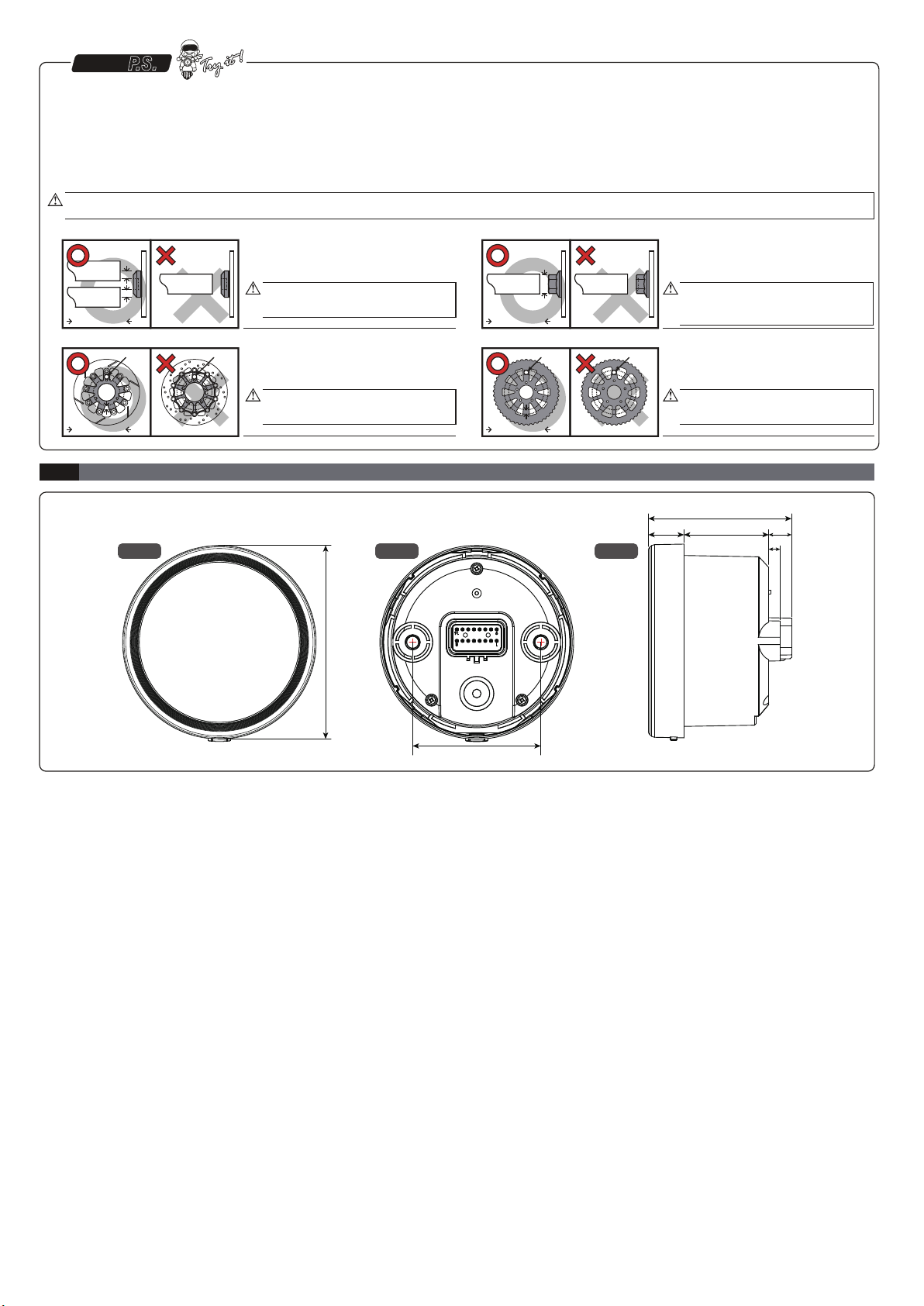
Meter Size D 60 mm
●
Meter Weight ± 100 g
●Indicator
●
Unit Speed unit : km/h , MPH
Temperature unit : ˚C (Celsius) and ˚F (Fahrenheit)
●
Composite warning light
○
Max. speed record
○Odometer
○Trip meter A, B
Display range : 0~160 km/h (MPH),
can return to zero manually
Display unit : 1 km/h (MPH)
Setting range : 0 ~ 99,999 km (mile)
Setting unit : 1 km (mile)
Display range : 0.0~9,999.9 km (mile),
can return to zero manually
Display unit : 0.1 km (mile)
○Circumference
Setting range : 300~2,500 mm
Setting unit : 1 mm
○Sensitive point
Setting range : 1~20 P
Setting unit : 1 P
●
Temperature Display range : 0.0~250.0 °C (32.0~482.0 °F)
Display unit : 0.1 °C (°F)
Setting range : 60~250 °C(140~482 °F),
when setting value is reached or above, warning
light will iluminate.
Setting unit : 1 °C (°F)
●Fuel meter
油量表阻抗值 Setting range : 100 Ω, 250 Ω, 270 Ω, 390 Ω,
510 Ω,1200 Ω, Sw, Custom(learning mode), OFF
○Low Fuel warning Setting range : 0~30%, when setting value is
reached or below, warning light will illuminate.
Setting unit : 10%
Display range : 0.0~250.0 °C (32.0~482.0 °F)
, can return to zero manually
Display unit : 0.1 °C (°F)
Display range : 10 levels (100%)
Display unit : 1 levels (10%)
Setting range : DC 8.0~13.0 V, when setting value
is reached or below, warning light will illuminate.
Setting unit : 0.1 V
Setting range : Low Fuel(LFUEL), Low voltage(VOLT),
Overheat(TEMP).
Setting range : Lit.(L), Slow Flash(S), Fast Flash(F),
OFF
Setting range : 1/3(Darkest)~ 3/3(Brightest)
Setting unit : 1/3
3-2
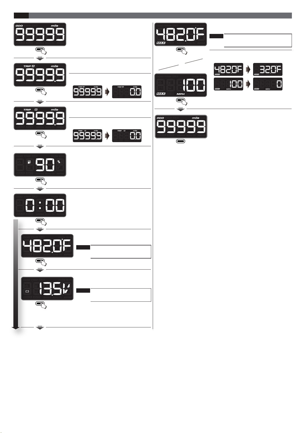
Basic Function Instructions
Odometer
●Display range : 0 ~ 99,999 km (mile)
●Display unit : 1 km (mile)
Trip meter A, B
●Display range : 0.0~9,999.9 km (mile)
●Display unit : 0.1 km (mile)
Fuel meter
●Display range : 10 levels (100%)
●Display unit : 1 level (10 %)
Clock
●Setting range : 00:00~23:59 (24H)
01:00~12:59 (12H)
Thermometer
●Display range : 0.0~250.0 °C (32.0~482.0 °F)
●Display unit : 0.1 °C (°F)
Voltmeter
●Display range : DC 8.0 ~ 18.0 V
●Display unit : DC 0.1 V
Speedometer
●Display range : 0 ~ 160 km/h (MPH)
●Display unit : 20 km/h (MPH) (Large grid),
10km/h (MPH) (Small grid)
Button
Max. speed record
●Display range : 0~160 km/h (MPH)
●Display unit : 1 km/h (MPH)
Max. temperature record
●Display range : 0.0~250.0 °C (32.0~482.0 °F)
●Display unit : 0.1 °C (°F)
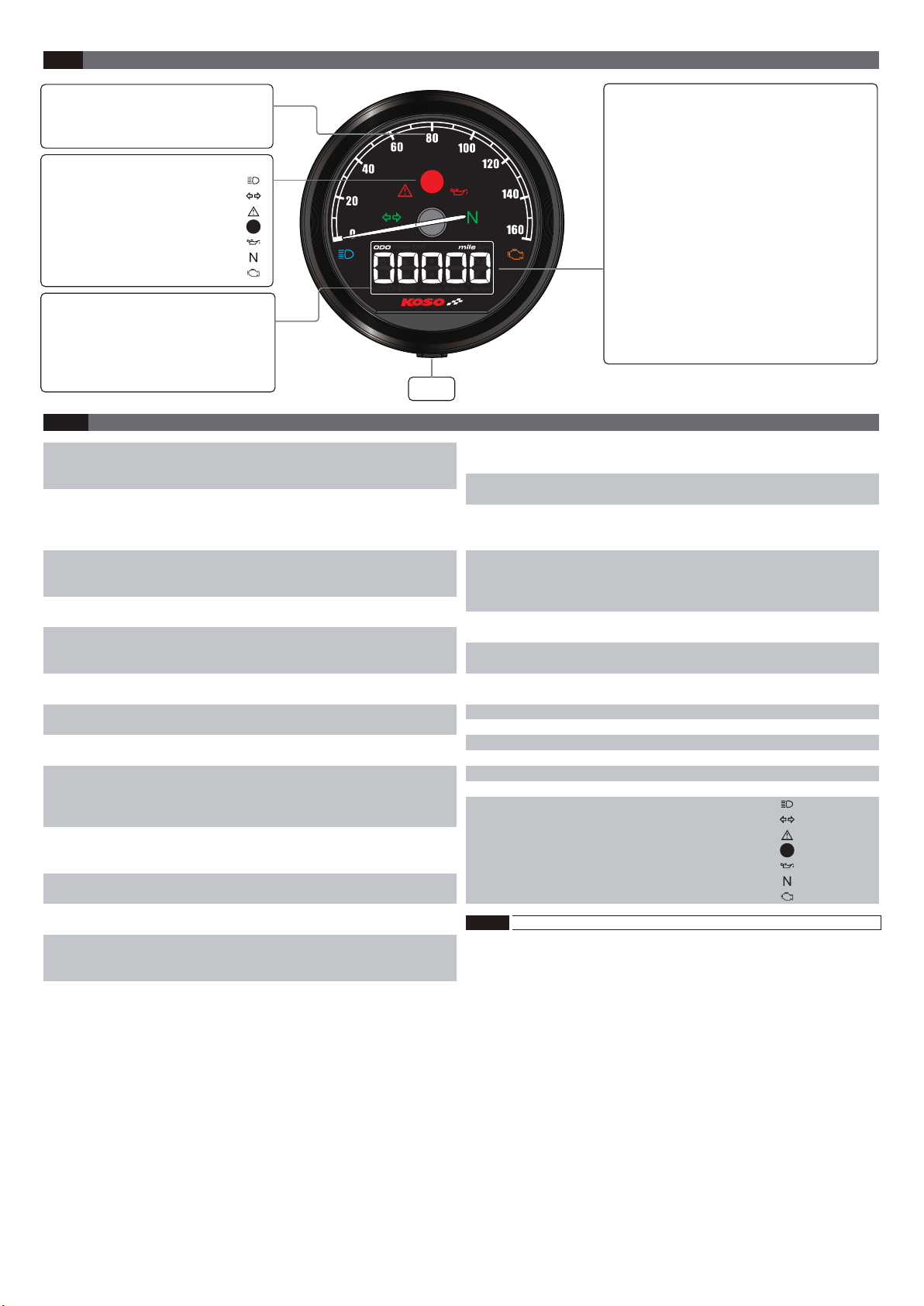
Indicator
●High beam light (Blue)
●Turn signal light (Green)
●Composite warning light (Red)
●Speeding warning (Red)
●Motor oil maintenance light (Red)
●Neutral light (Green)
●Check engine light (Amber)
○
Speeding warning
setting
○
Overheat warning
○Max. temperature
record
○Fuel Gauge
Resistance(Ω)