Hogtunes NCA 450-RM User manual

HOGTUNES
Audio Solutions For The Great American Cruiser
Designed and Engineered in Canada For
The Great American Cruiser
Limited-RM
Installation Manual
For Use On 2014+ (Non-CVO)
Liquid Cooled FLH Touring Bikes
Version 1.0
www.hogtunes.com
Any audio system can be a distraction to the rider
and/or passenger. Please use caution when
playing your stereo, especially in trac.

Thank-you for choosing the Hogtunes Limited-RM Kit. Since positive word of mouth
is the best way to grow our business, we want your new system to work as well as it
was designed to. If you have any questions or concerns, we are here to help. Email
If you still need help, please consider a professional installation by your dealer.
Getting Started:
Step #1: Remove the seat, and both wires (+ and -) from the battery.
Step #2: Remove the outer fairing/headlamp assembly. Refer to a service manual if
you need help with this. Note: A towel on the front fender can help prevent
scratches or “dings” from dropped tools or fasteners etc. Colorful expletives and
ying wrenches will most likely also be kept to a minimum.
Rear Speakers:
Step #1: Remove the factory rear speaker grills by undoing the 4 screws on the front
of the grills. Carefully lift up on each speaker and take the 2 wires o by pulling one
at a time from the stock speaker. Remove the speakers.
Step #2: Locate the Hogtunes 362R-RM (rear speakers) that came in the kit. The
female OE connectors mate with the male connectors on each speaker and only go
on one way. Once you are condent the factory wires are correctly attached to the
new speakers, set them in place, install the grills that came with the kit and secure
the speaker by reinstalling the 4 screws per grill. It’s a good idea to get all 4 grill
screws “started” and then get each one snug. Gradually tighten each one down
making sure all 4 screws holding the grill down are snug but secure!
Front Speakers:
Step #1: On the brake side speaker cabinet, carefully remove the cable going into the
power port/cigarette lighter assembly. If your bike has the CB module (mounted
“sideways” on the clutch side cabinet) undo the antenna cable and main harness.
The CB Module will stay attached to the clutch side cabinet when removed. Undo the
speaker wire plugs going into each cabinet (pink & pink with black stripe wires).
Smaller harnesses are attached to the cabinets with “Christmas tree” fasteners, and
are easy to pull o. Figure 1.1 and 1.2 (on next page) have arrows that point to the
factory fasteners that will be removed to allow the cabinets to come out of the bike.
Although the brake side is shown on next page, fastener locations are common for
both brake and clutch side cabinets.
This Kit Has The Amplier Power the Front And Lower Speakers While The
Radios Built In Amplier Powers the Rear Speakers.
This System is Designed To Work With Factory Radio Software.
NO DEALER RADIO SOFTWARE “REFLASHES” ARE REQUIRED!
2
NOTE: We STRONGLY suggest completing the front speaker installation
on one side of the bike and then moving to other side!
Harley-Davidson, Electra Glide, Road Glide, Street Glide, Ultra Classic, Tri Glide
CVO, Screamin Eagle and Tour-Pak® are Trademarks, and/or Registered
Trademarks of Harley-Davidson, Inc., Milwaukee, Wisconsin, USA, and if
Used or Implied are for Reference Only. There is No Aliation
Between Harley-Davidson, Inc., and Hogtunes Inc.
11

Step #2: With the cabinet removed from bike undo the 4 screws that hold the
factory speaker to the cabinet. Carefully take o each speaker wire by
disconnecting one at a time. Take a Hogtunes 362F-RM (front) speaker and
attach the factory speaker wires noting they will only go on one way ,and that
the built in barbs will secure the factory connectors. Using the factory screws,
attach the Hogtunes speaker to the cabinet noting that there is a locator
“peg” on the cabinet and a hole in the speaker’s frame which need to line up.
The factory speaker grill can be left in or replaced with the supplied metal
mesh grill using the 3 factory screws on the inside of the fairing. On the
Hogtunes grill, you will see two holes and one “keyhole” where the screws go
through and into the fairing. The keyhole in the Hogtunes grill needs to be
oriented so it is closest to the radio on each side for proper tment. Please
note that the Hogtunes mesh grills will allow the speakers to play louder than
the factory cloth covered grills! With the grills in place and the speaker
properly attached to the speaker cabinet, the cabinet can be re-installed.
Repeat Step #2 for the second cabinet. Don’t re-attach the speaker connectors
on the cabinets back to the bike yet. Make sure to plug the power cable back
into the power port/cigarette lighter assembly on the brake side as well as
reattaching the wire harnesses to the cabinets with the factory “Christmas
Tree” fasteners. If your bike has the CB module, make sure to re-install the
antenna cable and main harness.
3
Figure 1.1 Side View of
Brake side cabinet
Figure 1.2 Back View of
Brake side cabinet
Technical Specications:
362F-RM Front and 362R-RM Rear Speakers
Power Handling: 125 RMS-200 Peak
Frequency Response: 55hz-25Khz
Sensitivity: 92 db 1watt/1meter
Nom. Impedance : 2 Ohms
NCA 450-RM Amplier
Amp’s RMS Power at 2Ω: 50 Watts x 4 Channels
Frequency Response: 40hz - 25khz
Fuse at Amp: 30 amp
Topology: Class A/B
10

Installing the Amplier:
Step #1: Over top of the radio, pull up to release each wire harness from the black
plate via the factory “Christmas Tree” fasteners. If your bike has factory GPS, the
small square antenna will need to be relocated just behind the voltmeter as shown
in Fig 1.1 below. Remove the 4 factory “Torx” screws that go through the top of the
black plate and into the top of the radio. Set these screws aside for now.
Step #3: The amplier comes shipped pre-mounted to a silver mounting plate.
Locate and remove the 4 screws (2 per side) that attach the amp to the silver plate.
Put these screws just removed and the amplier aside for now.
Sit the supplied silver plate (without amp) on top of the radio so its oriented as
shown below. Locate and install one of the supplied “star” washers on each factory
screw, and reinstall the screw & washer through the silver plate, through the
factory black plate and into the top of the radio.
Fig 1.1: The white circle
shows the new location
for GPS Antenna if your
bike came equipped with
this feature.
Fig 1.2: Amplier and mounting
plate correctly oriented. The
plate with 4 small holes is for
mounting a popular factory
accessory. The white circle
show tabs which are there for
the factory “Christmas Tree”
fasteners to re-secure the
harnesses lifted earlier. A
4
Warranty Information:
Please Record Your Amps Serial # Here_________________________
Hogtunes speakers are warranted for a period of 20 years. The NCA 450-RM
Amplier is warranted for 3 years from original purchase date. Proof of
purchase is required for all warranty claims. The warranty applies to the
original retail customer, and is not transferable. Please contact Hogtunes
for all warranty claims. Products found to be defective during the warranty
period will be repaired or replaced (with a product deemed to be
equivalent) at Hogtunes sole discretion. Hogtunes complete warranty
policy is available on our website at www.hogtunes.com/warranty.html
What Is Not Covered:
1) Any expense related to the removal or re-installation of Hogtunes products.
2) Repairs to these products performed by anyone other than Hogtunes.
3) Subsequent damage to any other components.
4) Any product purchased from a non-authorized Hogtunes dealer.
5) Damage to Hogtunes products due to an accident or collision.
6) Paint applied to any part, for any reason
7) Speaker frames (baskets) that are bent or broken
8) Speaker cones that are pierced or cut
9) Damage caused by overtightening, or not using supplied fasteners
10) Damage from use of “Thread Lock or Screw Glue” materials of any kind
11) Damage to inbound product due to improper packing.
IMPORTANT: In the event of a warranty claim, please fill out the form in the
Warranty section of our website, or contact us by email, or by phone. Valid
claims will have an Return Authorization Number (RA#) generated which
MUST appear on the outside of the box when it arrives to our offices.
Goods Arriving Without an RA# will be refused!
9

Step #4: On the side of the amp, you will see a “Fader/No Fader” Switch. For this
system, make sure the switch is in the “No Fader” Position. When the installation is
complete, if you adjust the radios fader, the fairing and lower speakers will be on the
“front half” of the fader and the rears will be on the “rear half”.
Step #5: Locate the main power harness and plug it into the matching “pig-tail” on
the side of the amp. Locate the harness with blue/black and brown/black wires, and
insert the 4 pin plug into the “front out” socket on the side of the amp. Locate the
“LC Lower” wire harness and insert the matching plug into the “rear out” on the
amp. Locate the harness with the green/black and yellow/black wires and install the
rectangular 8 pin socket into “audio in” on the side of the amp.
Step #6: Sit the amp on top of the silver plate so when standing in front of the bike
you can read the Hogtunes logo on top of the amp. Re-install the amp to the plate
using the four screws removed earlier.
Step #7: Fig 1.2 (on previous page) has a white square which shows a smaller white 2
pin factory plug behind the bikes voltmeter. Locate the amps orange wire on the
power harness and plug it directly into this factory harness. This is the ampliers
“turn on” lead and tells the amp to turn on/o with the bikes ignition. If you have a
factory accessory already plugged into the factory connector, you will need to splice
the amps orange wire in. This wire draws less than 0.5A when activated.
Step #8: The plug with the blue/black wires will install into the factory plug that
goes directly into the brake side speaker cabinet. The plug with green/black wires
will install into the factory connector that originally plugged directly into the brake
side speaker cabinet. The plug with the brown/black wires will install into the factory
plug that goes directly into the clutch side speaker cabinet. The plug with yellow/
black wires will install into the factory connector that originally plugged directly into
the clutch side speaker cabinet
Step #9: The power/ground harness will pass together under the inner fairing where
the main wire harness passes through on the brake side of the bike. Loosen the tanks
“chrome console” and run wires up and over the gas tank, but under the tanks
chrome console. There is a provision on the front of the tank console for wires to
pass. Note: Although not necessary, the power and rear harnesses can go under the
gas tank if you choose to remove and reinstall the tank. When correctly installed, the
power and ground wires are the right length to connect to the battery, but please do
not connect them yet.
Stock Harness and Ampliers Harnesses
Passing From Fairing To Just In Front Of
Tank (Arrow A) . Cable Tying the Harnesses
To The Main Bike Harness Just In Front Of
The Tank (Arrow B) Allows The Amp
Harnesses To Go Up Towards The Tanks
Chrome Console Easier And Makes For a
Cleaner Install.
B
5
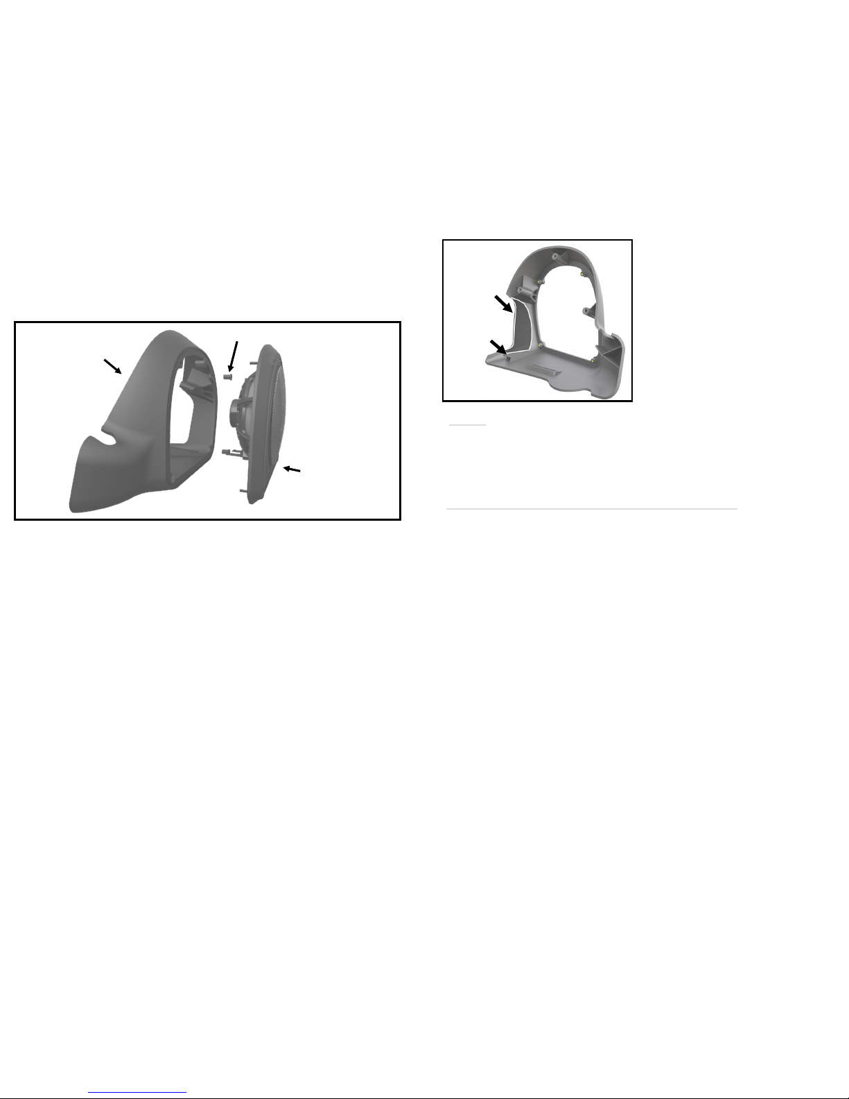
Take the Hogtunes panel with the speaker and plug the speaker wires into the speaker
noting they will only go on one way, and that barbs built into the speaker will lock the
connectors in place. The rubber compression nuts are now placed into the openings on
the front of the main panel and using the screws removed earlier, the speaker panel is
attached to the main lower panel. The threads on the compression nuts are brass so
please make sure the screws are snug but don’t overtighten.
Repeat the steps to install the lower adaptor for the other side of the bike.
With the lowers complete, use the supplied zip ties to secure the lower wires to the
crash bar.
At this point, all audio connections for this system are made. Attach the amps red wire
to the positive (+) battery terminal, and the amps black wire to the negative (-) battery
terminal. The factory battery wires are also re-installed at this point. When attaching
the power and ground wires, it is always a good practice to do the positive rst. When
the nal connector touches the battery, some sparking is normal. This is a function of
the capacitors in the amplier charging up. Turn the stereo on, and at low volume,
test to make sure all 6 speakers are working. Make sure the radios fader control
is adjusting the volume between the front 4, and 2 rear speakers. If not, make
sure the “fader/no fader” switch is in the “no fader” position.
Re-install the seat.
This is the best time to take a few minutes to “clean up” any amplier wiring
using the supplied zip-ties.
Before re-installing outer fairing, turn front wheel to
each extreme side making sure any wiring is not
impeding the steering of the motorcycle.
Failure to do so can result in serious injury or death!
Re install the bikes fairing and your new system is ready to enjoy!
8
A

Lower Speakers:
Step #1: On the speaker panel, you will see 4 black screws that need to be
removed. These screws go into rubber compression nuts that hold the speakers
panel to the main lower panel. These compression nuts will also come o and be
put aside with the screws.
Step #2: Starting on the brake side lower fairing, use a coin or something similar to
carefully pry o the front access cover. Look inside the lower opening and at the
very back, you will see a 7/16” nut that is to be removed. This nut allows the
painted fairing lower “cap” on the front to come o. With the painted cap o, you
will see a bar that secures the top half of the lower to the crash bar. Remove the 2
nuts and the bar and put aside for now. At the bottom of the lower is a clamp that
holds the bottom half of the lower to the crash bar. Remove the bolt that secures
the clamp.
Step #3: Gently push the top of the lower towards the back of the bike just enough
so you can remove the 3 torx screws (normally hidden by the painted cap) that
hold the lowers factory front panel in place. Gently pull on the front panel to
release 2 clips which will allow the front panel to come away, but not completely
free from the bike yet. There is a small arm for the vent mechanism still attached
that is removed by squeezing the top of the pivot pin and lifting up on the arm.
You can now bring the factory lower front panel to a work bench and remove the
torx screw that holds the vent adjuster and arm to the factory panel. Using the
same screw, install the vent adjuster and arm into the Hogtunes main lower panel.
Speakers Panel
Main Lower Panel
Compression Nut
6
Step #4: The kit comes with die cut foam
panels. Find the one for the side of the
bike you are working on and apply as
shown noting you should clean the area
with isopropyl alcohol rst.
Step #5: On the back of your factory front
panel, you will see 2 white clips. One of
these clips will come o and be installed
onto the Hogtunes part as shown.
Step #6: Moving to the front side of the lower, in the area normally hidden by the
painted cap, you will see a hole where the bolt passes through that secures the
painted cap. Just above that hole and approximately 2” back from the bolt hole on
the “top” of the lower, you will need to drill a 3/8” hole for the wires to pass. When
this install is nished, the painted cap will hide the wire nicely. It’s a good idea to
start with a pilot hole and then drill the nal size. Please use caution to make sure
your drill bit does not pierce the coolant tank on the brake side!
Step #7: On the lower harness (plugged into the “rear out” on the amp) you will
see the main harness (4 wires), and two 2 wire harnesses that need to be
unplugged from the main (4 wire) harness. We have you separate these to help
eliminate the extra plugs possibly scratching your bike while routing. The balance
of the main wire harness will pass through where the power harness passed so it
ends up on top of the crash bar as close to the center as you can (see image on bot-
tom of page 5 for reference). Locate the 2 wire harness (just removed) marked
brake side and plug it into the connector now on the crash bar. The other side of
the brake side harness will go into the lower through the hole just drilled. Its easier
to pass the larger of the 2 connectors rst. Once the wires are in the lower, take
up the slack along the crash bar keeping the main harness as close to the center of
the crash bar as possible. The kit comes with strips of black gummy material. Take
one of the strips and use it to seal the hole around the wire on the outside of the
lower. With the wires secured and properly in place, reinstall the painted fairing
cap.
Step #8: Take the Hogtunes front panel and while holding it close the lower, snap
the arm for the vent back into place on the pivot pin rst and then press the front
panel onto the lower noting the one clip will snap in and hold the panel in place.
Re install the 3 factory torx head screws (by hand just until they are snug) to secure
the panel to the lower. The “bar” and 2 nuts removed earlier that secure the top of
the lower to the crash bar will now be reinstalled. The bolt removed earlier that
secures the lower to the bottom of the crash bar is also re installed.
7
Foam Panel
Goes Here
Factory
White Clip
Goes Here
Other manuals for NCA 450-RM
1
This manual suits for next models
2
Table of contents
Other Hogtunes Speakers System manuals