C/ Dolors Bassa, 3 P.I. Cal Batlle - 17400 Breda (Girona) | www.encoderhohner.com | info@encoderhohner.com | +34 972 160 017
8
7
6
1
4
2
5
SW2,5
8
76
22 mm
SW2,5
22 mm
Shield
GND
+UB
A+
B+
A-
B-
Z+
Z-
Z-
Z+
B-
A-
B+
A+
+UB
GND
Shield
3
95.0008074
200mm
95.0004230
M5
95.0000636
M5
95.0004148
M5x16
1312 15
x2 x2
14
x2
It is recommended to mount the device with cable connecon facing down-ward.
Se recomienda montar el disposivo con el cable orientado hacia abajo.
Color Signal
WH GND
BN VCC
RD A+
BK B+
BU A-
VT B-
GY 0+
PK 0-
2m Cable
5x2x0,14+2x0,34
double-shielded
Pin Signal
1 GND
2VCC
3 A+
4 B+
5A-
6 B-
7 0+
8 0-
9 -
10 -
11 -
12 -
M23 Connector
Conector M23
12p CW
Pin Signal
1 GND
2VCC
3 A+
4 B+
5A-
6 B-
7 0+
8 0-
M12 Connector
Conector M12
8p CCW
General Notes (EN)
• Observe the applicable law, direcves and standards for
use respecvely intended use.
• Installaon, electrical commissioning or any other
maintenance operaons at encoder is to be performed
by appropriately qualied sta only.
• The expected operang life of the device depends on
the ball bearings, which are equipped with a permanent
lubricaon.
• The storage temperature range of the encoder is
between -15°C and +70°C.
• The operang temperature range of the encoder is
between -20°C and +80°C (-40..+80°C with Special
Customer YT00, or -20..+100°C with Special Customer
YT01), measured at the housing.
• EU Declaraon of Conformity meeng to the European
Direcves.
• Maintenance work is not necessary. The device may only
be opened as described in this instrucon. Alteraons of
the device are not permied.
• Damaging the seal on the device invalidates warranty.
• Do not dispose of electrical and electronic equipment
in household waste. The product contains valuable raw
materials for recycling.
Electrical Safety
• Turn OFF power supply before connecng the encoder
and ensure machinery is staonary.
• Make sure the enre system installaon is EMC compliant.
• Electronic parts are sensive to high voltages:
- Do not touch plug contatcs or electronic components.
- Protect output terminals against external voltages.
- Do not exceed max. operang voltage.
• Dirt penetrang inside the encoder can cause short
circuits and damage the sensing system.
Mechanical Safety
• Install the encoder following strictly the installaon
instrucons informaon.
• Hair and clothes may become tangled in rotang shas.
• Never restrict the freedom of movement of the encoder.
It is essenal that the specied clearances and /or angles
are observed.
• Delicate equipment; handle with care and not subject the
device to force, knocks or shocks.
• All indicated ghtening torques are recommended.
Indicaciones Generales (ES)
• Siga las leyes, direcvas y normas estándar aplicables a
su respecvo uso.
• La instalación, la puesta en marcha eléctrica o cualquiera
otra operación de mantenimiento del encoder debe
ser realizada únicamente por personal debidamente
cualicado.
• La vida úl prevista del disposivo depende de los
rodamientos de bolas, que están equipados con una
lubricación permanente.
• Rango de temperatura de almacenamiento entre -15°C
y +70°C.
• Rango de temperatura de funcionamiento entre -20°C
y +80°C (-40..+80°C con Ejecución Especial YT00, o
-20..+100°C con Ejecución Especial YT01), medido en la
carcasa.
• Declaración de conformidad de la UE con las direcvas
europeas.
• El trabajo de mantenimiento no es necesario. El
disposivo solo se puede abrir como se describe en
estas instrucciones. No se permiten alteraciones del
disposivo.
• Dañar el sello del disposivo invalida la garana.
• No deseche los equipos eléctricos y electrónicos en la
basura domésca. El producto conene materias primas
valiosas para reciclar.
Seguridad Eléctrica
• Apague la fuente de alimentación antes de conectar el
encoder, y asegúrese de que la maquinaria esté parada.
• Asegúrese de que toda la instalación del sistema sea
compable con EMC.
• Las partes electrónicas son sensibles a altos voltajes:
- No tocar los enchufes ni los componentes
electrónicos.
- Proteger los terminales de salida de tensiones
externas.
- No sobrepasar el máximo voltaje.
• La suciedad en el interior del encoder puede provocar
cortocircuitos y dañar el sistema de detección.
Seguridad Mecánica
• Instalar el encoder respetando estrictamente las
instrucciones de instalación.
• El cabello y la ropa pueden enredarse en ejes rotavos.
• No restringir el movimiento del encoder. Se deben
respetar las distancias y ángulos especicados.
• Equipo delicado; manéjelo con cuidado y no someta el
disposivo a fuerza, golpes y choques.
• Todos los pares de apriete indicados son recomendados.
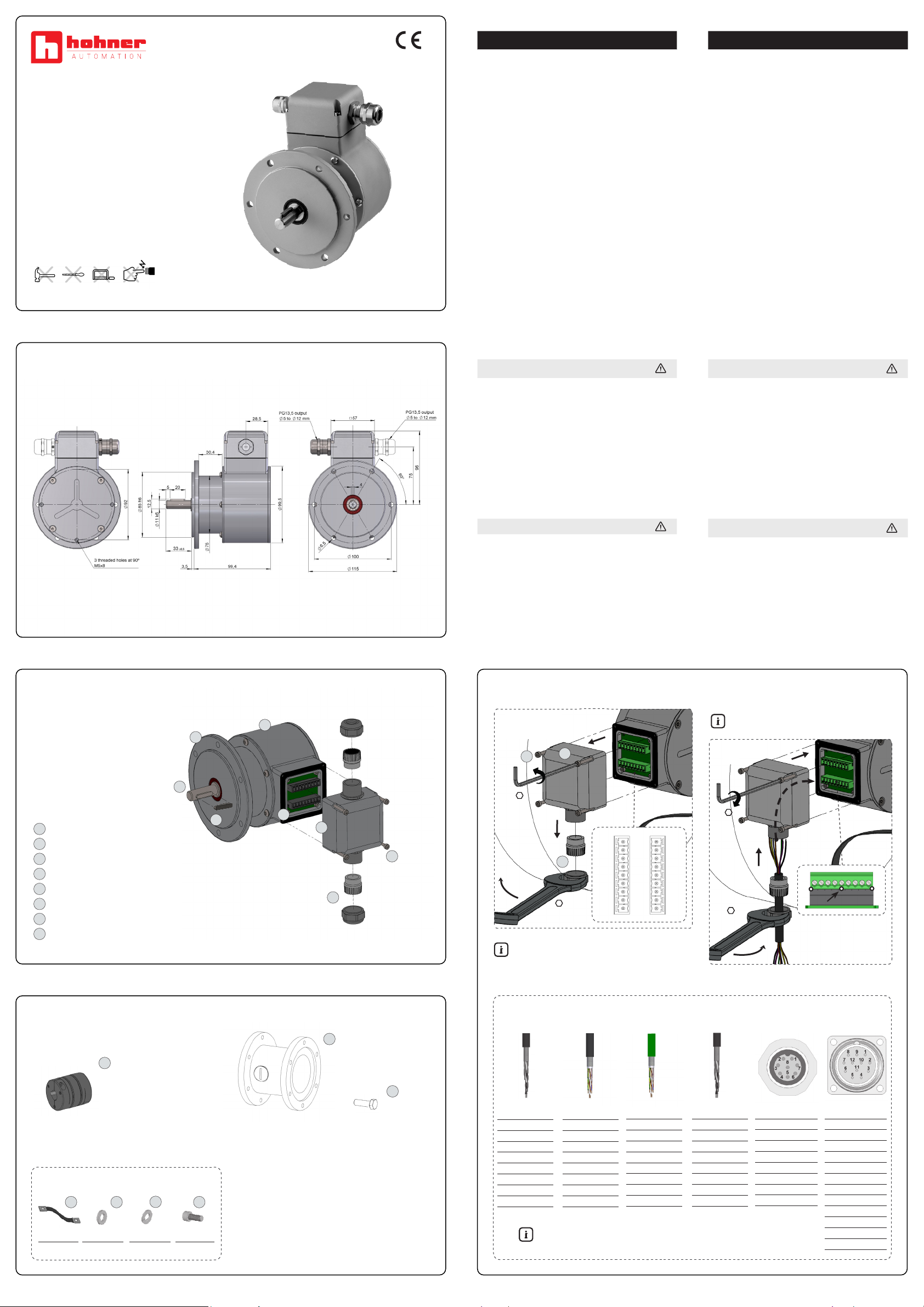
100
100 DUO
Mounting Instructions
Instrucciones de Montaje
Included in delivery / Incluido en el suministro
1Housing / Cuerpo
2Solid shaft / Eje saliente
3Shaft key / Chaveta
4EURO flange B10 / Brida Euro B10
5Connection board / Placa de conexiones
6Terminal box cover / Tapa de caja de bornes
7Screw M3x25 (x4) / Tornillo M3x25 (x4)
8Cable gland PG13,5 for cable Ø5..12mm /
Prensa estopa PG13,5 para cable Ø5..12mm
Not included in delivery / No includio en el suministro
10
Installation fitting
Customized
Campana de instalación
Personalizada
DOC.ENCI.100.M.EN-ES.001 04/21
Dimensions / Dimensiones
11
Screw M6x16
For installation fitting
Tornillo M6x16
Para campana de
instalación
9
Spring disk coupling. Available as accessory
Acoplamiento de disco. Disponible como accesorio
LFA 3437 - LFA 4447 - LFA 3832 - LFA 3850
A shielded twisted pair-cable must be used.
Usar un cable apantallado trenzado en par.
Terminal box
Caja de bornes
Electrical connection / Conexión eléctrica
It is recommended to use a threadlocker.
Se recomienda usar un jador de roscas.
* It is recommended to add silicone
dots between connectors.
Se recomienda añadir puntos de
silicona entre conectores.
Tightening torque /
Par de apriete:
Mt= 0,7-0,8 Nm
Earthing strap / Malla de tierra
00.0003006
Color Signal
BK GND
RD VCC
YE A+
GN B+
BN A-
BU B-
GY 0+
OG 0-
2m Cable
3x2x0,14+2x0,34
standard
Color Signal
WH GND
BN VCC
GN A+
BU B+
YE A-
RD B-
GY-PK 0+
RD-BU 0-
2m Cable
5x2x0,14+2x0,34
up to 100°
Color Signal
WH GND
BN VCC
RD A+
BK B+
BU A-
VT B-
GY 0+
PK 0-
2m Cable
5x2x0,14+2x0,34
double-shielded
halogen-free


