Hokuetsu AIRMAN PDS185S-6EZ1 User manual


Preface / Table of Contents
Thank you for having selected our “AIRMAN” product.
Keep this manual at hand to refer to it always when necessary.
When this manual is missing or damaged, order it from our office nearby or distributor. Make sure
that the manual is included with the machine when it is handed over to another user.
The contents of this manual may differ from the machine because of design changes. If anything is
unclear, please contact our office or your nearest dealer for clarification.
For details of handling, maintenance and safety of the engine, see the Engine Operation Manual.
―Table of Contents ―
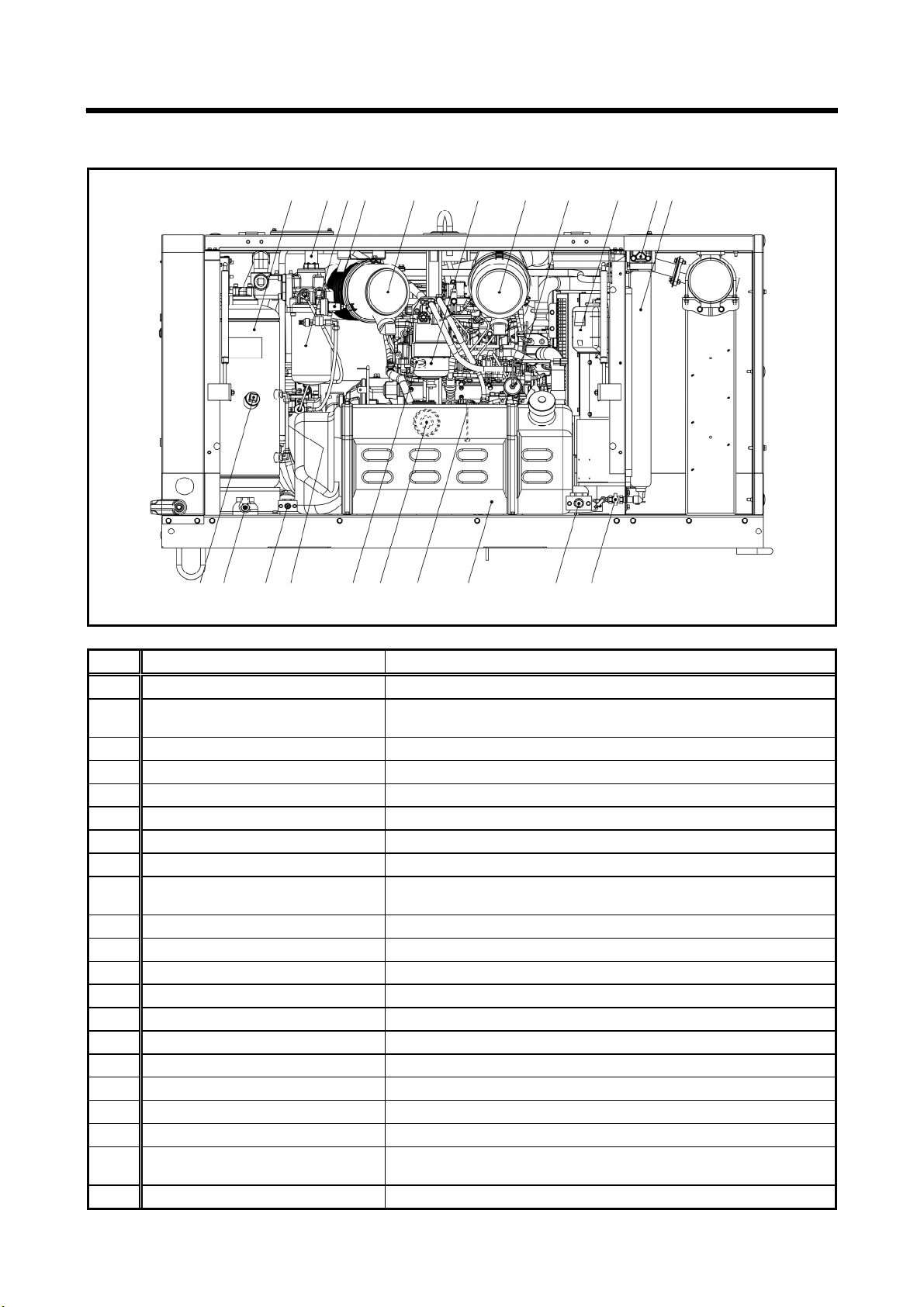
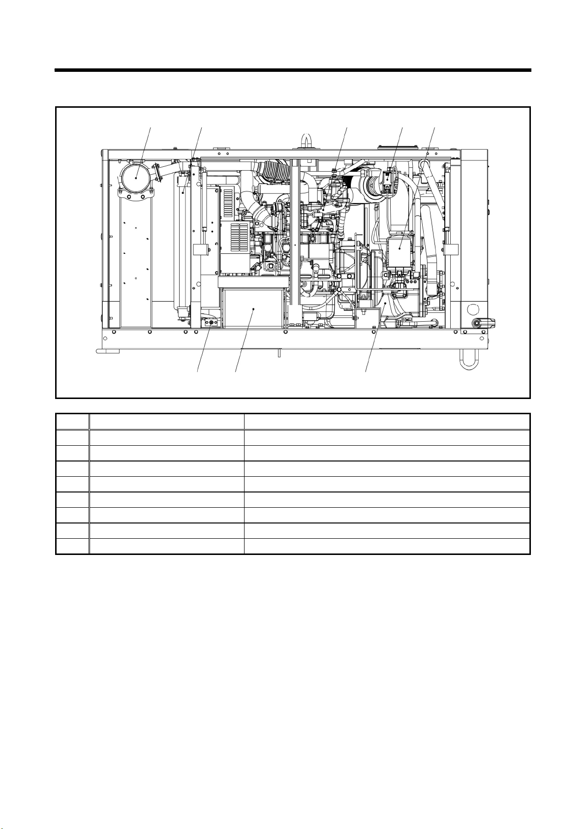
1. Part Names --------------------------------------------------------------------------------------- 1-1
1.1 Internal Components and Part Names ---------------------------------------------------------------------- 1-1
2. Installation ---------------------------------------------------------------------------------------- 2-1
2.1 Transportation ---------------------------------------------------------------------------------------------------- 2-1
2.2 Towing the Machine --------------------------------------------------------------------------------------------- 2-2
2.3 Installation conditions ------------------------------------------------------------------------------------------- 2-3
3. Operation ----------------------------------------------------------------------------------------- 3-1
3.1 Instrument Panel ------------------------------------------------------------------------------------------------- 3-1
3.2 Lubricating oil・Coolant・Fuel ------------------------------------------------------------------------------- 3-2
3.3 Check before starting unit -------------------------------------------------------------------------------------- 3-4
3.4 Operating Procedure -------------------------------------------------------------------------------------------- 3-11
4. Failure cause and measures --------------------------------------------------------------- 4-1
4.1 Indicator lamp and Warning / Emergency display -------------------------------------------------------- 4-1
4.2 Troubleshooting -------------------------------------------------------------------------------------------------- 4-3
5. Periodic Inspection/Maintenance --------------------------------------------------------- 5-1
5.1 Important Items as Periodic Inspection and Maintenance or after Maintenance ----------------- 5-1
5.2 Inspection on Separator Receiver Tank -------------------------------------------------------------------- 5-2
5.3 Periodic Inspection List ----------------------------------------------------------------------------------------- 5-3
5.4 Replacement Parts Schedule --------------------------------------------------------------------------------- 5-5
5.5 Maintenance Items ----------------------------------------------------------------------------------------------- 5-6
6. Storage and Disposal ------------------------------------------------------------------------- 6-1
6.1 Preparation for Long-term Storage -------------------------------------------------------------------------- 6-1
6.2 Disposal of Product ---------------------------------------------------------------------------------------------- 6-1
7. Specifications ----------------------------------------------------------------------------------- 7-1
7.1 Specifications ----------------------------------------------------------------------------------------------------- 7-1
7.2 Exterior drawing -------------------------------------------------------------------------------------------------- 7-2
7.3 Wiring Diagram --------------------------------------------------------------------------------------------------- 7-4
7.4 Piping Diagram --------------------------------------------------------------------------------------------------- 7-5

Safety
S-1
This section explains safety cautions for safety work for operation, inspection, maintenance,
installation, movement and transportation. Read these safety requirements carefully and fully
understand the contents before starting the machine.
For your better understanding of the precautions in this manual and on this machine, safety
precautions are classified into “DANGER”, “WARNING” and “CAUTION” message with a warning symbol
marked, according to the degree of hazards.
When one of these messages is found, please take preventative safety measures and carry out
“SAFETY OPERATION AND PROPER MAINTENANCE OF THE MACHINE”.
DANGER indicates an imminently hazardous situation which, if not avoided, will
result in death or serious injury.
WARNING indicates a potentially hazardous situation which, if not avoided, could
result in death or serious injury.
CAUTION indicates a potentially hazardous situation which, if not avoided, may
result in minor or moderate injury. It may also be used to alert against unsafe
practices.
IMPORTANT indicates important caution messages for the performance or
durability of the machine, which has no concern to injury or accident of or to a
human body.
This manual does not describe all safety items. We, therefore, advise you to pay special attention to
all items (even though they may not be described in the manual) for your safety.
PROPOSITION 65 WARNING
Breathing engine exhaust exposes you to chemicals known to the State of California to cause cancer and
birth defects or other reproductive harm.
Always start and operate the engine in a well-ventilated area.
If in an enclosed area, vent the exhaust system.
Do not modify or tamper with the exhaust system.
Do not idle the engine except as necessary
For more information, go to www.P65warnings.ca.gov/diesel

Safety
S-2
Please tell us a MODEL /SER.No. on the plate of the machine when you make an inquiry.
A plate stamped with the model and serial number is attached to side of the machine.
A130375
※Each illustrated figure (Fig.) has a number
(for instance, A130375) at the right bottom.
This number is not a part number, it is an
internal reference number.

Safety
S-3
[Safety Warning Labels]
Following labels are attached to the machine.
Keep them clean at all times. If they are damaged or missing, immediately place an order with
your nearest dealer for replacement. Part numbers are indicated on the lower right corner of the
label. Adhere a new one to the original location.
1 2 3 4 5
6 7
8 9 10
11 12 13

Safety
S-4
The pasting position of safety warning labels is as follows.
A220298
5
9
Separator receiver tank
Fan shroud
8
7
6
10 13
4
11
12
2
3
1

Safety
S-5
TR0201-1
A080001
Compressed air from this machine contains poisonous materials. Absorption
of the compressed air can cause serious injury. Never provide this
compressed air for human respiration.
This machine is not designed to be used for working chambers pressurized
by compressed air such as respiratory air provided to persons working
inside wells and tunnels such as pneumatic engineering method and
pneumatic caisson method. Should this machine stop operation due to
trouble, it can cause death and serous injury to the working persons. Refrain
from using the compressed air for such pneumatic engineering method or
pneumatic caisson method.
TR0086
Read each instruction plate which is displayed in the manual or on the
machine carefully, understand its content and follow the indications thereof.
Do not modify the machine without prior approval. The safety may be
compromised, functions may be deteriorated, or the machine life may be
shortened.
Never use the machine for the purpose of compression of gases other than
air, or as a vacuum pump. Otherwise, serious accidents may occur.
TR0092
Never blow compressed air directly at people. Scattered impurities, dust, or
foreign objects in the compressed air may cause skin and eyes to be
seriously injured.
As compressed air contains toxic gas etc., compressed air should not be
used to be blown or sprayed against food etc.
TR0304
Keep hands away from the rotating machinery or belts during operation.
W010
When you refill the separator receiver tank with compressor oil, stop the
engine, and make sure that the pressure gauge indicates 0psi(0bar) and
there is no residual pressure in it, and then gradually loosen the oil filler cap
for refilling oil.
Note residual pressure in the separator receiver tank could force both
extremely hot compressed air and oil to jet out and you may be scalded or
seriously injured.

Safety
S-6
M003
When cleaning dust accumulated in such devices as the air-filter, by blowing
compressed air, wear safety glasses, etc. to protect your eyes.
H990432
Be sure to stop the engine, and let the coolant water sufficiently cool down
before draining it.
If the drain valve is opened before the coolant water is cool enough, hot
scalding water could jet out, causing burns.
W004-1
Be sure to perform the periodic checks of compressor oil and oil separator
element.
Neglecting checks could cause overheat of the oil, resulting in a fire.
A100285
Waste liquid from the machine contains harmful material. Do not discharge it
onto the ground or into the river, lake or sea. Such material will contaminate
the environment.
Be sure to use a container to hold the waste liquid from the machine.
Be sure to follow the designated regulations when disposing of oil, fuel,
coolant (antifreeze), filter, battery or other harmful materials.
The engine of this machine and electrical parts many electronic devices have been installed.
If you perform welding work on this machine, first remove the connector of the electronic control
equipment (specifically the ECM). Application of excessive current to electronic controls can cause
equipment malfunction.

1. Part Names
1-1
1.1 Internal Components and Part Names
A220291
No. Description Function
1 Separator receiver tank For separating air and oil from compressed air in the system.
2 Pressure control valve For keeping the pressure in separator receiver tank constantly
higher than a certain level in the system.
3 Oil separator For separating oil mist mixed in compressed air.
4 Pressure regulator For regulating the compressor pressure in the system.
5 Air filter (For compressor air-end) Filtering device for filtering dust floating in intake air.
6 Fuel filter Device that filters foreign matter & particulate mixed in fuel.
7 Air filter (For engine) Filtering device for filtering dust floating in intake air.
8 Air bleeding electromagnetic pump Device that automatically bleeds air from the fuel lines.
9 Reserve tank For checking engine cooling water level and for replenishing
cooling water.
10 By-pass valve For keeping compressor oil at proper temperature.
11 Oil cooler For cooling compressor oil circulating in the system.
12 Oil cooler drain valve For draining compressor oil out of oil cooler and oil lines.
13 Engine oil drain valve For draining engine oil for replacement of it and for maintenance.
14 Fuel tank Vessel for storing fuel.
15 Engine oil level gauge For checking engine oil level.
16 Engine oil filter Device that filters engine oil.
17 Engine oil filler port Port for supplying / replenishing engine oil.
18 Compressor oil level gauge Scale for measuring compressor oil level.
19 Fuel tank drain valve For draining condensate accumulated in fuel tank.
20 Separator receiver tank drain
valve
From this portion where condensate is drained out of
separator-receiver tank.
21 Compressor oil filler port For supplying and replenishing compressor oil.
1 2
3
4
5
6
7 8
9
10 11
21 20
19 18 17
16 15 14 13 12

1. Part Names
1-2
A220292
No. Description Function
22 DOC (Diesel Oxidation Catalyst) Catalyst for oxidizing exhaust gas.
23 Radiator Device that cools the engine coolant.
24 Engine For driving the compressor.
25 Solenoid valve for starting unload For reducing load at start-up.
26 Compressor oil filter For filtering compressor oil circulating in the system.
27 Compressor air-end For compressing air in the system.
28 Battery Power source to start the engine.
29 Radiator drain valve For draining engine coolant.
22 23 24 25 26
29 28 27

2. Installation
2-1
2.1 Transportation
When loading and unloading the machine, be sure to use the lifting bail [A] provided on the center
of the machine top.
2.1.1 Lifting up
A100356
<Procedures>
1. Before lifting the machine up, make sure to
check the lifting bail [A] for any crack or loosened
bolts.
2. Connect the hook [B] of the crane or shackle with
lifting bail eye fitted at the top center of the
machine, and make sure that there is no person
standing around the machine. Then perform the
hoisting operation.
Select a truck or a crane with a capacity
sufficient for the size and weight of the machine
by referring to the values shown in Chapter 7
“Specifications” of the manual.
Cranes should only be operated by qualified
personnel.
2.1.2 Mounting the machine on the truck bed
A220312
Be sure to fasten the machine with ropes [A] as
shown in the figure right, and securely fix it on
the truck bed.
Be sure to put one set of chocks [B] to the wheels.
Transportation
Never get under the machine which is lifted up, because it is very dangerous.
Never lift the machine which is still in operation, or it could cause critical damage to each component or
lead to serious accident.
A
B
A
B
A

2. Installation
2-2
2.2 Towing the Machine
Caution for towing the machine
Before towing the machine, make sure to check and confirm that the following points have no problem.
Tire air pressure is proper.
Tire fixing nuts are not loose.
Tires are not worn nor damaged.
Make sure that the end of the drawbar is so surely and firmly connected to the coupler of the towing
vehicle that the disconnection may not occur while the machine is being towed.
Make sure if there is no deform or damage on the drawing vehicle and the drawbar of the machine.
Be sure to keep your hand or finger away from any part of the coupling device when coupling or
uncoupling a drawing device to a draw bar.
Be sure to drive the drawing vehicle safely, avoiding dangerous place or ground, if any.
If you do not follow the above instructions, it could cause serious injury or big damage.

2. Installation
2-3
2.3 Installation conditions
Be sure to use this machine in the following operating environment. If you use the machine not in
the conditions stated following, it may causes serious breakdown.
Ambient temperature ------ 5°F to 104°F (-15℃to +40℃)
Humidity ----------------------- Less than 80%
Altitude ------------------------- Lower than 4,921ft above sea level
Allowable tilt angle --------- 15° or less
The machine has to be parked horizontally on a level place. To install this machine on a slope, set
it at a right angle to the slope.
The machine has to be installed in the environment where fresh air is always available,
temperature is low and ambient air is dry as much as possible.
If more than two machines are placed parallel in operation, keep enough distance so that exhaust
air from one machine does not affect the other one.
Also, a machine has to be installed in the environment where fresh air is always available.
Keep enough space around the machine for inspection and maintenance access.
Caution Exhaust gas
PC002
Exhaust gas can cause death or serious injury
upon inhalation. Avoid using the machine in an
insufficiently ventilated building or tunnel.
Do not position the exhaust gas outlet in direction
of a person or a house.
A160725
When installing the machine in a tunnel or the like,
ensure a supply of fresh air and provide adequate
ventilation.
Be sure to place the exhaust pipe in an outdoor
location, so that no exhaust gas will be leaked
from any pipe seam.
A130116
Do not position the exhaust gas outlet in the
direction of a house.
Because the exhaust gas from the engine is
poisonous, avoid positioning it in the direction of
passers-by.
Use an air blower
for taking in ai
Exhaust pipe
○
Exhaust
g
as
×
Private house
×

2. Installation
2-4
Installation notes
A220062
Be sure to put of chocks [A] to the wheels.
Placing safety fence in position
A160727
Be sure to place the safety fence around the
machine in order to prevent other people than
those involved in construction work from entering
the construction site or from accessing the
machine
Safet
y
fences
A

2. Installation
2-5
2.3.1 Service valve
A220064
Cautions of hose attachment and removal
TR0088
TR0303
Piping or the hose from this machine service valve should use what can
be borne enough for the safety valve set pressure of this machine.
Please connect piping or a hose to this machine service valve firmly
before operation and during operation.
If the connection is loose, there is a possibility of piping or a hose
separating and getting seriously injured.
Please remove after closing the service valve and relieving remaining
pressure. If pressure remains, there is a possibility of the hose whipping,
causing damage and possibly injury.
In order to use it safely, please read the handling of the work tools often
used.
Operation with discharge port (compressed air supply port) opened is prohibited
D003
Do not operate the machine with service valves and relief valve open
unless air hoses and/or pipes are connected. High-pressurized air blows
out and its air pressure could cause injury to the people nearby.
When the machine has to be unavoidably temporarily operated with its
port open, be sure to mount a silencer to reduce noise and wear protective
materials such as earplugs to prevent damage to hearing.
Bore of service valve:20A(R3/4B)×2
[Taper male screw]

2. Installation
2-6
Cautions of service valve
Fully-close Fully-open
Half-open
A150841
Half-open of service valve could cause cracks of
valve seat and air leaks. Be sure to use as
full-close or full-open, not to use as half-open.
×

3. Operation
3-1
3.1 Instrument Panel
Each display of the instrument panel is illustrated as follows.
Read and fully understand the explanations and be sure to operate safely:
A220255E
Digital monitor
When power is supplied, revolution speed (lamp lighting) is indicated.
Whenever indication selector switch is pushed every time, indication screen is changed by
turns as shown below.
※In case that discharge air temperature/cooling water temperature is below 32°F, “---L” is
indicated on screen.
ERROR CODE switch
When this switch is pushed on while lamp is blinking, it shows error code.
When control power switch to the position, displayed screen is reset.
※For details of the blinking state (warning) and the illumination state
(trouble) of failure codes, refer to 4.1.
[ENG.SPEED]
(2,400min
-1
)
[WATER TEMP]
(194°F)
[HOUR METER]
(30Hr)
Push
[DISCHARGE TEMP.]
(210°F)
Push
Push
Push
MONITOR CHANGE switch
INDICATOR lamp
ERROR CODE lamp
FUEL LEVEL lamp
A
IR PRESSURE gauge CONTROL POWER switch
RESIDUAL PRESSURE lamp
ENGINE ERROR lamp
START button

3. Operation
3-2
3.2 Lubricating oil・Coolant・Fuel
3.2.1 Engine oil
Use engine oil recommended by us. (Using engine oil with poor quality may shorten the life of the
engine)
Classification API service classification CJ-4 class or higher
Viscosity SAE10W-40 (delivery condition)
Viscosity of engine oil greatly affects startability, performance, oil consumption of the engine, as well
as wear of the moving parts choose appropriate oil based upon the table below according to the
outside air temperature.
Ambient temperature range and oil viscosity (SAE)
A200331E
When two or more different brands of oil are mixed, its performance can be deteriorated. Do not mix
oils.
Follow the designated regulations to dispose of engine oil.
3.2.2 Compressor oil
Be sure to use recommended oil listed below. Even continuous oil replenishment cannot improve
its deteriorated condition. Be sure to change the oil completely at every scheduled interval.
Maker Brand
MOBIL MOBIL RARUS SHC 1024
SHELL SHELL CORENA S4R (VG32)
Mixture of different brands compressor oil could cause an increase of viscosity and make compressor
oil sticky. In the worst case, it could cause sticking trouble of compressor air-end “Compressor air-end
will not turn”. Also repairing of such air-end needs expensive cost. Therefore, be sure to avoid mixing
different brands oil. In case compressor oil brand in use has to be unavoidably changed, it is
absolutely necessary to completely clean up the interior of compressor air-end. In such a case,
contact your nearest dealer.
Follow the designated regulations to dispose of compressor oil.

3. Operation
3-3
3.2.3 Coolant
Use coolant that is a mixture of LLC (antifreeze) and soft water of good quality such as tap water.
If you use water mixed with soil, sand, or dust, or soft water such as well water (ground water), water
will easily accumulate in the coolant channels of the engine and radiator, leading to an increase in the
coolant temperature.
Freezing the coolant can damage the engine and radiator. Adjust the LLC (antifreeze) mixing ratio
within the range of 30-60% depending on the outside temperature. If the mixing ratio exceeds 60%, the
antifreeze effect will decrease. At the time of factory shipment, coolant with a mixing ratio of 55% is
filled.
Mixing ratio of LLC (antifreeze) (reference)
Outside temperature (°F) 5 -4 -13 -22 -31 -40 -49
Outside temperature (°C) -15 -20 -25 -30 -35 -40 -45
Mixing ratio (%) 30 35 40 45 50 55 60
Use LLC (antifreeze) which conforms to one of such standards : SAE J814, SAE J1034 and ASTEM
D3306.
Follow the designated regulations to dispose of LLC (antifreeze).
3.2.4 Fuel
Diesel fuel is required to meet the following characteristics:
Free from even fine dust particulate
Appropriate viscosity grade
It must have high cetane number. (greater than 45)
It must have high fluidity even at low temperature.
Carbon residue content in fuel must be a little.
Do not use such diesel fuel having higher sulfur content above 0.0015%(15 ppm)
Use ultra-low sulfur diesel fuel only for diesel engine.
Use such diesel fuel which conforms to either EN590 or ASTM D975 standard.
Do not use kerosene. And never use fuel mixed with kerosene.
Follow the designated regulations to dispose of fuel.

3. Operation
3-4
3.3 Check before starting unit
Be sure to check the unit before operation. When any abnormality is found, be sure to repair it
before restarting the unit. Be sure to make daily checks before operation. If the unit is operated
without prior check and without noticing its abnormality, such operation could cause seizure of
components or may even cause fire.
3.3.1 Check engine oil level
Place the machine on level ground when checking the oil level. If you check engine oil level after
starting operation, be sure to check it after 10 minutes or more have elapsed since stopping the
engine.
<Procedures>
1. Pull out the oil level gauge [A], and wipe it with a clean cloth.
2. Then, re-insert the oil level gauge fully and pull it out again. If the oil level gauge shows the oil
level between upper limit and lower limit, it is normal.
3. When the oil level is below its lower limit, add engine oil from oil filler port [B].
While checking oil level, check also for contamination. If the oil is found dirty, contaminated or
should it be changed according to the periodic inspection list, change the oil. (See 5.5.1)
Excessive engine oil supply could cause engine output degradation. Therefore, never fill more than
the upper limit.
A220316
A
B
When oil level is
within this zone, it
is normal.
Lower
limit
Upper
limit
A
Table of contents
Other Hokuetsu Air Compressor manuals
Popular Air Compressor manuals by other brands

Chicago Pneumatic
Chicago Pneumatic CPM 10 Instruction book

Black Ridge
Black Ridge BR105D manual

Central Pneumatic
Central Pneumatic 39750 Assembly and operating instructions

Central Pneumatic
Central Pneumatic 68149 Set up and operating instructions

Central Pneumatic
Central Pneumatic 96469 Set up and operating instructions

Central Pneumatic
Central Pneumatic 69667 Owner's manual & safety instructions