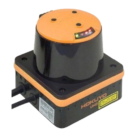
HOKUYO AUTOMATIC UXM-30LAH-EWA User manual

Document No: C-41-02567
Scanning Laser Range Finder
UXM-30LAH-EWA
User’s Manual
)

Document No: C-41-02567
1
1. Introduction.................................................................................................................................................3
1.1 About this document/manual................................................................................................................3
1.2 Applicable product ................................................................................................................................3
1.3 Special markings and symbols .............................................................................................................3
1.4 Cautions..................................................................................................................................................4
1.5 Registered trademarks..........................................................................................................................4
2. Safety precautions .......................................................................................................................................5
2.1 General precautions ..............................................................................................................................5
2.2 Operating environment .......................................................................................................................5
2.3 Installation of UXM...............................................................................................................................5
2.4 Wiring ...................................................................................................................................................6
2.5 Configuration.........................................................................................................................................6
2.6 Inspection and maintenance ...............................................................................................................6
3. Product overview.........................................................................................................................................7
3.1 Features of UXM-30LAH-EWA ...........................................................................................................7
3.2 UXM-30LAH-EWAcomponents..........................................................................................................8
3.3 Operation principle ...........................................................................................................................10
3.4 Area configuration...............................................................................................................................12
3.5 Area switching......................................................................................................................................13
3.6 Detection condition..............................................................................................................................14
3.7 ON delay/OFFdelay............................................................................................................................15
3.8 Hysteresis of detection area................................................................................................................17
3.9 Setting of UXM....................................................................................................................................19
3.10 Output ................................................................................................................................................21
3.10.1 Detection Output 1 to Output 3..................................................................................................21
3.10.2 Malfunction output.....................................................................................................................21
3.10.3 Synchronous output....................................................................................................................21
3.10.4 Synchronous master output.......................................................................................................22
3.11 Input....................................................................................................................................................22
3.11.1Area Input 1 to Input 4...............................................................................................................22
3.11.2 Synchronous Input......................................................................................................................22
3.12 Indicator lamp ...................................................................................................................................23
4. Application examples of the UXM...........................................................................................................24
4.1 Obstacle detection ..............................................................................................................................24
4.2 Access protection .............................................................................................................................25
5. Installation.................................................................................................................................................26
Table of contents

Document No: C-41-02567
2
5.1 Caution for installation.......................................................................................................................26
5.2 Optical axis adjustment ......................................................................................................................27
5.3 Light interference................................................................................................................................27
5.4 Mutual intreference.............................................................................................................................28
5.5 Synchronous operation .......................................................................................................................29
5.5.1 Example of phase setting................................................................................................................30
6. Wiring.........................................................................................................................................................32
6.1 Precautions...........................................................................................................................................32
6.2 Power supply........................................................................................................................................32
6.3 Wire colour and function....................................................................................................................33
6.4 Input/Output circuit............................................................................................................................34
6.4.1 Input circuit ....................................................................................................................................34
6.4.2 Output circuit..................................................................................................................................34
6.5 Interface connector...............................................................................................................................35
7. Setting of Area Designer .........................................................................................................................36
7.1 Area Designer.......................................................................................................................................36
7.2 System requirements...........................................................................................................................36
8. Communication .........................................................................................................................................38
8.1 Ethernet setting....................................................................................................................................38
8.1.1 Initial value....................................................................................................................................38
8.1.2 IP Initialization .............................................................................................................................38
8.2 Communication protocol ....................................................................................................................39
8.3 Error code table...................................................................................................................................39
8.4 Detail on measurement values............................................................................................................39
9. Inspection and maintenance ...................................................................................................................40
9.1 Pre-operation inspection.......................................................................................................................41
9.2 Operation inspection.............................................................................................................................41
9.3 Daily inspection......................................................................................................................................42
9.4 Periodical inspection .............................................................................................................................43
9.5 Cleaning the optical window.................................................................................................................44
10 Trobleshooting ..........................................................................................................................................45
11. Specification.............................................................................................................................................47
12. Applicable directives and standards ......................................................................................................49
13. Package contents ...................................................................................................................................50
14. External dimension..................................................................................................................................51
15. Revision history.......................................................................................................................................52
16. Represntative contacts............................................................................................................................53

Document No: C-41-02567
3
1. Introduction
This user’s manual is designed with the purpose of providing guidelines and instructions for the machine
user or system designer while operating, installing, wiring and servicing the UXM-30LAH-EWAsensor.
1.1 About this document/manual
The UXM’s features, installation and handling method are described in this document.
Make sure to read carefully and understand this document before installation, wiring, operation,
inspection and maintenance.
User should have a copy of this document at an easy-to-access place for quick reference.
Any modifications or disassembly of the UXM is prohibited. Modifications will affect sensor
performance and detection capability that could lead to critical injury and death.
Any modifications or disassembly of the UXM will void the warranty.
All information in this user’s manual is subject to change without prior notice. For the latest
information visit our company’s website http://www.hokuyo-aut.jp
1.2 Applicable product
This document is for the following sensor model.
UXM-30LAH-EWA
1.3 Special markings and symbols
Markings and symbols are used in this document to alert the user about safety-related issues. Follow the
instructions of these special markings and symbols to ensure safety during the operation.
Mark
Meaning
Procedures that could lead to dangerous situation, critical injury or death if not
carried out properly.
Procedures that could lead to dangerous situation, serious injury or physical
damage if not carried out properly.
Points that should be considered for the proper operation.

Document No: C-41-02567
4
1.4 Cautions
The UXM has been shipped upon strict quality control. If you find any defect in the product, contact the
nearest distributor or sales representative.
Hokuyo cannot be held responsible for damages or failure due to misuse of the product.
The actual product may differ from the illustrations and figures in this documents as they are used for
explanatory purpose only.
1.5 Registered trademarks
MicrosoftⓇ, WindowsⓇare the registered trademarks of Microsoft Corporation USA.
PentiumⓇare the registered trademarks of Intel Corporation or respective country.
Beside that, other product names, company name mentioned are trademarks or registered trademarks of
their respective companies.

Document No: C-41-02567
5
2. Safety precautions
Make sure to read the following safety precautions for the correct use and operation of the UXM.
2.1 General precautions
The UXM uses laser radiation for detecting objects within configured area.
Perform pre-operation tests in order to verify the performance of the UXM.
User should prepare test pieces for detection capability verification test. The test piece should emulate
the smallest object that is intended to be detected during operation.
Operate the UXM within the specifications described in this user’s manual. Also, perform the necessary
maintenance to prevent deterioration of UXM’s detection capability. (Refer to chapter 9)
Do not modify or disassemble the UXM. This could compromise the IP67 housing rating. Such
modifications will void the warranty.
The UXM is not a safety device. Do not use this sensor for the purpose of protecting humans.
The detection capability of the UXM will decrease if dust covers the optical window. Regular cleaning
of the optical window is necessary while working under dusty environment.(Refer to section 9.5)
The UXM should be disposed as industrial waste or in accordance with the local disposal directives.
2.2 Operating environment
Make sure that the UXM’s operating environment is within the stated specification (temperature,
humidity, vibration, ambient light, etc.)
Do not use or mount the UXM near devices that could generate strong electromagnetic waves as it
could affect the operation of the sensor.
Do not use or mount the UXM in an environment of organic solvents, gas, or where corrosive
substances are present. Working under such environments may decrease the detection capacity of the
sensor.
2.3 Installation of UXM
Install the UXM on a firm surface or structure to avoid displacement.
Mount the sensor firmly to avoid optical axis displacement due to vibration and shock.
Shock and vibration should not loosen the mounting. Detection result will be different if the sensor is
displaced due to such condition.
Mutual interference can occur when two or more UXM sensors are mounted at the same detection plane.
Refer to chapter 5 (mutual interference and synchronous operation) for details.
When using outdoors add necessary measures to prevent from rain and/or dust accumulation on the
optical window.
When cover is used it should be of highly transparent material that does not influence detection property.
(Light wavelength 905nm)
The UXM should be mounted with a provision of sufficient space for maintenance.
Do not put any object in the detection area of the UXM. It is not possible for the sensor to detect objects

Document No: C-41-02567
6
that lie behind the obstacle.
Increasing the response time will also increase the stability of the UXM. However, this will reduce the
detection capability towards moving objects. User must perform pre-operation tests before using this
function.
2.4 Wiring
Switch off all the power supplies during wiring.
When a converter is used for supplying the power, make sure it fulfills the following requirements.
・A rated output voltage within the range of DC 10V to 30V.
・Use power source with 1A or more (1.5A or more DC 15V or less) current capacity.
While using the heater additional 1A or more is required.
・The power supply complies with the requirements of electromagnetic compatibility regulations
(EMC) of the respective country, states and district.
All the input/output signal cables should be installed away from machines, power lines and high-
voltage cables.
2.5 Configuration
Pre-operation test must be performed to verify the configurations before operating the UXM.
Changes made during the configuration must be recorded and saved.
2.6 Inspection and maintenance
User must perform inspection and maintenance by referring to the following checklists provided in this
document. (Refer to chapter 9)
・Pre-operation inspection
・Operation inspection
・Daily inspection
・Periodical inspection
・Cleaning the optical window
Checklists in this document are provided as the basic guidelines while performing the test and maintenance.
User must perform additional inspection and maintenance tasks deemed necessary for the respective
application.
Stop the machine and system if faults are detected during these tests.
Clean the optical window when it gets contaminated. If the optical window is damaged it should be
replaced by a new one, therefore contact the nearest distributor or sales representative.

Document No: C-41-02567
7
3. Product overview
UXM emits pulsed laser beam which reflect on a rotating mirror within the configured area. When the
emitted laser beams are reflected back from an object its distance is measured.
This chapter describes the features and properties of the UXM-30LAH-EWA.
3.1 Features of UXM-30LAH-EWA
Detection range : Maximum 80m
(Guarantee detection range: 0.1 to 30m 90% Reflectance white Kent paper 1000mm×1500mm)
Detection angle :190°
Angular resolution : 0.125°
15 set of areas (Configurable)
Hysteresis of detection area ( 17 page)
It is possible to configure area with its origin offset from the center of scanning beam.
Easy configuration using PC installed with configuration application software (Area Designer )
Teaching function.
Minimum response time of 100ms (Configurable)
Malfunction output:Activates malfunction output according to self-diagnosis function.
Synchronize function: A maximum of 4 sensors for master/slave operation is possible ( 29 page)
ON/OFF delay function ( 15 page)
Filter function ( 19 page)
Limited detection capacity zone ( 20 page)
Minimum detection width ( 20 page)
Heater function ( 19 page)
SCIP communication protocol
UXM can be used for the following applications:
For the crane operating application, obstacle detection, position detection of container etc.
Access protection in the dangerous area, buildings (such as detection of vehicle, persons etc.)
This product is an auxiliary safeguard product only not a safety device. In the event
of a product malfunction, it could cause a serious accident so use an additional
safeguarding device such as bumpers. Also, take necessary measures such as
backup circuit etc.

Document No: C-41-02567
8
3.2 UXM-30LAH-EWA components
Figure 3-1 shows the components of UXM-30LAH-EWA
Figure 3-1 UXM-30LAH-EWA components
Figure 3-2 shows the scanning range and detection zone origin of the UXM, while figure 3-3 shows its
detection plane.
Cable connector
Interface connector
Indicator lamp
Optical window

Document No: C-41-02567
9
Figure 3-2 Scanning range and detection zone origin (Top view)
Figure 3-3 Detection plane of UXM (Front view)
95°
Scanning range
Detection zone origin
190°
63.5mm
Detection plane
89.4mm

Document No: C-41-02567
10
3.3 Operation principle
Figure 3-4 Scanning range
Figure 3-4 shows the scanning range of the UXM. The sensor emits pulsed laser beam which reflect on a
rotating mirror forming a fan-like scanning pattern over 190 ° field. Maximum detection range is 80m for
white Kent sheet. Detection range for objects of 10% diffused reflectance is 30m.
User can configure output regions 1, 2, and 3 by using the Area Designer application. When the sensor
detects an object in the configured area, corresponding detection outputs are switched to OFF.
When the emitted laser beams are reflected back from an object, its distance is measured by applying the
Time-of-Flight (TOF) principle. The duration of the reflected pulsed laser beam is taken for distance
calculation as shown below.
Where, L=Distance of the object
C=Speed of the light
T=Time difference
0°
190°
UXM
Output region 3
Output region 2
Output region 1

Document No: C-41-02567
11
The operation principle of TOF is shown in schematic diagram (Figure 3-5) below
Figure 3-5 TOF operation principle

Document No: C-41-02567
12
3.4 Area configuration
The detection area of the UXM consist the output regions 1, 2 and 3 respectively. Output 1 to Output 3
can be configured by using the Area Designer application software through an Ethernet cable. Area
configuration methods can be Independent and Dependent. A maximum of 15 sets of areas can be
configured.
For the Independent method the following shapes are supported: Polygon, Arc and Rectangle.
a) Polygon b) Arc c) Rectangle
Figure 3-6 Area configurations (Independent method)
For the Dependent method, the following shapes are defined: Straight line, Fan, and Ratio. In the
dependent method, output 1 serves as abasis for output 2. Similarly, output 2 can be set as the basis for
output 3.
a) Straight line b) Fan c) Ratio
Figure 3-7 Area configurations (Dependent method)
When setting the output region 2 as dependent on output region 1, the following dependent methods can
be selected: a) Straight line, b) Fan shape, c) Ratio. By moving the offset bar in the Y-axis, it changes the
size of output region 2.The output 2 cannot be made larger than the output 1.Similarly, the output region 3 is
used as a basis output region 2.
Output region 1
Offset bar
Output region 2

Document No: C-41-02567
13
For details on area configuration methods, refer to the Area Designer sensor configuration tool Instruction
manual.
When the sensor detects an object in the configured output region 1 to output region 3, the corresponding
outputs signals are switched to OFF state and the corresponding LEDs are also lit.
3.5 Area switching
A maximum of 15 sets of areas can be configured. For area switching, input signals 1 to 4 are required.
Table 3-1 below shows the combination of input signal to switch the area. Laser is switched off when all the
area inputs 1 to 4 are switched ON.
Table 3-1 Input states and corresponding area number
Area Number
Area Input 1
Area Input 2
Area Input 3
Area Input 4
Laser off
ON
ON
ON
ON
Area1
OFF
ON
ON
ON
Area2
ON
OFF
ON
ON
Area3
OFF
OFF
ON
ON
Area4
ON
ON
OFF
ON
Area5
OFF
ON
OFF
ON
Area6
ON
OFF
OFF
ON
Area7
OFF
OFF
OFF
ON
Area8
ON
ON
ON
OFF
Area9
OFF
ON
ON
OFF
Area10
ON
OFF
ON
OFF
Area11
OFF
OFF
ON
OFF
Area12
ON
ON
OFF
OFF
Area13
OFF
ON
OFF
OFF
Area14
ON
OFF
OFF
OFF
Area15
OFF
OFF
OFF
OFF
OFF:High level, ON:Low level
Response time:2 Scan (100ms)
●Laser is switched ON only in the selected area.
User should prepare test pieces for detection capability verification test.

Document No: C-41-02567
14
3.6 Detection condition
In the configured area, if the detectable size (width) is more than the minimum detectable objects an
output signal is displayed (for setting refer to section 3.9).The width of detectable object can be calculated
as shown in figure 3-8.
Figure 3-8 Schematic diagrams for the calculation of detection width
If the area is configured with a narrow width below the minimum detectable size, be careful that the
output signal may not be displayed for a short distance as shown in figure 3-9.
Figure 3-9 Caution of area configurations when minimum detectable size
Detection width W = (d2 + d3 + d4) ×2π/ 2880
Detection object
d1
d2
d3
d4
d5
d: Distance value of each step
Detection width W > Minimum detectable size
物
Min detectable size:100mm
Area of distance:1800mm and approx. width 100mm
Output
Input
Output
Depending upon the laser spot, environment and the detection object, the actual
width of detected objects may differ from the width measured.
User should verify detection capability before using the actual object.
Input

Document No: C-41-02567
15
3.7 ON /OFF delay
ON delay and OFF delay of the output signal can be set by using Area Designer within the range of 50ms
to 6400ms with an interval of 50ms. (Default is 50ms)
ON delay is the response time changing from ON state to OFF state after detecting the object. OFF delay is
the response time changing from OFF state to ON state while not detecting the object.
Increasing the response time will increase availability of the UXM. However, this will reduce the detection
capability towards moving objects. User must perform verification tests before using ON/OFF delay
function.
Figure 3-10 ON delay /OFF delay
Schematic diagram for ON delay/OFF delay operation is as shown below.
1. Example of schematic diagram without OFF delay setting
1scan (Object absent) 2scan (Object present)
:Object absent
:Object present
Output judgment
Output judgment
Object detection: OFF (High level)
No object detection: ON (Low level)
Sensor detection
Detection output
OFF
ON
ON delay
OFF delay
Time
Detection object

Document No: C-41-02567
16
2. Example of schematic diagram when 2 scan OFF delay setting
1scan (Object absent) 2scan (Object absent) 3scan (Object present)
3. Example of schematic diagram without ON delay setting
1scan (Object present) 2scan (Object absent)
4. Example of schematic diagram when 2 scan ON delay setting
1scan (Object present) 2scan (Object present) 3scan (Object absent)
:Object absent
:Object present
Output judgment
Output judgment
Output judgment
:Object absent
:Object present
Output judgment
Output judgment
: Object absent
: Object present
Output judgment
Output judgment
Output judgment

Document No: C-41-02567
17
3.8 Hysteresis of detection area
When a sensor detects an object near the boundary of the detection area, outputs 1 to 3 may oscillate
(Changing of ON/OFF state) repeatedly. To prevent such oscillation, sensor has a hysteresis function that
temporarily increases the area size. If the object is not detected in the temporarily increased area, then it will
return to the original detection area.
Hysteresis changes according to the set detection area distance. The minimum and the maximum
temporarily increased detection area size can be specified using Area Designer. Minimum detection value
will be used if the value is 5000mm or less. Also, maximum detection value will be used if the value is
30000mm or more. For distances between 5000mm to 30000mm; the value is computed using the linear
interpolation method from the minimum and maximum values.
Hysteresis = (Max value –Min value) / (25000) × Distance +( 6 × Min value -Max value ) / 5
Figure 3-11 Hysteresis additional value

Document No: C-41-02567
18
When you set the detection area close to a wall, set the hysteresis to the minimum value. If the
surface of the wall is within the hysteresis detecting area range, then the output will not return to
its original state.
・Judgment Area : From object absent to object present
・Judgment Area : From object present to object absent
Detection area
Detection area
Wall
Wall
Detects the wall
Judgment area
Judgment area
(Becomes large due to hysteresis)
Object
Object

Document No: C-41-02567
19
3.9 Setting of UXM
Setting of operating parameter of UXM by Area Designer.
Table 3-2 describes UXM’s parameters and settings.
Table 3-2 Parameter settings
Parameter
Description
Motor sync angle
To prevent mutual interference between the sensors, motor synchronize
angle can be set by delaying the rotation.
For details on synchronization operation, refer to chapter 5.5
Setting
0 deg
90 deg
180 deg
270 deg
Heater
Heater is internally mounted in the sensor and this function will
activate. When the temperature inside the sensor decreases below
0°C.This function stops its operation automatically when the
temperature increases more than 10°C.
Setting
Description
OFF
Cannot use heater function
ON
Can use heater function
Output logic
Invertingoutputslogicofdetectionoutput1to3canbeset.Selectfrombelowsetting.
Setting
Description
Active High
Normal detection outputs Refer to 3.10.1
Active Low
Invert detection outputs
Filters
Rain
This filter is used to remove the object if the object is not detected
stably at the same place. This filter is effective to remove rain and snow.
Select from below setting.
Setting
Reference value while using rain filter
OFF
Filter not used.
Low
Used to remove rain maximum up to approx.100mm/h.
However, theeffect dependsupontheinstallationenvironment
High
Caution: By setting therain filter, it becomes difficult to detect moving object.
Fog
This filter is used to remove reflectivity (echoes) from the fog.
Select from below setting.
Setting
Reference value while using fog filter
OFF
Filter not used.
Low
Used in fog when the visibility is approx.100m.
However, the effect depends upon the installation
environment
Medium
High
Caution: By setting the filter high, it may not also detect the
objects with high reflectivity.
Other manuals for UXM-30LAH-EWA
1
Table of contents
Other HOKUYO AUTOMATIC Measuring Instrument manuals
Popular Measuring Instrument manuals by other brands

ASTi
ASTi IOTRON Installation guide & user manual

ATAGO
ATAGO PAL-54S instruction manual

Emerson
Emerson Clarity II instruction manual

MesaPhotonics
MesaPhotonics VideoFROG FROGscan user manual

Extech Instruments
Extech Instruments 850 OWL quick guide

Tektronix
Tektronix TekSmartLab TBX3000A Installation and safety instructions