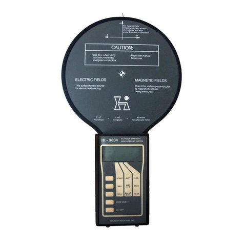
Holaday Industries HI-3624 User manual

HI-3624 / HI-3624A
ELF Magnetic Field Meter
User's Manual
Copyright ©1991 Holaday Ind. Inc.
Manual #600044 04/91 $8.50


Revision Record
Manual #600044
HI-3624 / HI-3624A ELF Magnetic Field Meter
Revision Description Date
--- Release 4/91
AAdded CE label, updated 1/00


TABLE OF CONTENTS
Description ................................ 1
Specifications .............................. 3
Operation ................................. 5
Example Applications ......................... 9
Power Lines ........................... 9
VDTs ...............................10
Residential ............................11
References ................................13


LIMITED WARRANTY
HOLADAY INDUSTRIES, INC. WARRANTS EACH MODEL HI-3624 / HI-
3624A POWER FREQUENCY FIELD STRENGTH METER TO BE FREE FROM
DEFECTS IN MATERIAL AND WORKMANSHIP FOR A PERIOD OF ONE
YEAR FROM DATE OF SHIPMENT TO THE PURCHASER. THIS WARRANTY
EXTENDS TO THE ORIGINAL PURCHASER ONLY AND DOES NOT APPLY
TO BATTERIES OR ANY PRODUCT OR PARTS SUBJECT TO MISUSE,
NEGLECT, ACCIDENT, UNAUTHORIZED SERVICE OR ABNORMAL
CONDITIONS OF OPERATION.
IN THE EVENT OF INSTRUMENT FAILURE COVERED BY THIS WARRANTY,
HOLADAY INDUSTRIES, INC. WILL, WITHOUT CHARGE, REPAIR AND
RECALIBRATE THE INSTRUMENT IF RETURNED TO THEIR FACTORY
WITHIN ONE YEAR OF THE ORIGINAL PURCHASE, PROVIDED THAT
HOLADAY INDUSTRIES' EXAMINATION DISCLOSES TO ITS
SATISFACTION THAT THE PRODUCT WAS DEFECTIVE. HOLADAY
INDUSTRIES, INC. MAY, AT ITS OPTION, REPLACE THE PRODUCT IN
LIEU OF REPAIR. IF THE DEFECT WAS CAUSED BY MISUSE, NEGLECT,
ACCIDENT, UNAUTHORIZED SERVICE OR ABNORMAL CONDITIONS OF
OPERATIONS, REPAIRS WILL BE BILLED AT ANOMINAL COST. IN SUCH
CASE, AN ESTIMATE WILL BE PROVIDED BEFORE WORK IS STARTED IF
REQUESTED BY THE PURCHASER.
FOR WARRANTY SERVICE, CONTACT HOLADAY INDUSTRIES, INC.
GIVING FULL DETAILS OF THE FAILURE AND THE SERIAL NUMBER OF
THE INSTRUMENT. YOU WILL THEN BE GIVEN SERVICE INFORMATION
OR SHIPPING INSTRUCTIONS. RETURN THE INSTRUMENT TO THE
FACTORY TRANSPORTATION PREPAID. REPAIRS WILL BE MADE AT THE
FACTORY AND THE INSTRUMENT RETURNED TO YOU TRANSPORTATION
PAID. HOLADAY INDUSTRIES, INC. ASSUMES NO RESPONSIBILITY FOR
LOSS OF, OR DAMAGE TO, PRODUCTS IN TRANSIT.
WARNING
SPECIAL CAUTION IS ADVISED WHEN WORKING IN ENVIRONMENTS
WHERE CONTACT WITH HIGH VOLTAGE OR HIGH CURRENT CIRCUITS OR
APPARATUS IS POSSIBLE. THIS IS PARTICULARLY TRUE WHEN
ATTEMPTING TO OBTAIN ELECTRIC OR MAGNETIC FIELD STRENGTH
MEASUREMENTS IN CONFINED QUARTERS, FOR EXAMPLE INSIDE
CABINETS CONTAINING ELECTRICALLY OPERATED EQUIPMENT,
ELECTRIC POWER SUBSTATIONS OR IN VERY CLOSE PROXIMITY TO THE
CONDUCTORS OF ENERGIZED POWER LINES. ACCIDENTAL CONTACT
WITH OBJECTS OR CIRCUITS OPERATED AT HIGH VOLTAGES OR HIGH
CURRENTS CAN BE LETHAL! HOLADAY INDUSTRIES, INC. ASSUMES NO
LIABILITY FOR DAMAGES OR PERSONAL INJURY WHICH MAY RESULT
FROM ACCIDENTS ARISING OUT OF USE OF THIS EQUIPMENT.


HI-3624 / HI-3624A Manual Page 1
Description
The HI-3624 ELF Magnetic Field Meter is designed to measure
the flux density of magnetic fields in the frequency range of 30
Hz to 2 kHz. The Model HI-3624A provides for a switch
selectable measurement range from 5 Hz to 2 kHz to conform
with recent measurement guidelines issued in Sweden for
extremely-low-frequency (ELF) magnetic fields produced by
video display terminals (VDTs). The HI-3624 finds application
in the measurement of magnetic fields associated with electric
power lines, electrically operated appliances and VDTs.
The HI-3624 is asingle axis flux density meter designed to be
responsive to either sinusoidal or complex magnetic field
waveforms such as produced by the vertical deflection systems
of VDTs. It directly displays the root-mean-square (rms) value
of magnetic flux density on an analog meter. The sensor
consists of a multiturn loop connected to the instrumentation
readout package via aone meter long cable. The separate loop
sensor provides for orientation of the sensor relative to the
various magnetic field polarization components. This allows
quick assessment of the greatest flux density value while
conveniently holding the instrument for easy meter reading.
This feature makes the HI-3624 especially useful for rapid, large
area surveys of magnetic fields.
The field sensor loop is electrically shielded so that the response
of the HI-3624 is solely due to magnetic fields. No interference
is caused by ambient strong electric fields such as might be
found beneath high voltage, overhead electric power lines or
nearby radio or television stations.
The HI-3624 has a wide dynamic measurement range. This
provides for full scale ranges of as small as 2 milligauss to as
great as 20 Gauss. This large dynamic range makes the
HI-3624 convenient for measurement of ambient residential
magnetic fields as well as high level fields found near high
current carrying conductors or electrical machinery.

Page 2 HI-3624 / HI-3624A Manual
Model HI-3624
ELF Magnetic Field Meter

HI-3624 / HI-3624A Manual Page 3
Figure 1
Specifications
Frequency Response:
30*to 2000 Hz Flat
30*Hz - 3 dB
2000 Hz - 3 dB
< 30*Hz Falling 80 dB/decade
> 2000 Hz Falling 40 dB/decade
*(Note: This frequency switchable to 5 Hz on
HI-3624A see figure 1)
Sensor:
External, multi-turn loop, with inside diameter of 110
mm and outside diameter of 116 mm; area of loop is
0.010 square meters. Cable length is 1.2 meter.
Detector Response:
True rms field indication for accurate measurement of
non-sinusoidal waveforms.
Sensitivity:
Full scale ranges of:
2 mG;
20 mG;

Page 4 HI-3624 / HI-3624A Manual
200 mG;
2 G;
20 G.
Accuracy:
Within ± 5 % at calibration frequencies of 50, 100,
500 and 1000 Hz.
Power:
Two (2) nine volt alkaline batteries
(NEDA 1604A, Duracell MN1604 or equal).
Battery Life:
Up to 120 Hours Intermittent use.
Linearity:
2% on HI-3624A (5% on HI-3624)
Instrument accuracy is derived from a field calibration using a
one meter diameter pair of Helmholtz coils for establishing an
accurately known magnetic field flux density. A precisely
controlled and measured sinusoidal current is driven through the
Helmholtz coils and, based on the dimensions of the coils, the
magnetic field flux density between the coils in milligauss (mG)
is calculated.
While the HI-3624 indicates magnetic flux density (B) in units
of milligauss, the flux density in microtesla or magnetic field
strength (H) in milliamperes per meter may be obtained via the
following relations:
1 microTesla = 10 mG
1 mG = 80 milliamperes per meter (mA/m)

HI-3624 / HI-3624A Manual Page 5
Operation
The ELF magnetic field sensor must be plugged into the HI-3624
meter case for proper operation; it makes no difference whether
the sensor is plugged in before or after the meter is turned on.
Asingle switch controls the entire operation of the HI-3624
(except for the model HI-3624A, in which case one additional
switch controls the desired low frequency cutoff). The main
switch turns on the instrument and selects one of five ranges
for measurement. A "Low Battery" LED glows when the
batteries are low. If the "low Battery" indicator remains on
replace both of the batteries which are accessible from the back
side of the meter case. It is normal for the LED battery indicator
to briefly blink during turning the switch to various ranges and
when turning the instrument off.
When beginning field measurements, successively turn the
range switch to the right, increasing the instrument's sensitivity
until an upscale reading on the meter is obtained. Most accuracy
is achieved when the meter reads approximately midscale. At
each range setting, while holding the meter in one hand, rotate
the sensor with the other hand so as to obtain a maximum
indication on the meter.
Because the sensor is capable of measuring only one polarization
component of the magnetic field at any specific time, there are
two methods that can be used for measurements. In the
majority of cases, it is sufficient to orient the sensor so that a
maximum indication on the meter is observed. In many
instances this will be ameasurement of the resultant magnetic
flux density. The sensor must be rotated about three axes
which are each perpendicular to one another. This can be
quickly accomplished with a little practice.
In other cases, the root-sum-squared resultant value of flux
density may be obtained by taking three orthogonal
measurements of the field; in this case, the sensor is
successively oriented in three mutually perpendicular directions
around afixed point and the individual readings recorded. The
mutually perpendicular directions will be denoted as X,Y, and Z.
The resultant flux density is then found by forming the root-
sum-squared value from the individual readings as follows:

Page 6 HI-3624 / HI-3624A Manual
B = (Bx
2+ By
2+ Bz
2)1/2 where
B = resultant flux density;
Bx= Reading in the X direction;
By= Reading in the y direction;
Bz= Reading in the Z direction.

HI-3624 / HI-3624A Manual Page 7
Figure 2
It does not matter which orientation of the field sensor is used
for the xorientation but the yand zorientations must be
perpendicular to one another and the xorientation. Figure 2
illustrates one possibility for the three mutually orthogonal
orientations. This figure shows a sensor VDT separation
distance of 30 cm. The 30 cm spacing is commonly used in
VDT measurements but alternative distances may also be used.
In the case of the Model HI-3624A, the user may select the
lower frequency of the band pass for the instrument as either
30 Hz (the value incorporated in the Model HI-3624) or 5Hz as
specified in the Swedish standard for measurements of
magnetic fields produced by VDTs. It should be noted that
when the instrument is switched to the 5 Hz lower frequency
cutoff, the unit will be very sensitive to motion of the sensor
since movement within the earth's constant field will appear as
asignal to the instrument. When the sensor is accelerated or

Page 8 HI-3624 / HI-3624A Manual
rotated within aconstant field, there will be an output from the
sensor at afrequency corresponding to the movement and this
will usually include frequency components greater than 5 Hz.
Consequently, during such movement, the meter will typically
show significant upscale indications. The 5 Hz frequency cutoff
setting is primarily useful for measurements at fixed coil
positions such as near VDTs, in which case the sensor is not
being moved. For area surveys of ELF fields, the 30 Hz cutoff
will be more useful.

HI-3624 / HI-3624A Manual Page 9
Figure 3
Example Applications of the HI-3624/HI-3624A
Power Lines
Magnetic fields near power lines can be easily measured with
the HI-3624. An approach commonly used to characterize
power line fields is to measure the flux density along astraight
line which passes perpendicular to the power line. Generally,
readings are first taken along the length of aspan of the power
line to identify the point at which the greatest flux density
exists. Then at this point take the readings perpendicular to the
power line. Take readings every five to ten feet and orient the
sensor for maximum reading. A magnetic field flux density
profile can then be developed. This method is outlined by the
Institute of Electrical and Electronics Engineers (IEEE) in the
American National Standards Institute (ANSI) standard
644-1987 (1).
Figure 3is an example of atheoretical profile obtained for a230
kilovolt (kV), single circuit line with 1000 amperes flowing in
the conductors. For the particular case presented, the
conductors are situated 50 feet above ground and are spaced
32 feet apart. The actual profile shape is dependent on the
exact geometry of the power line, its height above ground and
the current flowing in the line. The flux density peaks near a
point beneath the conductors of the line.

Page 10 HI-3624 / HI-3624A Manual
Asimilar approach may be used for measuring the flux density
produced by buried lines. In this case, the area must be
explored by walking about with the meter, simultaneously
moving the sensor in various orientations, until the region of
maximum flux density is found.
VDTs
VDTs produce ELF magnetic fields which come about from the
circuitry within the VDT which deflects the electron beam
vertically in the cathode-ray-tube (CRT). ELF fields will also be
generated by the power transformer within the VDT. The
magnetic fields are used to deflect the beam and are saw-tooth
in shape with frequencies ranging approximately between 45 Hz
and 75 Hz, depending on the particular design of the VDT. The
HI-3624 is designed to properly detect these magnetic fields
because of its rms detector and wide bandwidth.
Two different methods for VDT magnetic field measurements
have been commonly used. The first is that of characterizing
the field at a fixed distance from the screen of the VDT.
Conventionally, distances of 30 cm and 50 cm have been used
for such measurements. Normally, the measurements are taken
from the front surface of the screen. Additional measurements
may be taken relative to the sides, the top and the back of the
VDT to explore the distribution of the fields about the VDT.
The second method involves a measurement at the position of
the VDT operator to assess the flux density to which the
operator is actually exposed while sitting at the VDT. Because
different individuals will sit at different locations and have
different postures, the operator exposure measurement may be
more afunction of the operator than of the specific VDT. A
reasonable approach for the operator exposure measurement is
to position the sensor at a point corresponding to where the
center of the body would be located during operation of the
VDT.
In performing VDT measurements, it is important to note that
the magnetic fields decrease very rapidly with increasing
distance from the screen. Because of this characteristic, it is
important to insure that the position of the sensor is precisely
known. Attempts to repeat the measurement results will be
hampered by unnecessary variability if the sensor is not replaced
at the same exact position. Spacing measurements should be
made from the VDT surface to the center of the sensor. The
center of the sensor is indicated by the target symbol.
The Model HI-3624A contains circuitry to extend the lower

HI-3624 / HI-3624A Manual Page 11
frequency response down to 5 Hz in accordance with
recommendations used for VDT measurements in Sweden. The
user is referred to the Swedish specifications for measurement
(2) for application details.
Residential Measurements
Magnetic fields found in home environments are highly variable,
depending on location within the home. This variability is
strongly related to the distribution of the wiring in the home, the
location of electrical appliances and, sometimes, the location of
plumbing lines or other metallic structures within the ground
which may form low resistance paths for electrical ground
return currents. Establishing what the ambient magnetic field
environment is in a home usually requires numerous
measurements throughout the home, with at least one
measurement within each room. Normal practice would include
at least one field measurement taken near the center of each
room. A more thorough approach would include five
measurements in each room, one at the center and one near
each corner of the room. A reasonable technique is to position
the sensor at apoint approximately one meter from each room
corner for the flux density measurement. This avoids, to an
extent, placing the sensor immediately next to wiring which
may be hidden within the walls of the room and which may
yield unrealistically high values of flux density compared to what
most individuals within the room might be exposed.
Surveys of the areas near electrical appliances will usually reveal
higher values of flux density due to the currents flowing within
motors or heating elements. Logical choices would include the
location of beds, for example, since this is a location of
extended occupancy. In characterizing the magnetic fields near
obvious sources, such as appliances, it is often helpful to
measure and record the flux density value at intervals of afew
inches (or centimeters) beginning near the surface of the device.
These data will help provide aperspective on the spatial extent
of the elevated field levels and the significance of the levels
relative to other values determined elsewhere within the home.
Field measurements should take into account the likelihood that
individuals may have access to areas where measurements are
contemplated.
Because 60-Hz magnetic fields produced by the use of
electricity within the home are dependent on the magnitude of
current flowing within wires or the operation of appliances, flux
densities will be seen to vary with time, being greater when
more electrical power is being used. For example, when heating

Page 12 HI-3624 / HI-3624A Manual
or air conditioning systems turn on or the compressor within a
refrigerator cycles on, the flux density will increase.
Measurements must take this condition into account and it is
recommended that, when taking measurements in aroom, the
meter be watched for a period of time to observe for
fluctuations in the indicated value of flux density. After some
experience, it may be possible to relate the observed
fluctuations to various uses of electricity within the home.
Aphenomenon which has recently received some attention in
regard to residential magnetic fields is the flow of earth currents
via plumbing lines or telephone cables buried beneath the
home. In some cases, it has been noted that 60-Hz magnetic
fields exist within ahome, even when the home is not using any
electrical power (the circuit breakers have all been turned off at
the main electrical service box of the home).
This observation has, in some cases, been related to the flow of
currents beneath the home on pipes or cables. It is not unusual
for currents, related to other neighbors' use of electricity, to
flow back to the electrical supply via low resistance paths
formed by metal plumbing pipes or wires used for telephones as
opposed to the electrical system neutral wire. In such cases, it
is possible to measure magnetic flux densities within the home
without any apparent reason if the power to the home has been
shut off.
This manual suits for next models
1
Table of contents
Other Holaday Industries Measuring Instrument manuals
Popular Measuring Instrument manuals by other brands

HT
HT HT4011 user manual

Spectroline
Spectroline Accupro XP-2000 quick guide

LASER COMPONENTS
LASER COMPONENTS Viavi HP3-60-P4 quick start guide

Demtech
Demtech Pro-Tester T-0100 Operator's manual

Xylem
Xylem YSI 2500 user manual

PCB Piezotronics
PCB Piezotronics IMI Sensors Spindler 607A61 Installation and operating manual

IS Technologies
IS Technologies SLM800S user manual

WILDLIFE
WILDLIFE AquaPulse Impulse Counter quick start guide

Tatsuta Electric Wire & Cable
Tatsuta Electric Wire & Cable AD-AS-10DRM Operation manual

FISCHER
FISCHER DS21 operating manual

Makita
Makita LVH800 manual

GANN
GANN HYDROMETTE BL H 41 Operation instructions