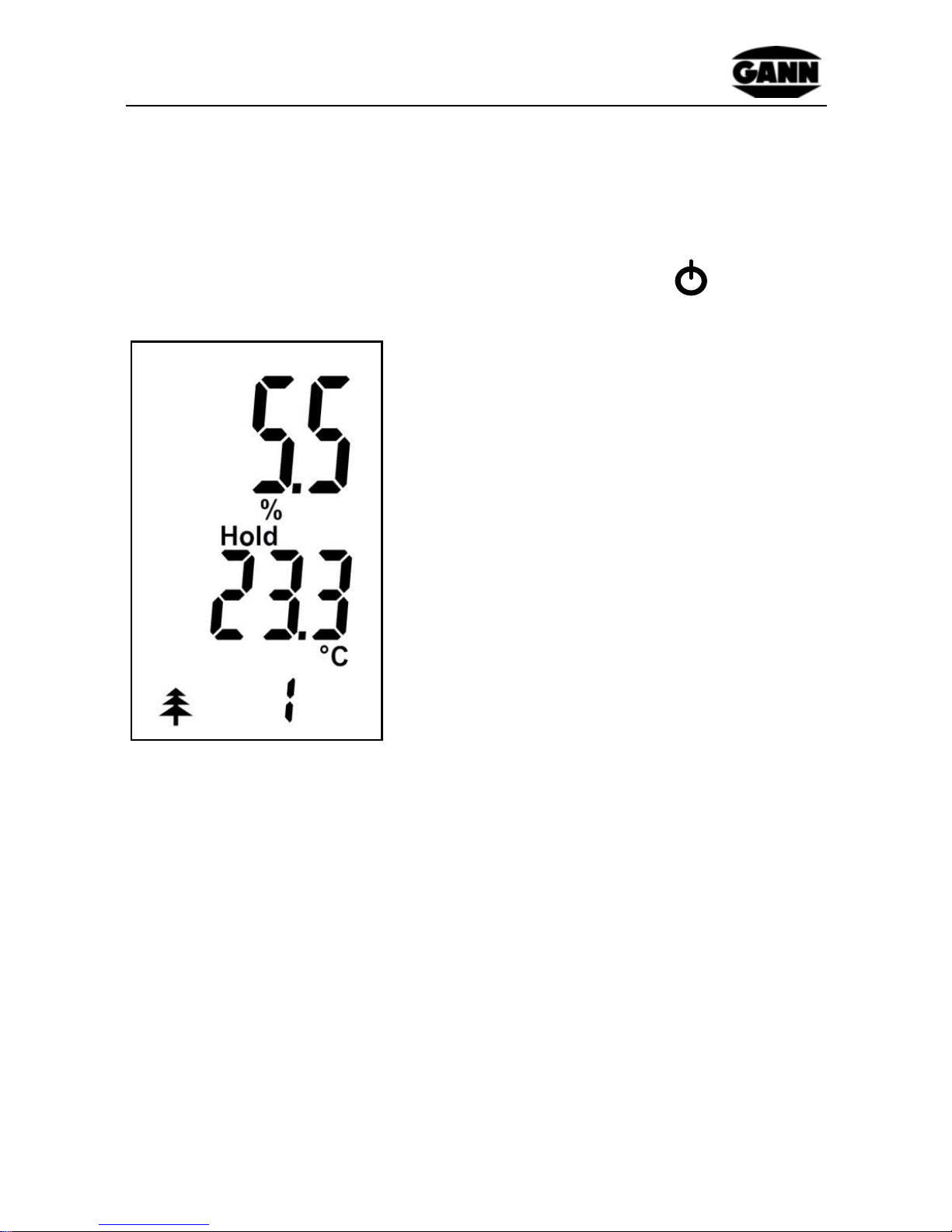
GANN HYDROMETTE BL H 41 User manual

1
Hydromette BL H 41
HYDROMETTE BL
H 41
Operation instructions
Version 1.1

2
Hydromette BL H 41
Table of contents
0.1 Publication statement........................................................ 4
0.2 WEEE directive 2002/96/EC law on electrical and
electronic equipment ........................................................4
0.3 General notes....................................................................5
0.4 Safety advice.....................................................................6
1Introduction.......................................................................... 7
1.1 Description.........................................................................7
1.2 Device layout and button assignment................................8
1.3 Display symbols.................................................................9
2Basic functions.................................................................. 10
2.1 Switch on device.............................................................. 10
2.2 Display in measuring mode ............................................. 11
2.3 Setting menus.................................................................. 11
2.3.1 Measurement menu (main menu)....................... 12
2.3.2 Material setting................................................... 13
2.3.3 Temperature compensation................................ 15
2.3.4 Maximum value display...................................... 16
2.3.5 Minimum value display....................................... 17
2.3.6 Memory menu .................................................... 18
2.4 Other functions................................................................ 19
2.4.1 Automatic switch-off ........................................... 19
2.4.2 Battery monitoring .............................................. 19
2.4.3 Changing the electrode pin................................. 19

3
Hydromette BL H 41
3Specifications..................................................................... 20
3.1 Technical data................................................................. 20
3.2 Prohibited environmental conditions................................ 20
3.3 Measuring ranges............................................................ 21
4Application notes............................................................... 21
4.1 Notes on measuring wood moisture................................ 21
4.1.1 Introduction......................................................... 22
4.1.1.1 M 20 hammer-in electrodes................................ 23
4.1.1.2 M 20-OF 15 surface measuring caps ................. 23
4.1.1.3 Push-in electrode M 19....................................... 24
4.1.1.4 M 20-HW 200/300 stick-in electrode pair............ 24
4.1.1.5 Ram-in electrode M 18....................................... 24
4.1.2 Equilibrium wood moisture content..................... 26
4.1.3 Growth ranges of fungi....................................... 26
4.1.4 Swelling and shrinkage of the wood................... 26
4.2 Measurements on wood fibre insulating boards .............. 27
4.2.1 Introduction......................................................... 27
4.2.2 Handling............................................................. 27
4.3 Test adapter for wood moisture measurement................ 29
4.4 Static charge.................................................................... 29
5Table of wood types .......................................................... 30
6Appendix: Accessories ..................................................... 31
6.1 Wood moisture measurement.......................................... 31
6.2 Wood fibre insulating materials........................................ 32

Introduction
4
Hydromette BL H 41
0.1 Publication statement
This publication replaces all previous versions. It may not be
reproduced in any form or processed, duplicated or disseminated
using electronic systems without the written permission of Gann
Mess- u. Regeltechnik GmbH. Subject to technical and
documentary changes. All rights reserved. This document was
prepared with the required care. Gann Mess- u. Regeltechnik
GmbH accepts no liability for errors or omissions.
GANN Mess- u. Regeltechnik GmbH, Gerlingen, Germany.
06.07.15
0.2 WEEE directive 2002/96/EC law on electrical
and electronic equipment
Disposal of packaging, the battery and the device must be
undertaken in accordance with the legal requirements at a recycling
centre.
The device was manufactured after 1 October, 2009

Introduction
5
Hydromette BL H 41
0.3 General notes
This measuring device fulfils the requirements of the applicable
European and national directives (2004/108/EC) and standards
(EN61010). Appropriate declarations and documentation are held
by the manufacturer. To ensure trouble-free operation of the
measuring device and operational reliability, the user must carefully
read the operating instructions. The measuring device may only be
operated under the climatic conditions specified. These conditions
can be found in section 3.1 "Technical data". This measuring
device may likewise only be used under the conditions and for the
purposes it was designed for. Operational reliability and
functionality are no longer ensured if the device is modified or
adapted. Gann Mess- u. Regeltechnik GmbH is not liable for any
damage arising from such modifications or adaptations. The risk is
borne by the user alone.
The device must not be stored or operated in aggressive
air or air containing solvents!
Static charge - at low levels of air humidity aided by
external factors (friction during material transport, high
insulation of the surrounding area), static electricity can
build up with high voltages, which can not only lead to
strong swings in measured values or minus values, but
also to the destruction of electrical components in the
device. The operator of the measuring device can also,
unintentionally, contribute to the build-up of static charge
from his/her clothing. A significant improvement can be
achieved by ensuring the operator and the measuring
device remain completely still during the measurement
process and by earthing (touching conducting metal, water
or heating pipes, etc.).
Frozen wood cannot be measured.

Introduction
6
Hydromette BL H 41
The notes and tables in these instructions on permitted or
normal humidity conditions in practice and the general
definitions of terms have been taken from the specialist
literature. No responsibility can therefore be taken by the
manufacturer for the correctness of this information. The
conclusions to be drawn from the measurement results
are related to the individual conditions and the knowledge
drawn from professional experience for each user.
The measuring device may be operated in residential and
commercial areas, as the stricter class B for emitted
interference (EMC) has been adhered to.
The measuring device and any accessories may only be
properly used as described in these instructions. Keep the
device and accessories out of the reach of children!
Wood and other materials should not be measured on
conductive surfaces.
Gann Mess- u. Regeltechnik GmbH accepts no liability for damage
resulting from non-adherence to the operating instructions or by not
taking proper care during transport, storage and handling of the
device during operation, even if this requirement for care is not
specifically addressed in the operating instructions.
0.4 Safety advice
WARNING: There is a risk of injury from the measurement
probes of the electrodes. Before inserting the electrode pins into
wooden panels or similar, use suitable methods to ensure that
there are no electrical wires, water pipes or other supply lines at
this point.

Introduction
7
Hydromette BL H 41
1 Introduction
1.1 Description
The Hydromette BL H 41 is an electronic wood moisture measuring
device for precise measurement of sawn timber (up to 180 mm
thick), chipboard and veneers with a high-quality measurement
amplifier and 3-line LCD display.
The device has a wood type switch to automatically correct
measurement values for over 300 types of wood as well as wood
temperature compensation.
The M20 electrode is inserted into the respective material to be
measured and allows the measurement of moisture in sawn timber,
chipboard, veneers and wood fibre materials up to 180 mm thick
(with electrode M 18).

Introduction
8
Hydromette BL H 41
1.2 Device layout and button assignment
Electrode connection
Display
Up button
On/off button
Measurement button
Down button

Introduction
9
Hydromette BL H 41
1.3 Display symbols
Main menu symbols
Wood moisture
Measured value is held.
Ready for measurement
Device temperature in °C
Wood type classification
number
Wood symbol
Other symbols
Min/Max display
Wood moisture
Battery symbol
Compensation
temperature "c" in °C
Wood symbol

Basic functions
10
Hydromette BL H 41
2 Basic functions
2.1 Switch on device
The device is switched on by pressing the On button .
Last measured value in %
"Hold" symbol
Last measured device temp. in °C
Wood symbol and classification
number
In this menu, a new measurement can be started by pressing the
measurement button "M". See also section 2.2 "Measuring mode".
Figure 2-1 Main menu

Basic functions
11
Hydromette BL H 41
2.2 Display in measuring mode
Displayed measured value in %
"Hold" symbol indicates readiness
to make a measurement
Device temperature in °C
Wood symbol and classification
number
A measurement process is started by pressing the "M" button.
2.3 Setting menus
The following menus can be selected one after the other by
repeated pressing of the "Up" and "Down" buttons. On the
following page, the sequence of the setting menus that is seen by
pressing the "Down" button is shown.
1. Measurement menu (main menu): Use to carry out the
measuring process.
2. Wood type setting: The wood type can be selected here.
3. Temperature menu: The temperature compensation can
be set here.
Figure 2-2 Measurement mode

Basic functions
12
Hydromette BL H 41
4. Maximum value display: The highest value measured is
shown here.
5. Minimum value display: The lowest value measured is
shown here.
6. Memory menu: The last 5 values measured can be called
up here.
2.3.1 Measurement menu (main menu)
The last measurement with the note
"Hold" is shown here. The device
temperature and the current type are
also shown on the display.
In this menu, a new measurement can
be started by pressing the "M" button.
During the measuring process, the
“Hold" symbol disappears from the
display and the % symbol flashes. If
the measured value is stable, the %
symbol remains switched on, and after
releasing the "M" button the
measured value is saved. The "Hold"
symbol is displayed again.
If the new measured value is higher or lower than the previous
maximum or minimum value, "Max" or "Min" appears flashing on
the display. If the value is to be saved as the Min. or Max. value,
the "M" button must be pressed briefly. If the value is not to be
saved, a new measurement can be started with a long press on the
"M" button without changing the previous saved maximum or
minimum values.
If the measurement range is not reached or exceeded
(H 41: < 4.5%, > 45%) a flashing measured value shows a
warning, which is also alternately marked with "LO" or "HI".

Basic functions
13
Hydromette BL H 41
2.3.2 Material setting
The classification number set is
displayed with the symbol for
the wood moisture.
Wood symbol and classification
number
To carry out the material setting, the device must be switched on
and be in main measuring mode (standard mode after switching
on). After pressing once on the “Down” button, you reach the view
as shown in figure 2-3. If the preset for the material is to be
changed, the “Mbutton (measurement button) must briefly be
pressed.
The Material index flashes and can be set using the Up or Down
buttons. The change is saved by pressing the "M" button again
briefly.
The material table is found in the Appendix.
The wood types are displayed by a fir tree symbol and the
correspondingly selected type number, e.g.:
Fir tree 2 = Wood type 2
With wood fibre insulating boards, the method of manufacture for
the selected board appears in the upper area in WET and DRY. In
Figure 2-3 Wood type selection

Basic functions
14
Hydromette BL H 41
the middle and lower areas, the gross density of the selected wood
fibre insulating board is shown: e.g.: 180 / 200 = From 180 kg/m3to
200 kg/m3
Manufacturing process for the selected
wood fibre insulating board: shown as
dry here
The selected wood fibre insulating
board has a gross density from 180
kg/m3…
... to 200 kg/m3
There are 6 different characteristic curves for wood fibre insulating
boards. These can be found in the appendix.

Basic functions
15
Hydromette BL H 41
2.3.3 Temperature compensation
If the pre-set value for the compensation temperature is to be
changed, the "M" button is pressed briefly (< 1 s) in the
temperature menu.
The temperature display now starts to flash. By pressing the "M"
button for longer (> 2 s), you can change between the user-defined
compensation temperature and the device temperature.
With a short (< 1 s) press of the "M" button, the setting is
confirmed and you are back in the measurement mode.
Setting the user-defined compensation temperature:
If you have selected the user-defined compensation temperature
(identified with a "c") in the temperature menu, you can change the
compensation temperature in steps of 1 °C with the "Up" and
"Down" buttons.
The change is saved by pressing the "M" button again briefly (< 1
s). You are then back in the measurement mode.
Important:
At our factory the compensation temperature is always set at
20 °C.

Basic functions
16
Hydromette BL H 41
2.3.4 Maximum value display
The highest moisture measurement
in a measurement sequence is
displayed together with the "Max"
display symbol
Wood symbol and classification
number
If a maximum value is to be deleted, the displayed value is selected
with a short press on the "M" button.
The value and the % symbol now flash and the value can be
deleted by a long press on the "M" button.
After deleting the value, only the % symbol still flashes. By briefly
pressing the "M" button again, the deletion of the value is
confirmed and the % symbol disappears. The device now returns to
Ready mode.
Using the "M" button, a new measurement can then be carried out.
Figure 2-4 Maximum value

Basic functions
17
Hydromette BL H 41
2.3.5 Minimum value display
The lowest moisture measurement
in a measurement sequence is
displayed together with the "Min"
display symbol
Wood symbol and classification
number
If a minimum value is to be deleted, the displayed value is selected
by briefly pressing the "M" button.
The value and the % symbol now flash and the value can be
deleted by a long press on the "M" button.
After deleting the value, only the % symbol still flashes. By briefly
pressing the "M" button again, the deletion of the value is
confirmed and the % symbol disappears. The device now returns to
Ready mode.
Using the "M" button, a new measurement can then be carried out.
Figure 2-5 Minimum value

Basic functions
18
Hydromette BL H 41
2.3.6 Memory menu
Symbol: "r1" memory
As soon as you select the saved menu, the memory location
number "r1" is displayed for approx. 1 second, and then the last
measured saved value contained there is displayed.
The last 5 measured values are automatically saved and stored in
memory locations "r1" to "r5". The last measured value is in
memory location "r1". This is a ring storage system: once the sixth
measured value is recorded, the first measured value is
automatically removed from the memory.
By briefly pressing the "M" button, the next memory location "r2" is
selected and the value contained there is displayed. After reaching
the 5th memory location, the first one is shown again.
The saved values displayed can be identified by the fact that no
"Hold" symbol is shown in the display.
Figure 2-6 “r1” memory location

Basic functions
19
Hydromette BL H 41
2.4 Other functions
2.4.1 Automatic switch-off
If no button is pressed within approx. 40 seconds, the device
switches off automatically. The current values are retained and are
displayed again after the unit is switched back on.
2.4.2 Battery monitoring
If the battery symbol appears in the display, the battery is
dead and must be renewed.
A list of battery types that can be used can be found in the
"Technical data" section.
2.4.3 Changing the electrode pin
To change the electrode pin (M 18 / M 20), the hex screw must be
screwed out. The pins can then be simply replaced.
To prevent measurement errors and breakage of the electrode
pins, the hex screws must be well tightened and the area between
the pins kept clean.

Specifications
20
Hydromette BL H 41
3 Specifications
3.1 Technical data
Display: 3-line display
Display resolution: 0.1 %
Response time: < 2 s
Storage conditions: + 5 to + 40 °C
- 10 to + 60 °C (short-term)
Operating conditions: 0 to + 50 °C
- 10 to + 60 °C (short-term)
Power supply: 9V block battery
Approved types: 6LR61 or 6F22
Dimensions: (L x W x H) 200 x 50 x 30 mm
Weight: approx. 160 g without accessories
3.2 Prohibited environmental conditions
Condensation, air humidity continuously too high
(> 85 %) and wetness
Permanent presence of dust and combustible gases, fumes
or solutions
Ambient temperatures continuously too high
(> +40 °C)
Ambient temperatures continuously too low
(< +5 °C)
Table of contents
Other GANN Measuring Instrument manuals

GANN
GANN HYDROMETTE BL COMPACT TF 3 User manual

GANN
GANN M 4050 User manual

GANN
GANN Hydromette BL Compact B 2 User manual

GANN
GANN HYDROMETTE BL LG 17 User manual

GANN
GANN HYDROMETTE BL Compact TF-IR 2 User manual

GANN
GANN Hydromette RTU 600 User manual

GANN
GANN HYDROMETTE BL Compact TF-IR 2 User manual

GANN
GANN Hydromette BL UNI 11 User manual

GANN
GANN HYDROMETTE CH 17 User manual

GANN
GANN HYDROMETTE HB 30 User manual