manuals.online logo
Brands
  1. Home
  2. •
  3. Brands
  4. •
  5. Holm
  6. •
  7. Landscape Lighting
  8. •
  9. Holm rPollux-13 Quick start guide

Holm rPollux-13 Quick start guide

INSTALLATION NOTES: rPollux-13
© Holm 2018
ARCHITECTURAL & LANDSCAPE LIGHTING
Typical Installation: Installation Guidelines:
This product is intended to be installed in standard 4" (10 cm)
recessed retrofit or new-construction housings. Please refer
to documentation provided with housing for housing installation
information.
The rPollux-13 accepts 10- to 15-volt power only. Please ensure
a step-down transformer is providing power to the luminaire.
Installing the Luminaire
Figure A – Connect the rPollux-13 luminaire to the down light
housing using the attached two-pole quick-connect.
Figure B – Fully insert the luminaire body inside the housing. The
mounting tabs will engage with the inside of the housing holding
the luminaire in place. To remove the luminaire from the housing,
pull firmly by hand in the downward direction. Disconnect the
quick-connect to service the luminaire.
Accessing the LED Board and Optics
Figure C – Once the luminaire is removed from the housing, loosen
the setscrew and pull the trim firmly by hand to separate from the
luminaire body.
Figure D – The LED optics are now accessible and can be changed
by hand. To remove the LED board, remove the screws and pull the
board by hand to separate from the luminaire body.
FIGURE A FIGURE C
FIGURE D
WARNING – To reduce the risk of FIRE OR INJURY TO PERSON:
■ Turn off/unplug and allow to cool before replacing lamp/LEDs.
■ Lamp/LEDs gets HOT quickly. Contact only switch/plug when turning on.
■ Do not touch hot lens, guard, or enclosure.
■ Keep lamp/LEDs away from materials that may burn.
■
Do not touch the lamp/LEDs at any time. Use a soft cloth. Oil from skin may
damage lamp/LEDs.
■ Do not operate the luminaire fitting with a missing or damaged shield.
WARNING – Risk of Electric Shock
■ Install all luminaires 10 feet (3.05 m) or more from a pool, spa, or fountain.
■
A luminaire shall not use tungsten halogen lamps unless the luminaire is
marked for such lamps.
■
Supply connection and electrical components are located above ground level,
except for secondary cord that is suitable for wet locations.
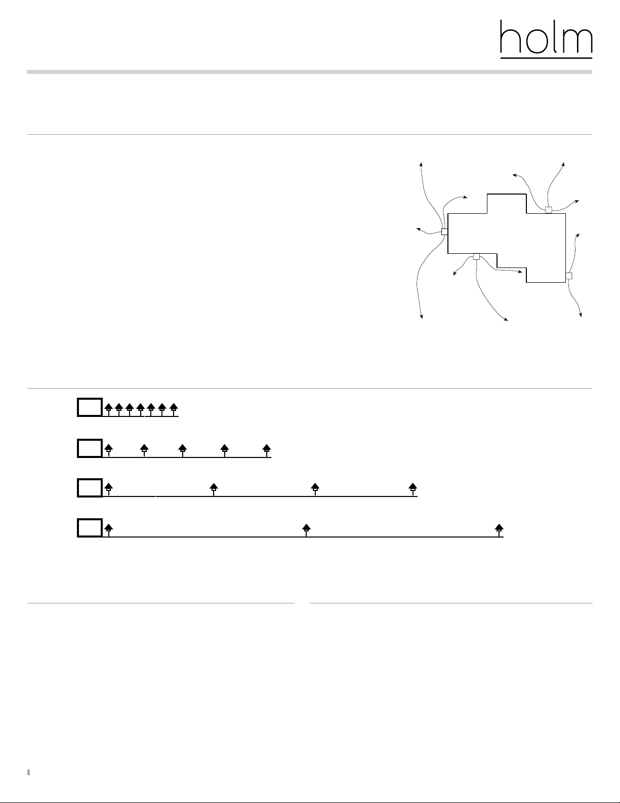
LOW-VOLTAGE CABLE SHALL:
1. Be protected by routing in close proximity to the luminaire or fitting, or next to
a building structure.
2. Not be buried except for a maximum 6 inches (15.2 cm) in order to connect to
the main low voltage cable.
3. Have the length cut off so that it is connected to a connector within 6 inches
(15.2 cm) from a building structure, a luminaire, or fitting.
AVERTISSEMENT – Pour réduire le risque D’INCENDIE OU DE BLESSURE:
■ Éteignez/débranchez la lampe et laissez-la refroidir avant de la remplacer.
■ La lampe devient rapidement BRÛLANTE. Ne touchez que l’interrupteur/
la prise lors de la mise sous tension.
■ Ne touchez pas la lentille, le dispositif de sécurité ni le boîtier lorsqu’ils
sont chauds.
■ N’approchez pas la lampe de matériaux pouvant s’enflammer.
■ Ne touchez jamais la lampe. Utilisez un chiffon doux.
■ La graisse de la peau peut endommager la lampe.
■ N’utilisez pas le raccord du luminaire si le bouclier est absent ou endommagé.
AVERTISSEMENT – Risque d’électrocution
■ Installez tous les luminaires à 3,05 m (10 pieds) ou plus d’une piscine, d’un
spa ou d’une fontaine.
■ Les luminaires ne doivent pas utiliser de lampes tungstène-halogène à moins
que le luminaire soit prévu pour ce type de lampe.
■ Le raccordement au réseau électrique et les différents matériels électriques
doivent installés au-dessus du niveau du sol, exception faite pour les fils ou
réseaux secondaires qui conviennent aux lieux humides.
LE CÂBLE BASSE TENSION DEVRA:
1. Être protégé en le faisant passer à proximité du luminaire ou du raccord,
ou à côté d’une construction comme une maison ou une terrasse.
2. Ne pas être enterré sauf à un maximum de 15,2 cm (6 pouces) pour être
branché au câble basse tension principal.
3. Être raccourci de manière à être branché à un connecteur situé à moins de
15,2 cm (6 pouces) d’une construction, d’un luminaire ou d’un raccord.
Save These Instructions: Conservez Soigneusement Ces Instructions:
DO NOT EXCEED 15 VOLTS IN THIS FIXTURE
The LEDs in this product function ideally when the incoming voltage is between
10–15 volts. Voltages outside of this range may damage the LEDs, shorten their
life, and cause unsatisfactory performance. The use of improper voltage voids
the product warranty. Use only a UL 1838 approved power supply.
RISK OF FIRE WARNING: DO NOT USE LOW-VOLTAGE LUMINAIRES WITH
ANY STYLE OF TRANSFORMER THAT EXCEEDS 15 VOLTS ON THE SECONDARY.
These installation guidelines are to assist you in correctly installing luminaires and transformers. For any questions, call Holm Technical Support
at 877-848-9329 before proceeding. Follow all NEC guidelines and local electrical codes. For more information, visit: holmlighting.com
Recessed
4" (10 cm)
down light
housing
Connector
rPollux-13
luminaire
FIGURE B
Ceiling
Ceiling
Low-Voltage
Landscape Lighting
3YJ8
INSTALLATION NOTES: Low-Voltage System Layout
HL-015 3/18
Learn more about Holm products. Visit holmlighting.com or call the Holm Lighting Technical Support Line at 877-848-9329
Circuiting Guidelines:
Loads Per Cable
Add cable runs as necessary
T
T
Close-Zone 0–40' using voltage tap 12
Mid-Zone 40–80' using voltage tap 12
Far-Zone 80–120' using voltage tap 13
Out There-Zone 120–160' using voltage tap 14
T
12 180 watts max. 10 300 watts max.
12 95 watts max. 10 150 watts max.
12 100 watts max. 10 160 watts max.
12 110 watts max. 10 175 watts max.
T
These installation guidelines are to assist you in correctly installing luminaires and transformers. For any questions, call Holm Technical Support
at 877-848-9329 before proceeding. Follow all NEC guidelines and local electrical codes. For more information, visit: holmlighting.com
T
T
T
T
Single Transformer
When using only one transformer, it is very important to center the transformer on the wattage
load. If the project calls for 135 watts in both front and back areas, the transformer should be
centered on the side of the project that will receive the most lighting. A common mistake is to
locate the single transformer on the service side or in the utility closet, which might result in
excessively long cable runs to reach lighted areas. The primary goal in laying out low-voltage
systems is to minimize cable runs because of voltage drop and cost.
Multiple Transformers
A common mistake in laying out multiple transformer circuits is to group several transformers
in one location because of utility or visual considerations only. As with any low-voltage layout,
the prime directive should be to locate the transformers as close to the luminaires as possible in
order to minimize cable runs. The other multi-transformer layout consideration is “use zoning.”
Having several transformers allows the client to selectively control light in separate areas. This
design approach is to individually control areas that have similar needs. In lighting, a recreation
area has different lighting needs than does a front entry. Therefore, the lights that serve these
different lighting use areas need to be on separate transformers and switch controls. Use of
the ZDlink or ZDCLink transformer oers the alternative solution, allowing zoning and dimming
capabilities on a single transformer. Sample diagram with transformer placement
Transformers:
■For maximum light output, tune lighting circuits to provide
between 10 and 15 volts as measured at the luminaire when
all of the loads on the circuit are operating.
■Voltage can be regulated by adjusting circuit load/run.
■To determine circuit voltage, use a digital voltmeter.
■Connectors used to connect a luminaire or output circuit component
to the main low-voltage cable shall be copper or copper alloy, or the
equivalent.
■When installed, the connection shall guard against inadvertent shorting
of current-carrying parts.
■Wire nuts are not to be used unless provided with corrosion protection,
intended for outdoor use, and designed for direct burial.
LED Life: Connectors:

Other Holm Landscape Lighting manuals

Holm dCrest-9 Quick start guide

Holm

Holm dCrest-9 Quick start guide

Holm rNook-16 Quick start guide

Holm

Holm rNook-16 Quick start guide

Holm dCrest-13 Quick start guide

Holm

Holm dCrest-13 Quick start guide

Popular Landscape Lighting manuals by other brands

Malibu Boats LZ4HW instructions

Malibu Boats

Malibu Boats LZ4HW instructions

TIME LED IP65 GU10 Installation and operating instructions

TIME LED

TIME LED IP65 GU10 Installation and operating instructions

Volt VPL-1042-4-BBZ installation instructions

Volt

Volt VPL-1042-4-BBZ installation instructions

IKEA SOLVINDEN manual

IKEA

IKEA SOLVINDEN manual

Lumacell MQM-NC Series installation instructions

Lumacell

Lumacell MQM-NC Series installation instructions

AMP Lighting ONE ControlPro AAL-1813IR-40-BBZ Installation & maintenance guide

AMP Lighting

AMP Lighting ONE ControlPro AAL-1813IR-40-BBZ Installation & maintenance guide

V-TAC VT-820 Installation instruction

V-TAC

V-TAC VT-820 Installation instruction

SLV 229050 instruction manual

SLV

SLV 229050 instruction manual

Conrad 64 90 06 operating instructions

Conrad

Conrad 64 90 06 operating instructions

Thorn AVENUE VIRTUAL installation instructions

Thorn

Thorn AVENUE VIRTUAL installation instructions

StarShower M9433 user manual

StarShower

StarShower M9433 user manual

Oase LunAqua Terra operating instructions

Oase

Oase LunAqua Terra operating instructions

Intex QES1500 owner's manual

Intex

Intex QES1500 owner's manual

Malibu Boats LZ313 instructions

Malibu Boats

Malibu Boats LZ313 instructions

Perel CSOL08 quick start guide

Perel

Perel CSOL08 quick start guide

Cooper Lighting MCGRAW-EDISON 1192 Specification sheet

Cooper Lighting

Cooper Lighting MCGRAW-EDISON 1192 Specification sheet

Intermatic Malibu LZ305PSM instructions

Intermatic

Intermatic Malibu LZ305PSM instructions

Malibu Boats LT8 instructions

Malibu Boats

Malibu Boats LT8 instructions

manuals.online logo
manuals.online logoBrands
  • About & Mission
  • Contact us
  • Privacy Policy
  • Terms and Conditions

Copyright 2025 Manuals.Online. All Rights Reserved.