HOLOPHANE Enduration User manual

HOLOPHANE®
ENDURATRON®Installation and
Maintenance
Manual
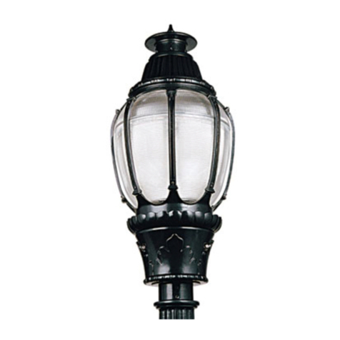
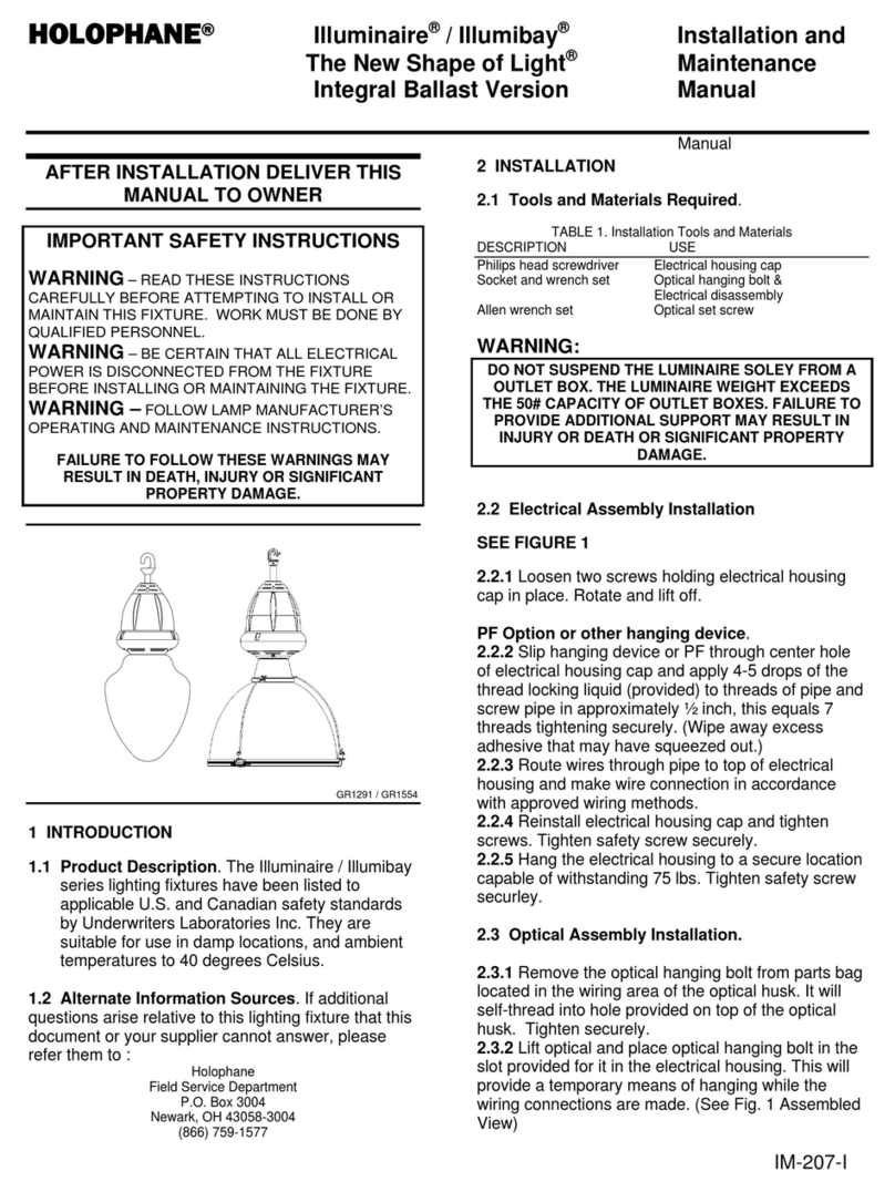
GR1692
GR1791
AFTER INSTALLATION DELIVER THIS
MANUAL TO OWNER
IM-274-E
1
IMPORTANT SAFETY INSTRUCTIONS
WARNING –READ THESE INSTRUCTIONS
CAREFULLY BEFORE ATTEMPTING TO INSTALL OR
MAINTAIN THIS FIXTURE. WORK MUST BE DONE BY
QUALIFIED PERSONNEL.
WARNING – DISCONNECT ALL ELECTRICAL
POWER FROM THE FIXTURE BEFORE INSTALLING OR
MAINTAINING THE FIXTURE.
WARNING – THE INSTALLER MUST FOLLOW LAMP
MANUFACTURER’S OPERATING AND MAINTENANCE
INSTRUCTIONS.
FAILURE TO FOLLOW THESE WARNINGS MAY
RESULT IN DEATH, INJURY OR SIGNIFICANT
PROPERTY DAMAGE.

IM-274-E
2
1 INTRODUCTION
1.1 Product Description.
The Enduratron lighting fixture has been listed to
applicable U.S. and Canadian safety standards
by Underwriters Laboratories Inc.
1.2 Alternate Information Sources:
Holophane
Field Service Department
P.O. Box 3004
Newark, OH 43058-3004
(866) 759-1577
2 INSTALLATION
This fixture should be installed in mounted
accordance with local codes and regulations.
2.1 Tools and Materials Required.
TABLE 1. Installation Tools and Materials
DESCRIPTION use
Flat head screwdriver Open wire way cover
3/8” socket set Electrical component
replacement
2.2 Unit installation
2.2.1 Unit With Hook
•Remove the unit from carton and hang it by its
hook on appropriate loop or eyebolt secured to
building structure. Secure the fixtures to the loop
or eyebolt by tightening screw until screw
touches hook as shown in Figure 1.
Figure 1
SCREW
LOOP OR
EYEBOLT
HOOK
GR1790
•PHCB, Cord and Plug, or Cord Only Unit With
Hook Installation
oIf cord only, attach appropriate connector in
accordance with appropriate local codes and
regulations.
oConnect twist lock plug to outlet device in
vicinity of fixture.
•Holoflex Unit With Hook Installation
oConnect Holoflex plug to Holoflex wiring
system port in vicinity of fixture.
2.2.2 Pendant Mount Installation
•Apply thread locking material to ¾-14 NPT hook
or pipe threads.
•Thread male hook or pipe at least 5 full turns into
housing threaded entry until secure.
WARNING
THE INSTALLER MUST APPLY THREAD
LOCKING MATERIAL TO THE PIPE ENTRY
THREADS BEFORE INSTALLING INTO
HOUSING. FAILURE TO APPLY A THREAD
LOCKING MATERIAL TO THE THREAD CAN
RESULT IN INJURY OR DEATH OR
S
I
G
NIFI
C
ANT PR
O
PERTY DAMA
G
E.
2.2.3 Wiring the unit:
•To open wire way cover, loosen the two screws
holding the cover until it is free to turn.
•Turn the cover counter-clockwise at 90 degrees
see Figure 2.
•Route the supply leads through pipe entry and
through wire way opening and use wire nuts to
connect black to black, white to white and green
to green as shown on Figure 2.
2.2.4 Installing The Lamp Enclosed Unit
•Open enclosed door carefully by releasing the
two clips holding the door shut. Holding the door,
gently let the door swing to a vertical position and
let hang while lamping. Install proper lamp type
and tighten lamp securely into socket.
•Energize the luminaire, lamp should strike within
1-2 minutes.

IM-274-E
3
Figure 2
SUPPLY
CONNECTIONS WIREWAY
COVER
2X SCREWS
GR1792
2.3 Options Installations:
2.3.1 Safety Chain Option Installation:
•Use 3/8 socket driver to drive the screw until it
seats firmly against the washer and chain link
see Figure 3.
•Attach the other end of the chain to an
appropriate support structure leaving no more
than 3 inches of slack.
Figure 3
CHAIN SCREW
WASHER
HOUSING
GR1696
2.3.2 Dimming Option Wiring Connection
•Connect Dimming Leads to the terminal block as
shown in Figure 4.
•Fixtures with ISHB dimming option will be
shipped with sensor rotated close to optic
assembly. Loosen mounting screw and rotate
ISHB dimming assembly as shown in Figure 8.
Re-tighten screw when complete.
Figure 4
VIOLET (+) GRAY (-)
VIOLET (+)
GRAY (-) IN
OUT TO
OTHER FIXTURE
GR1793
2.4 MAINTENANCE
2.4.1 Re-lamping the fixture.
•Power down the luminaire by either turning off
the branch circuit breaker or removing the
luminaire input plug if so equipped.
WARNING
DISCONNECT ALL ELECTRICAL POWER FROM
THE FIXTURE BEFORE MAINTAINING THE
FIXTURE. THE INSTALLER MUST FOLLOW LAMP
MANUFACTURER’S OPERATING AND
MAINTENANCE INSTRUCTIONS. FAILURE TO
FOLLOW THESE WARNINGS MAY RESULT IN
DEATH, INJURY OR SIGNIFICANT PROPERTY
DAMAGE.
WARNING
LEAVE NO MORE THAN THREE INCHES OF
SLACK IN THE CHAIN WHEN ATTACHING TO
THE BUILDING STRUCTURE. LEAVING
ADDITIONAL SLACK WILL ALLOW A LONGER
FREE-FALL, A RESULTING LARGER IMPACT
LOAD, AND POSSIBLE STRUCTURAL
FAILURE. FAILURE TO INSTALL THE CHAIN
AS INSTRUCTED MAY RESULT IN INJURY OR
DEATH OR SIGNIFICANT PROPERTY
DAMAGE
CAUTION
IN ALL DIMMING INSTALLATIONS, IT IS
NECESSARY THAT THE POLARITY OF THE
DIMMING CONTROL LEADS TO THE FIXTURE
BE MAINTAINED. CROSSING OF THE
POLARITY WILL CAUSE IMPROPER AND
UNEXPECTED DIMMING RESULTS AND MAY
LEAD TO DAMAGE TO THE BALLAST
DIMMING CIRCUITS.

IM-274-E
4
•Brush off loose dirt and debris. The optical
assembly may be cleaned with water and
detergent to return it to maximum optical
performance. Dry the assembly with a clean
cloth.
•Check the exterior of the housing for evidence of
damage or potentially hazardous conditions.
•Remove the lamp when cool and replace with the
exact type shown on the luminaire ballast
housing.
•Restore power to the luminaire, the lamp should
strike within 1-2 minutes.
2.4.2 Ballast Replacement
•There are no user serviceable parts or fuses on
the ballast
•Disconnect electrical power to the fixture.
REMOVE THE FIXTURE TO A HORIZONTAL WORK
SURFACE BEFORE ATTEMPTING TO REMOVE ANY
SCREWS THAT SECURE THE HOUSING AND OPTIC
ASSEMBLY TOGETHER. FAILURE TO DO SO MAY
RESULT IN INJURY OR DEATH OR SIGNIFICANT
PROPERTY DAMAGE.
•To separate the electrical assembly from the
optic assembly, use 3/8 socket driver to unscrew
two screws from the electrical housing assembly.
For standard construction see Figure 5.
For EA option construction see Figure 7.
•Carefully disconnect the leads between the optic
assembly and electrical assembly
•Disconnect all leads connected to the ballast
•Loosen four screws holding the ballast to the
housing
•To re-install the ballast to the unit reverse
previous steps and make sure the ballast is
installed tightly to the wall.
2.4.3 Optical Component Replacement
•Disconnect electrical power to the fixture.
REMOVE THE FIXTURE TO A HORIZONTAL WORK
SURFACE BEFORE ATTEMPTING TO REMOVE ANY
SCREWS THAT SECURE THE HOUSING AND OPTIC
ASSEMBLY TOGETHER. FAILURE TO DO SO MAY
RESULT IN INJURY OR DEATH OR SIGNIFICANT
PROPERTY DAMAGE.
•Check, the exterior of the housing, arched rods,
socket, top and bottom rings for evidence of
damaged or potentially hazardous conditions.
•To separate the optic from the electrical
assembly, use 3/8 socket driver to unscrew three
screws from the bottom ring, see Figure 6.
•Remove damaged optic from the assembly.
•Position the replacement optic into bottom ring.
•Set the electrical assembly on the top of the
replacement optic.
•Install three arched rod ends to top ring,
•Install three arched rods to bottom ring.
•Install screws (Apply torque 55-65 inch pound)
onto bottom ring nuts and evenly tighten.
•Install lamp of proper wattage as specified on
luminiare.
3 Operation of the Electronic Ballast
3.1 Luminaire Operation
•Lamp Starting
When the is unit powered, the lamp should strike
within 1-2 minutes.
3.2 Dimming
The Enduratron luminaires can be dimmed to
50% power with the application of a 0-10Vdc
dimming signal applied to the dimming terminals
on the top of the luminaire. If no dimming signal
is connected to the dimming terminals, the
luminaires will operate continuously at 100%
power.
The dimming operation of electronic ballast is
suspended for the first 20 minutes of operation of
the luminaire. The lamp will operate at 100%
power during this period. This delay is required to
stabilize the lamp thermally to permit good color
control and lamp stability thru life as prescribed
by the lamp manufactures.
4 Limited Warranty and Limitation of Liability
The Holophane limited warranty and limitation of
liability published in the Holophane Price
Schedules and is available from your local
Holophane sales representative.

IM-274-E
5
Figure 5 – Standard Construction
2X SCREWS
ELECTRICAL
ASSEMBLY
OPTIC
ASSEMBLY
GR1794
Figure 6
3X SCREWS
(APPLY TORQUE
55-65 IN-IB)
BOTTOM
RING
ELECTRICAL
ASSEMBLY
3X ARCH
ROD
TOP
RING
OPTIC
GR1795
Figure 8 – Indiviual Sensored Highbay Dimming
ISHB DIMMING ORIENTATION
MOUNTING SCREW
GR1937
Figure 7 – EA option Construction
ELECTRICAL
ASSEMBLY
OPTICAL
ASSEMBLY
2X SCREWS
GR1916

IM-274-E
6
Trouble Shooting Guide
Problem Possible Cause Remedy
Lamp does not start
•Lamp has failed at end of life •Replace Lamp
•Lamp is slow starting due to age
•Ballast failure •Wait 1 hour – Replace lamp if it does not start
•Replace ballast
•Ballast staring period has timed out •Recycle power to the luminaire
Lamps cycle on and
off •Energy Management System
programming •Reprogram Energy Management System
•Replace Lamp
•Lamp end of life
Lamp dim •Lamp in process of failing •Replace lamp
Lamp appears black •Lamp end of life •Replace lamp
Lamps do not dim •Dimming control circuit wiring •Check dimming wiring for opens, shorts or proper
polarity
•20 minute dimming circuit is deactivated •Wait for 30 minutes
EM Lamp Stays on •HID Lamp end of life •HID Replace lamp
®
Acuity Lighting Group, Inc.
214 Oakwood Ave., Newark, OH 43055
IM-274-E 11 ©2010 Acuity Lighting Group Inc.
All Rights Reserved
Visit our web site at www.holophane.com
Printed in Mexico
Table of contents
Other HOLOPHANE Light Fixture manuals
Popular Light Fixture manuals by other brands

Wildfire
Wildfire LT-150 series Operation manual

SSS Siedle
SSS Siedle VL 611-X/1-0 Series Product information

ELMEKO
ELMEKO LLX-400-SV Installation and operating manual

Chauvet Professional
Chauvet Professional ROGUE R3 SPOT Quick reference guide

Hayward
Hayward Universal ColorLogic Installation and operation manual

Deco Lighting
Deco Lighting D402-LED installation instructions