HOLOPHANE Phuzion PHZL Manual

LED IMPORTANT SAFETY INSTRUCTIONS
To reduce the risk of death, personal injury or property damage from fire, electric shock, falling parts, cuts/abrasions, and
other hazards please read all warnings and instructions included with and on the fixture box and all fixture labels.
Before installing, servicing, or performing routine maintenance upon this equipment, follow these general precautions.
Installation and service of luminaires should be performed by a qualified licensed electrician.
Maintenance of the luminaires should be performed by person(s) familiar with the luminaires’construction and operation
and any hazards involved. Regular fixture maintenance programs are recommended.
It will occasionally be necessary to clean the outside of the refractor/lens. Frequency of cleaning will depend on ambient
dirt level and minimum light output which is acceptable to user. Refractor/lens should be washed in a solution of warm
water and any mild, non-abrasive household detergent, rinsed with clean water and wiped dry. Should optical assembly
become dirty on the inside, wipe refractor/lens and clean in above manner, replacing damaged gaskets as necessary.
DO NOT INSTALL DAMAGED PRODUCT! This luminaire has been properly packed so that no parts should have been
damaged during transit. Inspect to confirm. Any part damaged or broken during or after assembly should be replaced.
Recycle: For information on how to recycle LED electronic products, please visit www.epa.gov.
These instructions do not purport to cover all details or variations in equipment nor to provide every possible contingency
to meet in connection with installation, operation, or maintenance. Should further information be desired or should
particular problems arise which are not covered sufficiently for the purchaser’s or owner’s purposes, this matter should be
referred to Acuity Brands Lighting, Inc.
READ AND FOLLOW ALL SAFETY INSTRUCTIONS!
SAVE THESE INSTRUCTIONS AND DELIVER TO OWNER AFTER INSTALLATION
Disconnect or turn off power before
installation or servicing.
Verify that supply voltage is correct by
comparing it with the luminaire label
information.
Make all electrical and grounded
connections in accordance with the National
Electrical Code (NEC) and any applicable
local code requirements.
All wiring connections should be capped
with UL approved recognized wire
connectors.
WARNING
RISK OF ELECTRIC SHOCK
Allow lamp/fixture to cool before handling.
Do not touch enclosure or light source.
Follow all manufacturer’s warnings,
recommendations and restrictions for: driver
type, burning position, mounting
locations/methods, replacement and
recycling.
WARNING
RISK OF BURN
Wear gloves and safety glasses at all times
when removing luminaire from carton,
installing, servicing or performing
maintenance.
Avoid direct eye exposure to the light source
while it is on.
CAUTION
RISK OF INJURY
Keep combustible and other materials that
can burn, away from lamp/lens.
Do not operate in close proximity to
persons, combustible materials or
substances affected by heat or drying.
CAUTION
RISK OF FIRE

LED IMPORTANT SAFETY INSTRUCTIONS
Please see product specific installation instructions for additional warnings or any applicable FCC or other regulatory
statements.
Failure to follow any of these instructions could void product warranties. For a complete listing of product Terms and
Conditions, please visit www.acuitybrands.com.
Our Brands Indoor/Outdoor Indoor Lighting Outdoor Lighting Controls
Lithonia Lighting Gotham American Electric Lighting DARK TO LIGHT
Carandini Mark Architectural Lighting Antique Street Lamps Lighting Control & Design
Holophane Peerless Hydrel ROAM
RELOC Renaissance Lighting Tersen Sensor Switch
Winona Lighting Synergy
Acuity Brands Lighting, Inc. assumes no responsibility for claims arising out of improper or careless installation or handling of its products.
ABL LED General Warnings, Form No. 503.203
© 2011 Acuity Brands Lighting, Inc. All rights reserved. 12/01/11
Never connect components under load.
Do not mount or support these fixtures in a manner that can cut the outer jacket or damage wire
insulation.
Unless individual product specifications deem otherwise: Never connect an LED product directly to a
dimmer packs, occupancy sensors, timing devices, or other related control devices. LED fixtures must be
powered directly off a switched circuit.
Unless individual product specifications deem otherwise: Do not restrict fixture ventilation. Allow for
some volume of airspace around fixture. Avoid covering LED fixtures with insulation, foam, or other
material that will prevent convection or conduction cooling.
Unless individual product specifications deem otherwise: Do not exceed fixtures maximum ambient
temperature.
Only use fixture in its intended location.
Electrostatic Discharge (ESD): ESD can damage LED fixtures. Personal grounding equipment must be
worn during all installation or servicing of the unit.
Do not touch individual electrical components as this can cause ESD, shorten lamp life, or alter
performance.
Some components inside the fixture may not be serviceable. In the unlikely event your unit may require
service, stop using the unit immediately and contact an ABL representative for assistance.
Always read the fixtures complete installation instructions prior to installation for any additional fixture
specific warnings.
CAUTION: RISK OF PRODUCT
DAMAGE

HOLOPHANE®PhuzionTM PHZL Remote Installation and
Highbay Luminaire Maintenance
Manual
IM-394
Figure 1
GR2438
1 Introduction
1.1 Product Description. The PhuzionTM PHZL Remote
LED fixtures have been designed and tested in
accordance with applicable UL/CSA standards and are
suitable for use in damp locations. The remote fixture
will come with an Electrical Housing set up for hook
and/or surface mounting. The Optical Housing will be
separate and require a rigid stem attachment. Optical
Housing max weight is 30 lbs. Electrical Housing max
weight is 25 lbs.
2 Installation
2.1 Tools and Materials Required.
TABLE 1
Installation Tools and Materials
DESCRIPTION USE
5/16” socket Electrical Door, Stem Set Screw
3/8” socket Electrical housing surface
mount
2.2 Stem to Optical Housing Installation (Figure 2, 3)
2.2.1 Ensure the ground wire and all (3) sets of input
leads are present and accessible from both ends of the
stem. Do not remove labels from set of red & blue leads.
2.2.2 Remove cover from the wiring chamber of the
Optical Housing (Figure 2). Ensure that the Optical
Housing contains (3) sets of red & blue input wires and a
ground wire.
2.2.3 Route all wires from the stem into Optical Housing
wiring chamber via the ¾” NPT hole and thread the rigid
conduit into place, minimum 6 turns until tight.
2.2.4 Make all wiring connections inside the Optical
housing wiring chamber in accordance with approved
wiring methods.
2.2.5 Reinstall the wiring chamber cover and tighten the
screws
2.2.6 Take care not to pinch any wires while closing the
wiring chamber.
Figure 2
GR2442
Figure 3
GR2439

HOLOPHANE®PhuzionTM PHZL Remote Installation and
Highbay Luminaire Maintenance
Manual
IM-394
2.3 Optical Housing Mounting (Figure 4)
2.3.1 Slide swivel dome and stem cover onto the
mounting stem.
2.3.2 Apply adhesive to threads of the mounting stem
and thread stem fitting into place. Wipe away any excess
adhesive when complete.
2.3.3 Slide stem cover and swivel dome back up the
mounting stem and secure them in place with the
provided swivel dome set screw
2.3.4 Attach hook bracket to an outlet box.
2.3.5 Hang the Optical Housing by placing the stem
fitting onto the hook bracket and install cotter pin.
2.3.6 Route leads from mounting stem into the outlet
box.
2.3.7 Slide cover and swivel dome up stem. Secure
swivel dome with swivel dome set screw to hold cover
against mounting surface. Rigid stem must be mounted
to a suitable structure capable of supporting the full
weight of the Optical Housing in accordance with local
codes.
Figure 4
GR1324
WARNING
FAILURE TO TIGHTEN SET SCREW COULD CAUSE
FIXTURE TO FALL RESULTING IN INJURY, DEATH
OR SERIOUS PROPERTY DAMAGE.
AVERTISSEMENT
NE PAS SERRER CORRECTEMENT LA VIS DE
RÉGLAGE PEUT PROVOQUER LA CHUTE DE LA
FIXATION ET CAUSER DES BLESSURES,
PROVOQUER LA MORT OU DE SÉRIEUX
DOMMAGES MATÉRIELS.

HOLOPHANE®PhuzionTM PHZL Remote Installation and
Highbay Luminaire Maintenance
Manual
IM-394
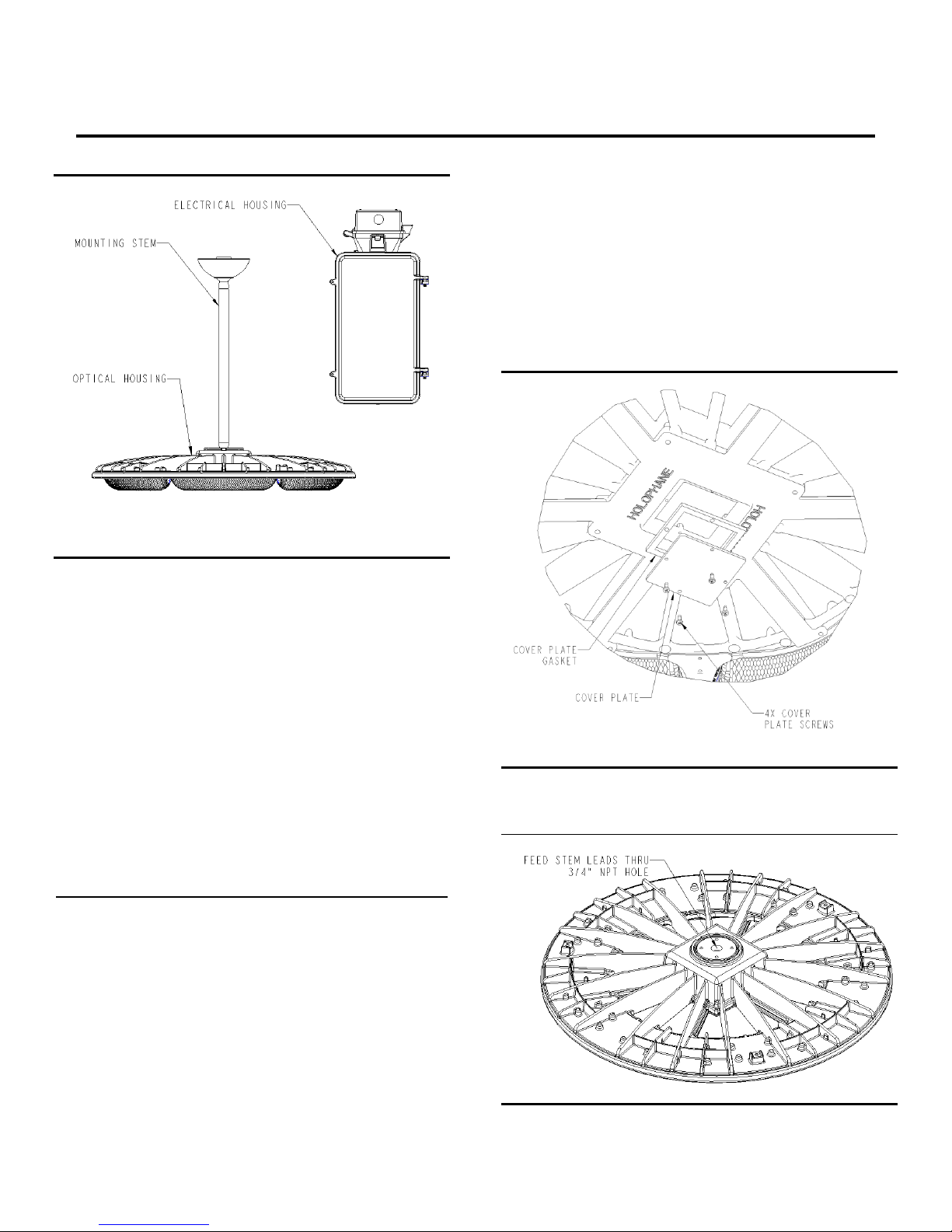
2.4 Electrical Connection of Optical housing to
Electrical Housing (Figure 5, 7)
2.4.1 Determine length of conduit/supply wires needed
to connect the Electrical Housing to the Optical Housing.
Be sure to maintain a minimum length of 5 feet to ensure
required minimum mounting distance between optical
and electrical housings. Maximum lengths are based on
wire gage and can be found on Table 2.
2.4.2 The supply wires should extend 6 inches beyond
the flex conduit for wiring inside the Electrical Housing
junction box and outlet box.
2.4.3 Open the junction box mounted to the top of the
Electrical Housing by loosening the wingnut securing the
two halves of the box together such that the lid can
rotate on its hinge.
2.4.4 Feed connection wires into Electrical Housing
junction box via the knockout holes in the lid
2.4.5 Connect each set of stem conductor leads to a set
of input leads. Be sure to label each set of input leads in
case of future maintenance. Make all wiring connections
in accordance with all local electrical codes.
2.4.6 Attach flex conduit to Electrical Housing junction
box via the ¾” NPT knockouts
2.4.7 Feed wires at the other end of the flex conduit into
customer provided outlet box that the Optical Housing is
mounted to and make all wiring connections in
accordance with all local electrical codes.
2.4.8 Do not pull supply leads beyond 6 inches or
electrical housing wire connections could be pinched or
damaged.
TABLE 2
Maximum Supply Lead Length for Remote PHZL
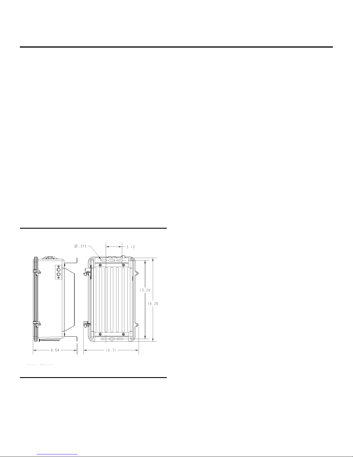
WIRE GAGE
MAX. LENGTH (FEET)
18 AWG
70
16 AWG
120
14 AWG & larger
150
CAUTION
MOUNT ELECTRICAL HOUSING 4 FEET AWAY
HORIZONTALLY FROM THE OPTICAL HOUSING TO
ENSURE ELECTRICAL COMPONENTS DO NOT
EXCEED THEIR MAX TEMPERATURE LIMITS.
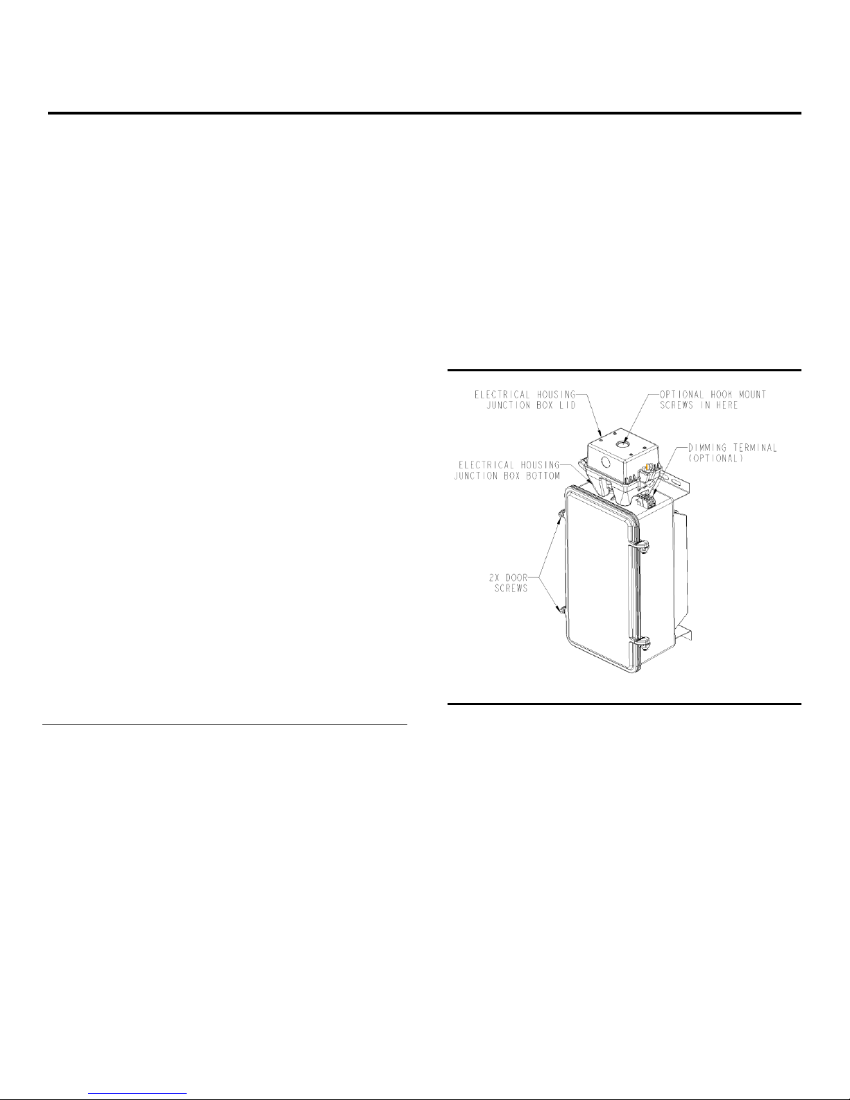
2.5 Electrical Housing Supply Wiring (Figure 5, 7)
2.5.1 Supply wiring connections to the Electrical Housing
are to be made inside the junction box mounted on top
(Figure 5). Supply connection leads should be present
inside the junction box. If supply connection leads are
not present inside the Electrical Housing junction box,
refer to section 3.1 on how to access the Electrical
Housing.
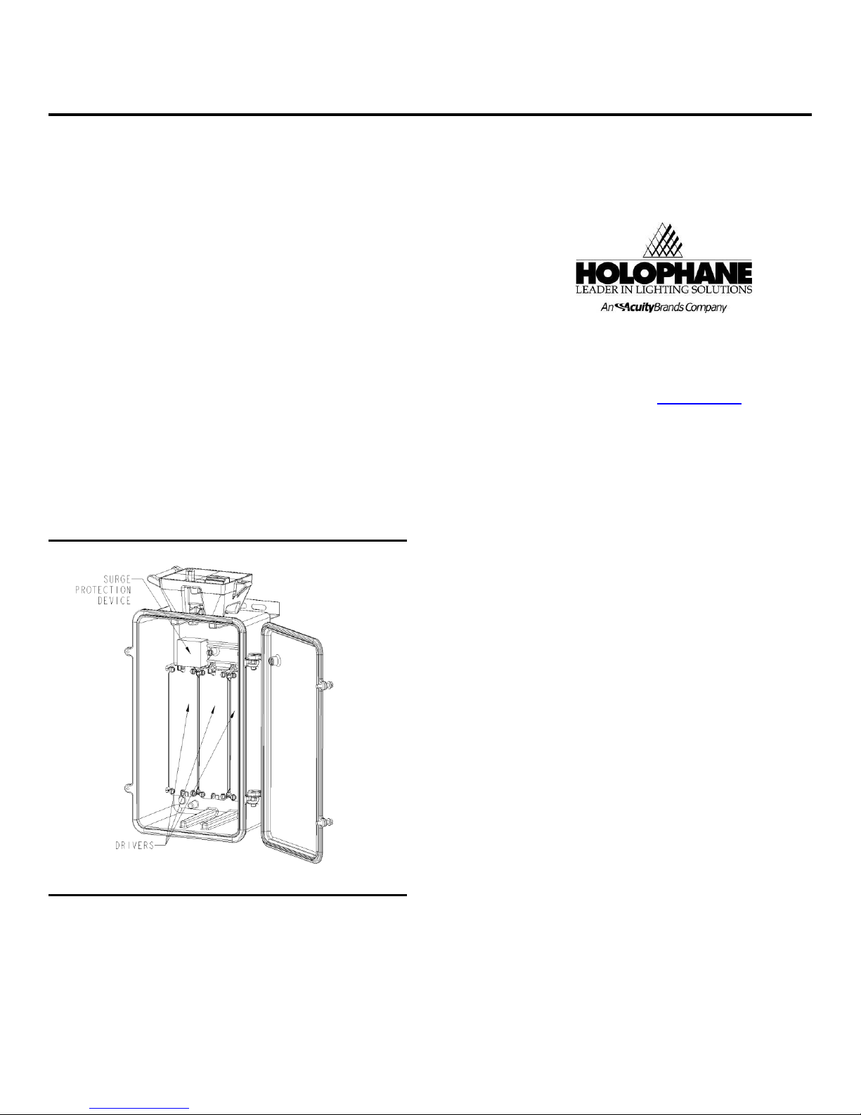
2.5.1.1 After accessing the Electrical Housing,
retrieve supply connection leads and feed them
back through the top of the Electrical Housing
back into the junction box.
2.5.1.2 Close the Electrical Housing. Ensure all
leads are completely inside enclosure and not
pinched.
2.5.2 For supply wiring, make all wiring connections in
accordance with all local electrical codes.
2.5.3 Shut junction box lid and tighten wingnut onto the
supplied J-bolt, ensuring all leads are completely inside
enclosure and not pinched.
Figure 5
GR2440
2.6 Optional 0-10V DC Dimming Wiring (Figure 5)
2.6.1 Optional low voltage dimming terminal is located
on top of the Electrical Housing.
2.6.2 Connect supply dimming leads to the Gray (-) and
Violet (+) DC dimming leads located on the dimming
terminal.
2.7 Flex Conduit to Stem Wiring
2.7.1 For Flex Conduit wiring, remove (1) KO from
junction box (not provided) and insert flex conduit fitting
into KO and secure in place.
2.7.2 Connect green lead to ground lead.
2.7.3 Connect each set of stem conductor leads to a set
of input leads. Be sure to label each set of input leads in
case of future maintenance.
2.7.4 Close junction box and secure Swivel Dome per
section 2.3

HOLOPHANE®PhuzionTM PHZL Remote Installation and
Highbay Luminaire Maintenance
Manual
IM-394
2.8 Electrical Housing - Hook Mounting
2.8.1 Mounting hook (shipped separate from RPHZL
fixture) is installed via the threaded hole at the top of the
Electrical Housing junction box (Figure 5)
2.8.2 Apply sealant evenly to threads of the hook
assembly.
2.8.3 Thread hook tightly into top of Electrical housing
junction box.
2.8.4 Wipe away excess adhesive.
2.8.5 Hang the Electrical Housing on a structure that is
properly sized and attached to support the weight of the
Electrical Housing
2.8.6 Tighten screw in hook to 25-35 ft lbs.
2.8.7 Proceed to section 2.8 for wiring.
2.6 Electrical Housing - Surface Mounting (Figure 6)
2.6.1 Mount Electrical Housing to vertical or horizontal
surface that can support the weight of the Electrical
Housing. If mounted vertically, orient Electrical Housing
with hook on top.
2.6.2 Mounting position locations are show in Figure 6
2.6.3 Mount Electrical Housing using fasteners properly
sized to support the weight of the Electrical Housing
(fasteners not provided).
Figure 6
GR2435
2.10 Safety Chain Option
2.10.1 Safety chain option comes attached to the Optical
housing. Attach loose end to building structure leaving
no more than three inches of slack. Leaving more than
three inches of slack will allow a long free-fall, resulting
in a large impact load and possible structural failure.
WARNING
LEAVE NO MORE THAN THREE INCHES OF SLACK
IN THE CHAIN WHEN ATTACHING TO THE
BUILDING STRUCTURE. LEAVING MORE SLACK
WILL ALLOW A LONGER FREE-FALL, A RESULTING
LARGER IMPACT LOAD AND POSSIBLE
STRUCTURAL FAILURE. FAILURE TO INSTALL THE
CHAIN AS INSTRUCTED MAY RESULT IN INJURY
OR DEATH OR SIGNIFICANT PROPERTY DAMAGE.
AVERTISSEMENT
NE PAS LAISSER PLUS DE TROIS POUCES DE JEU
À LA CHAINE LORS DE LA FIXATION À LA
STRUCTURE DE L'ÉDIFICE. LAISSER PLUS DE JEU
PERMETTRAIT UNE PLUS LONGUE CHUTE LIBRE,
UN IMPACT DE CHARGE PLUS IMPORTANT ET UNE
POSSIBLE DÉFAILLANCE DE LA STRUCTURE. NE
PAS INSTALLER LA CHAÎNE SELON LES
INSTRUCTIONS PEUT PROVOQUER DES
BLESSURES, LA MORT OU DE SÉRIEUX
DOMMAGES MATÉRIELS.

HOLOPHANE®PhuzionTM PHZL Remote Installation and
Highbay Luminaire Maintenance
Manual
IM-394
3.0 Maintenance
3.1 Electrical Component Replacement (Driver,
Surge protector) (Figure 5, 7)
3.1.1 Disconnect power to the luminaire location before
maintenance.
3.1.2Open electrical door by loosening (2) door screws
such that the door can rotate on its hinges. Do not
completely remove the door screws. Do not lift door off
its hinges.
3.1.3 Tag leads before disconnecting if they are not
already labeled.
3.1.4Replace components using Holophane approved
replacement parts.
3.1.5Re-connect electrical leads
3.1.6Shut electrical door and tighten door screws,
ensuring all leads are completely inside enclosure and
not pinched.
3.2 Optical Housing
3.2.1 There are no user serviceable parts in the Optical
Housing.
Figure 7
GR2441
4.0 Limited Warranty and Limitation of Liability
4.1 5-year limited warranty. Complete warranty terms
located at:
www.acuitybrands.com/CustomerResources/Terms_and
_Conditions
Acuity Brands Lighting, Inc.
3825 Columbus Rd., Granville, OH 43023
IM-394 1/18 ©2016 Acuity Brands Lighting, Inc.
All Rights Reserved.
Visit our web site at www.holophane.com
Table of contents
Other HOLOPHANE Light Fixture manuals
Popular Light Fixture manuals by other brands

Beamz
Beamz MADE EAZY BUV LED BAR user manual

Cyclops Lighting
Cyclops Lighting CL280B-E user manual

EuroLite
EuroLite LED SCY-Bar TCL lightset user manual

Triarch
Triarch 32113 installation instructions

Westinghouse
Westinghouse W-029 owner's manual

Larson Electronics
Larson Electronics CL1B-SS-PM-1227 instruction manual