HOLOPHANE Illuminaire User manual

IM-207-I
HOLOPHANE®Illuminaire®/ Illumibay® Installation and
The New Shape of Light®Maintenance
Integral Ballast Version Manual
Manual
AFTER INSTALLATION DELIVER THIS
MANUAL TO OWNER
IMPORTANT SAFETY INSTRUCTIONS
WARNING–READ THESE INSTRUCTIONS
CAREFULLY BEFORE ATTEMPTING TO INSTALL OR
MAINTAIN THIS FIXTURE. WORK MUST BE DONE BY
QUALIFIED PERSONNEL.
WARNING – BE CERTAIN THAT ALL ELECTRICAL
POWER IS DISCONNECTED FROM THE FIXTURE
BEFORE INSTALLING OR MAINTAINING THE FIXTURE.
WARNING – FOLLOW LAMP MANUFACTURER’S
OPERATING AND MAINTENANCE INSTRUCTIONS.
FAILURE TO FOLLOW THESE WARNINGS MAY
RESULT IN DEATH, INJURY OR SIGNIFICANT
PROPERTY DAMAGE.
GR1291 / GR1554
1 INTRODUCTION
1.1 Product Description. The Illuminaire / Illumibay
series lighting fixtures have been listed to
applicable U.S. and Canadian safety standards
by Underwriters Laboratories Inc. They are
suitable for use in damp locations, and ambient
temperatures to 40 degrees Celsius.
1.2 Alternate Information Sources. If additional
questions arise relative to this lighting fixture that this
document or your supplier cannot answer, please
refer them to : Holophane
Field Service Department
P.O. Box 3004
Newark, OH 43058-3004
(866) 759-1577
2 INSTALLATION
2.1 Tools and Materials Required.
TABLE 1. Installation Tools and Materials
DESCRIPTION USE
Philips head screwdriver Electrical housing cap
Socket and wrench set Optical hanging bolt &
Electrical disassembly
Allen wrench set Optical set screw
WARNING:
DO NOT SUSPEND THE LUMINAIRE SOLEY FROM A
OUTLET BOX. THE LUMINAIRE WEIGHT EXCEEDS
THE 50# CAPACITY OF OUTLET BOXES. FAILURE TO
PROVIDE ADDITIONAL SUPPORT MAY RESULT IN
INJURY OR DEATH OR SIGNIFICANT PROPERTY
DAMAGE.
2.2 Electrical Assembly Installation
SEE FIGURE 1
2.2.1 Loosen two screws holding electrical housing
cap in place. Rotate and lift off.
PF Option or other hanging device.
2.2.2 Slip hanging device or PF through center hole
of electrical housing cap and apply 4-5 drops of the
thread locking liquid (provided) to threads of pipe and
screw pipe in approximately ½ inch, this equals 7
threads tightening securely. (Wipe away excess
adhesive that may have squeezed out.)
2.2.3 Route wires through pipe to top of electrical
housing and make wire connection in accordance
with approved wiring methods.
2.2.4 Reinstall electrical housing cap and tighten
screws. Tighten safety screw securely.
2.2.5 Hang the electrical housing to a secure location
capable of withstanding 75 lbs. Tighten safety screw
securley.
2.3 Optical Assembly Installation.
2.3.1 Remove the optical hanging bolt from parts bag
located in the wiring area of the optical husk. It will
self-thread into hole provided on top of the optical
husk. Tighten securely.
2.3.2 Lift optical and place optical hanging bolt in the
slot provided for it in the electrical housing. This will
provide a temporary means of hanging while the
wiring connections are made. (See Fig. 1 Assembled
View)

IM-207-I
Figure 1
GR1334B
2.3.3 Illuminaire or Illumibay Wiring:
2.3.3.1 MH Electro Magnetic, MH Electronic, Inc,
EM & ER: Splice the wires from the optical to
electrical housing as follows: attach black leads to
black leads, white to white and green to green. If the
optical assembly is supplied with the EM or ER
option, splice “INC” to “INC” two places. For Illumibay
ER option, splice Red lead with “INC” on optical end
two places. Other ends will be spliced in conduit box
provided.
MH electronic ballast: Attach White connectors
between optic assembly and electrical housing
assembly, carefully place white connector into optical
husk wiring chamber. See figure. 3 & 4.
Dimming Option Wiring Connection
Dimming voltage operate between 0-10 Volt DC.
Separate dimming leads from main power leads.
Tie dimming leads around the hook assembly with
wire tie. Connect Dimming Leads as shown in
figure 5.
(Polarity is very impotant when connecting
dimming leads)
2.3.3.2 Single Compact Fluorescents: Single lamp
CFL units may be spliced using color coding to
match. Carefully place splices into optical husk wiring
chamber.
2.3.3.3: Multiple Compact Fluorescents: For dual
lamp units, the units need to be spliced following the
diagram provided in Fig. 2. For units with more than
two sockets and the 120W CFL, connect electrical
housing plug to optical receptacle securely. Carefully
push wires up into the electrical housing.
Figure 2
GR1347
2.3.4 Lift optical from this temporary hanging position
and insert into the opening of the electrical housing.
There are protruding lugs that must match up to the
openings in the optical husk.
2.3.5 Carefully line up the lugs with the openings and
push optical into opening. When fully inserted in the
electrical housing, twist clockwise to engage.
2.3.6 Carefully release the optical after insuring that it
has engaged the lugs securely. Tighten set screw
securely to lock the optical from turning or becoming
loose.
2.4 Lamp Installation
2.4.1 Illuminaire
2.4.1.1 Remove relamp door by turning counter-
clockwise. Allow door assembly to hang on cable
provided while lamping. Install proper lamp type (See
relamp information on the optical assembly) and
tighten lamp securely into socket.
2.4.1.2 Install relamp door by pushing relamp cable
up into opening while inserting threaded neck into the
metal receiver in the optical assembly and twist in a
clockwise direction until it seats completely. Do not
over-tighten.
2.4.2 Enclosed Illumibay
2.4.2.1 Open enclosed door by carefully releasing the
two clips holding the door shut. With you holding the
door gently let the door swing to a vertical position
and let hang while lamping. Install proper lamp type
(See relamp information on the optical assembly) and
tighten lamp securely into socket.
WARNING: FAILURE TO TIGHTEN SET SCREW
MAY RESULT IN INJURY OR DEATH OR
SIGNIFCANT PROPERTY DAMAGE.

IM-207-I
2.4.2.2 Close the enclosure door by swinging the
door back to it closed state and fastening the (2) door
clips to ensure a tight fit.
3 MAINTENANCE
3.1 Relamping and cleaning.
3.1.1 Disconnect electrical power to the fixture.
3.1.2 Brush off loose dirt and debris. The optical
assembly may be cleaned with water and detergent
to return it to maximum optical performance. Dry the
assembly with a clean cloth.
3.1.3 Remove the lamp and dispose of it in a safe
and legal manner.
3.1.4 Install the proper lamp type (See the relamp
information on the optical assembly) and tighten the
lamp securely into the socket.
3.1.5 Check the exterior of the housing for evidence
of damage or potentially hazardous conditions.
3.1.6 Connect electrical power to the fixture and
check for proper operation.
3.2 Electrical Component Replacement.
3.2.1 Disconnect electrical power to the fixture.
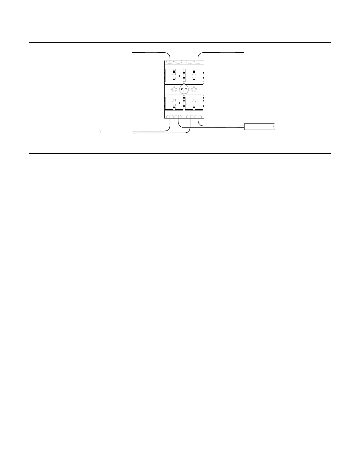
3.2.2 Fuses can be replaced as follows:
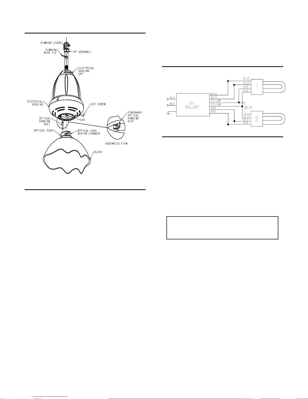
Remove electrical housing cap. (See fig. 1)
Remove fuse holder cap by twisting counter-
clockwise. Replace fuse.
3.2.3 Electrical components located inside the
electrical assembly can be replaced as follows:
REMOVE THE ELECTRICAL HOUSING TO A
HORIZONTAL WORK SURFACE BEFORE ATTEMPTING
TO REMOVE ANY SCREWS THAT SECURE THE
HOUSING HALVES TOGETHER. FAILURE TO DO SO
MAY RESULT IN INJURY OR DEATH OR SIGNIFICANT
PROPERTY DAMAGE.
3.2.4 Remove the optical assembly from the electrical
assembly as follows:
3.2.5 Loosen set screw at the electrical housing
union and carefully twist optical counter-clockwise,
while securely holding, and disengage from electrical
assembly. (Note: Use optical hanging bolt to
temporarily hold the optical while electrical
connections are broken.)
3.2.6 Remove the optical and lay aside in a secure
manner.
3.2.7 Remove the electrical assembly from its
mounting as follows:
3.2.8 Loosen the two screws securing the electrical
housing cap and secure the cap in a manner to allow
easy access to wiring compartment. (A twist-tie can
be used, for example.)
3.2.9 Break all electrical connections.
3.2.10 Remove electrical housing from its hanging
device and place on solid horizontal work surface.
3.2.11 Remove the three screws securing the two
halves of the electrical housing. Keep these screws
for reassembly. Open electrical housing.
3.2.12 Tag electrical wires for identification when
installing the new components, and then break the
electrical connections.
3.2.13 Remove the attaching hardware and retain it
for re-use.
3.2.14 Remove the electrical component and replace
with the new component being careful to not pinch
the electrical wiring.
3.2.15 Install the attaching hardware and tighten the
fasteners securely.
3.2.16 Route and secure all electrical wiring in a
manner similar to its original condition.
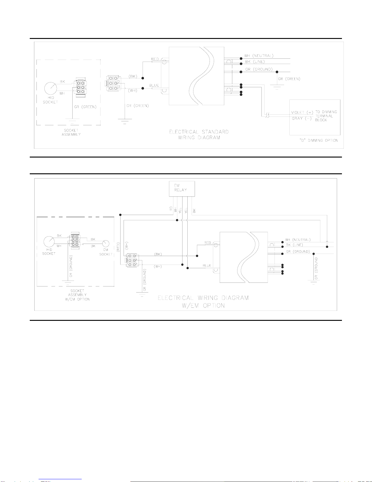
3.2.17 Make electrical connections in accordance
with the wire tags and approved wiring practices.
3.2.18 Check the interior of the housing for evidence
of damage or potentially hazardous conditions.
3.2.19 Reassemble the housing halves together
using the original screws and tighten securely. Be
certain the screws are fully seated and are not cross-
threaded.
3.2.20 Reinstall the components as described in the
installation instructions, section 2.2.
4 Limited Warranty and Limitation of Liability
The Holophane limited warranty and limitation of liability is
published in the "Terms and Conditions" section of the current
Holophane buyer's guide, and is available from your local
Holophane sales representative.

IM-207-I
Figure 3
GR1771
Figure 4
GR1772

IM-207-I
Figure 5
VIOLET (+) GRAY (-)
VIOLET (+)
GRAY (-) IN
OUT TO
OTHER FIXTURE
VIOLET (+) GRAY (-)
GR1773
®
Acuity Brands Lighting , Inc.
3825 COLUMBUS RD., GRANVILLE, OH 43023
IM-207-I 5/24 ©2010 Acuity Brands Lighting Inc.
Visit our web site at www.holophane.com
Printed in USA
This manual suits for next models
1
Table of contents
Other HOLOPHANE Light Fixture manuals