Holzstar BTS 150 User manual

BTS 150
Operating Instruction
Belt and Disc sander
BTS 150
BTS 250

2BTS-Series | Version 3.06
Imprint
Product identification
Belt and disc sander Item number
BTS 150 5904150
BTS 250 5904250
Manufacturer
Stürmer Maschinen GmbH
Dr.-Robert-Pfleger-Str. 26
D-96103 Hallstadt
Fax: 0049 (0) 951 96555-55
E-Mail: [email protected]
Internet: www.holzstar.de
Indications regarding the operating instructions
Original Instruction
Edition: 04.03.2021
Version: 3.06
Language: English
Author: FL
Indications regarding the copyright
Copyright © 2021 Stürmer Maschinen GmbH, Hallstadt,
Germany.
The contents of these operating instructions is the sole
property of the company Stürmer Maschinen GmbH.
Passing on as well as copying of this document, the use
and distribution of its content are prohibited if not explic-
itly permitted. Contraventions are liable to compensa-
tion.
Subject to technical modifications and error.
Contents
1 Introduction ............................................. 3
1.1 Copyright ............................................................ 3
1.2 Customer service................................................ 3
1.3 Limitation of liability............................................. 3
2 Safety ....................................................... 3
2.1 Symbol explanation ............................................ 3
2.2 Obligations of the operating company ................ 4
2.3 Qualification of personnel ................................... 5
2.4 Personal protective equipment ........................... 5
2.5 Safety signs on the Machine............................... 6
2.6 Regulations for safety and accident prevention.. 6
3 Intended Use ........................................... 6
4 Technical Data ....................................... 7
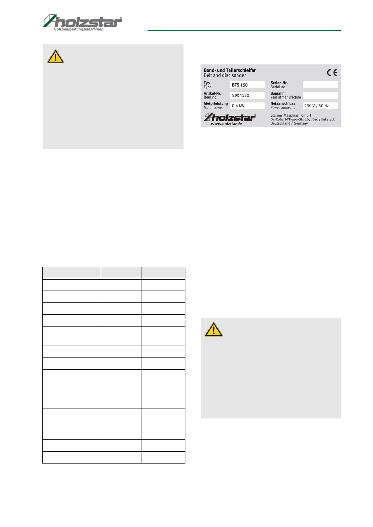
4.1 Type plate........................................................... 7
5 Transport, packaging, storage............... 7
5.1 Delivery and transport......................................... 7
5.2 Packaging ........................................................... 8
5.3 Storage ............................................................... 8
6 Scope of delivery and Accessories ...... 8
6.1 Scope of delivery ................................................ 8
6.2 Accessories ........................................................ 8
7 Description of the device ....................... 9
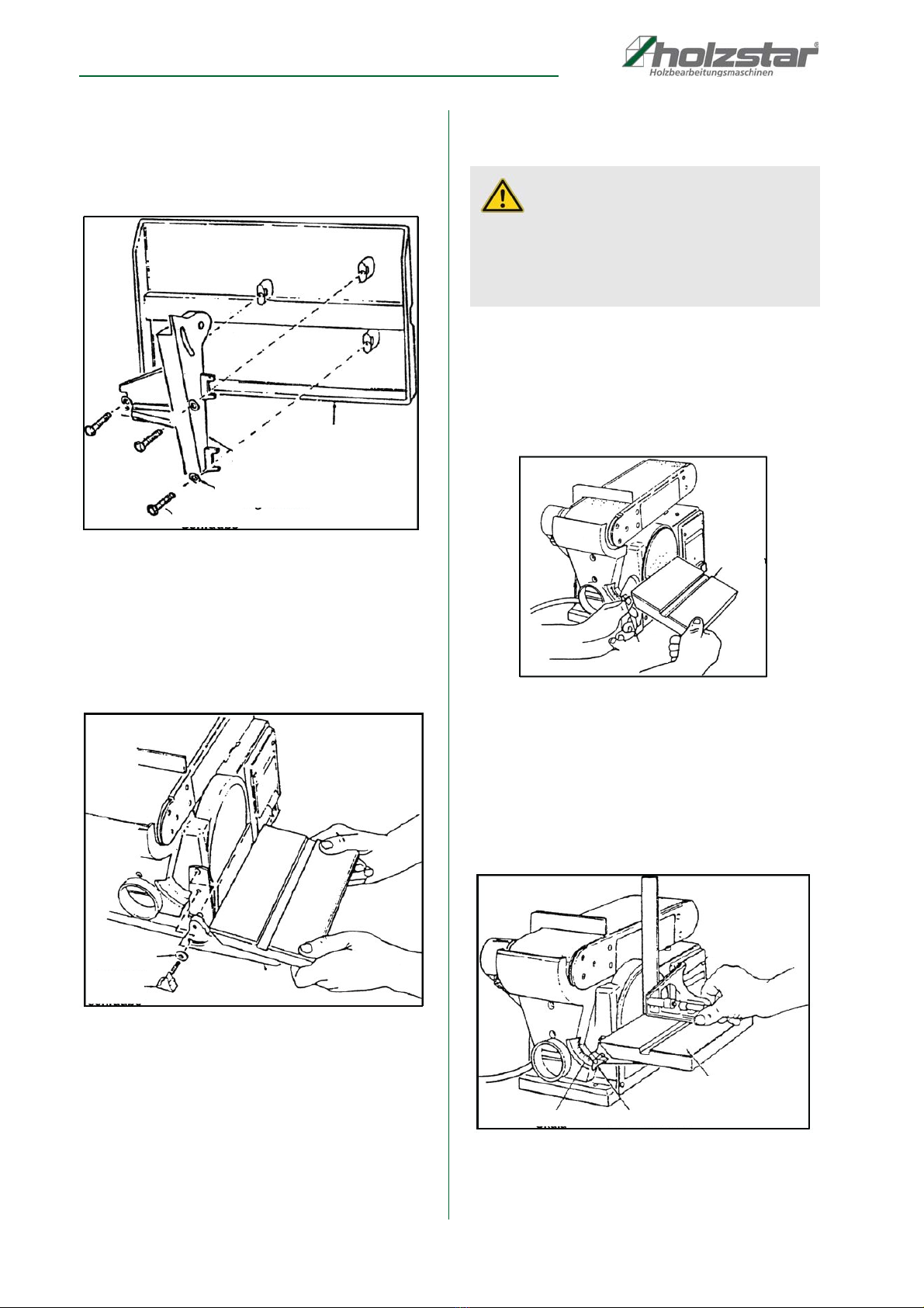
8 Assembly ................................................. 9
8.1 Safety stop.......................................................... 9
8.2 Working table.................................................... 10
9 Settings .................................................. 10
9.1 Pivoting worktable............................................. 10
9.2 Align the working table...................................... 10
9.3 Vertical grinding................................................ 11
9.4 Worktable in vertical grinding position .............. 11
9.5 Grinding wheel change ..................................... 11
9.6 Belt change....................................................... 11
9.7 Sanding belt barrel............................................ 12
10 Operation of the machine................... 12
10.1 Surface grinding on the sanding belt ............. 12
10.2 Edge grinding in vertical grinding position ..... 13
10.3 Grinding bent workpieces .............................. 13
10.4 Grinding round parts on the grinding wheel... 13
10.5 Grinding ends on the grinding wheel ............ 13
10.6 Connecting piece for extraction system......... 14
11 Notes for the grinding process.......... 14
12 Care, maintenance and repair............ 14
12.1 Cleaning......................................................... 14
12.2 Maintenance .................................................. 15
13 Troubleshooting.................................. 16
14 Disposal instructions / recycling
facilities................................................ 16
14.1 Decommission ............................................... 16
14.2 Disposal of new equipment packaging .......... 16
14.3 Disposal of electrical appliances.................... 17
14.4 Disposal of lubricants..................................... 17
14.5 Disposal via municipal collection points......... 17
15 Spare parts .......................................... 17
15.1 Ordering spare parts...................................... 17
16 Spare Parts Drawings ......................... 18
16.1 Spare Parts Drawing BTS 150....................... 18
16.2 Spare parts Drawing BTS 250 ....................... 19
17 EC-Declaration of Conformity............ 20

Introduction
BTS-Series | Version 3.06 3
1 Introduction
You have made a good choice by purchasing the Belt
and disc sander made by HOLZSTAR.
Thoroughly read the operating instructions before
commissioning the machine.
It informs you about the proper commissioning, the in-
tended use as well as the safe and efficient operation
and maintenance of the Belt and disc sander.
The operating instructions are part of the Belt and disc
sander. Always keep it at the place of use of the Belt and
disc sander. Furthermore, the local accident prevention
regulations and the general safety notes are applicable
for the field of application of the Belt and disc sander.
The illustrations in these operating instructions serve the
general comprehension and may deviate from the actual
type.
1.1 Copyright
The contents of these instructions are copyright. Their
application is admissible in the frame of the device. An
application beyond the described application is not allo-
wed without written approval of the manufacturer.For the
protection of our products, we shall register trademark,
patent and design rights, as this is possible in individual
cases. We strongly oppose any infringement of our intel-
lectual property
1.2 Customer service
Please contact your dealer if you have questions on the
machine or if you need technical advice. They will help
you with specialist information and expert advice.
Stürmer Maschinen GmbH
Dr.-Robert-Pfleger-Str. 26
D-96103 Hallstadt
Repair service:
Fax: 0049 (0) 951 96 555 - 55
E-Mail: service@stuermer-maschinen.de
Spare part orders:
Fax: 0049 (0) 951 96555-119
E-Mail: ersatzteile@stuermer-maschinen.de
We are always interested in valuable experience and
knowledge gained from using the application, which then
could be shared and be valuable to develop our products
even further.
1.3 Limitation of liability
All information and notes in these operating instructions
were summarised taking the applicable standards and
rules, the state-of-the-art and our long-term knowledge
and experiences into consideration.
In the following cases the manufacturer is not liable for
damages:
- Non-observance of the operating instructions,
- Inappropriate use
- Use of untrained staff,
- Unauthorised modifications
- Technical changes,
- Use of not allowed spare parts.
The actual scope of delivery may deviate from the expla-
nations and presentations described here in case of spe-
cial models, when using additional ordering options or
due to latest technical modifications.
The obligations agreed in the delivery contract, the gen-
eral terms and conditions as well as the delivery conditi-
ons of the manufacturer and the legal regulations at the
time of the conclusion of the contract are applicable.
2 Safety
This paragraph will give you an overview of all important
safety packages for the protection of the people using it
well as for a safe and undisturbed operation. Other task-
based safety notes are included in the individual chap-
ters
2.1 Symbol explanation
Safety instructions
The safety notes in these operating instructions are high-
lighted by symbols. The safety notes are introduced by
signal words which express the concern of the risk.
DANGER!
This combination of symbol and signal words indi-
cates an imminently dangerous situation which may
lead to death or severe injuries if they are not avoided.
WARNING!
This combination of symbol and signal word indicates
a potentially dangerous situation that can lead to
death or serious injury if not avoided.

4BTS-Series | Version 3.06
Safety
Tips and recommendations
It is necessary to observe the safety notes quoted in
these operating instructions in order to reduce the risks
for personal injuries and damages to property.
2.2 Obligations of the operating com-
pany
The operating company is the person who operates the
machine for business or commercial reasons by herself,
or leaves it to a third party for use or application, and who
bears the legal product responsibility for the protection of
the user, the staff or for third parties.
Obligations of the operating company:
If the machine is used for commercial purposes, the op-
erating company must comply with the legal working
safety regulations. Therefore, the safety notes in this op-
erating manual, as well as the safety, accident preven-
tion and environment protection regulations applying for
the area of application of the machine must be met. The
following applies in particular:
- The operating company must be informed about
the applying industrial safety regulations and fur-
ther analyse hazards resulting from the special
working conditions at the place of use machine.
She must implement these in form of operating
manuals for the operation machine.
- During the entire lifetime of machine, the operating
company must verify whether the operating manu-
als prepared by her correspond to the current sta-
tus of the regulations, and must adapt these if nec-
essary.
- The operating company must unambiguously regu-
late and determine the responsibilities for installa-
tion, operation, troubleshooting, maintenance and
cleaning.
- The operating company must ensure that all per-
sons who work with machine, have read and un-
derstood this manual. Furthermore she must in-
struct the staff in regular intervals and inform them
about the hazards.
- The operator must provide the necessary protec-
tive equipment to the staff and order the use of the
necessary protective equipment in a binding way.
Furthermore the operating company is responsible to
keep the Machine always in a technically flawless state.
Thus, the following applies:
- The operator must ensure that the maintenance in-
tervals described in this manual are kept.
- The operator must have all safety devices checked
regularly for their good working order and their in-
tegrity.
CAUTION!
This combination of symbol and signal word indicates
a potentially dangerous situation that can result in
minor injury if it is not avoided.
ATTENTION!
This combination of symbol and signal words indi-
cates a possibly dangerous situation which may lead
to property and environmental damages if they are
not avoided.
NOTE!
This combination of symbol and signal words indi-
cates a possibly dangerous situation which may lead
to property and environmental damages if they are
not avoided.
Tips and recommendations
This symbol highlights useful tips and recommenda-
tions as well as information for an efficient and trou-
ble-free operation.

Safety
BTS-Series | Version 3.06 5
2.3 Qualification of personnel
The different tasks described in this manual represent
different requirements to the qualification of the persons
entrusted with these tasks.
Only persons reliable working procedures can be ex-
pected from, are allowed to perform all works. Persons
the responsiveness of which is affected by e. g. drugs,
alcohol or medication, are not allowed to work with the
machine.
The qualifications of the personnel for the different tasks
are mentioned below:
Operator:
The operator is instructed by the operating company
about the assigned tasks and possible risks in case of
improper behaviour. Any tasks which need to be perfor-
med beyond the operation in the standard mode must
only be performed by the operator if it is indicated in
these instructions and if the operating company expres-
sively commissioned the operator.
Electrical specialist:
Due to his professional training, knowledge and experi-
ence as well as his knowledge of respective standards
and regulations the electrical specialist is able to perform
works on the electrical system and to recognise and
avoid any possible dangers himself.
Specialist staff:
Due to their professional training, knowledge and experi-
ence as well as their knowledge of relevant regulations
the specialist staff is able to perform the assigned tasks
and to recognise and avoid any possible dangers them-
selves.
Manufacturer:
Certain works may only be performed by specialist per-
sonnel of the manufacturer. Other personnel is not au-
thorized to perform these works. Please contact our cus-
tomer service for the execution of all arising work..
2.4 Personal protective equipment
The personal protective equipment serves to protect per-
sons against impairments of safety and health while wor-
king. The staff has to wear personal protective equip-
ment while performing different works on and with grind-
ing system which are indicated in the individual paragra-
phs of these instructions.
The personal protective equipment is explained in the
following paragraph:
WARNING!
Danger in case of insufficient quali-
fication of the staff!!
Insufficiently qualified persons cannot estimate the
risks while using machine and expose themselves
and others to the danger of severe injuries.
- Have all works only performed by qualified persons.
- Keep insufficiently qualified persons and children
out of the working area.
Ear and head protection
The hearing protection protects the ears against
damages of hearing due to noise. The industrial hel-
met protects the head against falling objects and
bumping into fixed objects.
Eye protection
The protective goggles protect the eyes against parts
flying off and splashes of liquids.
Breathing protection
The breathing protection serves for protecting the
respiratory passages and the lung against the intake
of dust particles.
Protective gloves
The protective gloves serve to protect the hands
against sharp components as well as against friction,
abrasions or deep injuries.
Safety boots
The safety boots protect the feet against crushes, fal-
ling parts and slipping over on slippery underground.
Protective clothes
The protective clothes are tight clothes of little tensile
strength.

6BTS-Series | Version 3.06
Intended Use
2.5 Safety signs on the Machine
The following safety signs and notes are applied on the
grinding system (fig. 1), which need to be observed and
followed..
Fig. 1: Safety labels
Damaged or missing safety symbols at the machine may
lead to errors with personal and material damages. The
safety symbols which are applied on the machine must
not be removed. Damaged safety symbols must be re-
placed immediately.The machine must be put out of ope-
ration from the moment when the labels are unable to be
recognized and understood at first glance, until new la-
bels are attached.
2.6 Regulations for safety and accident
prevention
The following instructions are to be followed by the ope-
rating personnel.
- The noise level (sound pressure level) of this ma-
chine may exceed 82 dB (A) at the workplace. In
this case, sound and hearing protection measures
are required and used by the operator.
- Before operating the machine, read the operating
instructions.
- Never touch rotating or moving parts.
- Always report electrical faults to an electrician.
- Always keep work clothes, long hair, jewelery etc.
away from the machine.
- Switch off machine when work is interrupted.
- Wear suitable safety clothing (accident prevention
shoes, safety glasses, etc.).
- Check safety devices for correct function before
starting work.
- Read and understand safety instructions attached
to the machine.
- Perform regular maintenance.
- Do not overload the machine.
- If the machine is not operating normally, the super-
visor must be informed immediately.
- Caution is advised when people are in the work
area.
- Never change the electrical system.
- Never remove mechanical or electrical safety de-
vices.
- Special attention is needed during transport or re-
construction; The transport regulations must be
followed.
3 Intended Use
The belt and disc sander is used exclusively for sanding
wood and wood-like materials (wood fiber board, chip-
board, plywood boards, laminated and non-laminated
boards, etc.). Grinding other materials can result in fire,
injury or damage. Please pay attention to the instructions
in the operating instructions as well as the information si-
gns on the machine. It must be connected to a suitable
extraction system. The belt and disc sanding machine is
suitable for private use, in schools, craft workshops,
workshops and for home improvement, suitable, not for
industrial use. Proper use also includes compliance with
all information in this manual. Any use beyond the inten-
ded use or otherwise is considered misuse.
Ear protection
Please wear ear protection when working with the
device.
23
4
1

Technical Data
BTS-Series | Version 3.06 7
Unauthorized modifications or changes to the belt and
spindle grinder may void the CE conformity of the Ma-
chine and are prohibited.
The company Stürmer Maschinen GmbH assumes no
liability for design and technical changes to the belt and
spindle grinder.
The improper use of the belt and spindle grinder as well
as the disregard of the safety regulations or the opera-
ting instructions exclude a liability of the manufacturer for
resulting damage to persons or objects and will invali-
date the guarantee!
4 Technical Data
4.1 Type plate
Fig. 2: Type plate BTS 150
5 Transport, packaging, storage
5.1 Delivery and transport
Delivery
Check the Belt & disc sander machine for visible trans-
port damage after delivery. If you discover any damage
to the Belt & disc sander machine, immediately report it
to the carrier or dealer.
Transport
Improper transport is accident-prone and can cause da-
mage or malfunctions for which we do not grant any liabi-
lity or guarantee.
Transport the scope of delivery secured against shifting
or tilting with a sufficiently dimensioned industrial truck to
the installation site.
WARNING!
Risk of misuse!
Misuse of the belt and disc sander can lead to dange-
rous situations.
- Operate the belt and disc sander only in the power
range specified in the technical data.
- Never bypass or override the safety devices.
- Never work on other materials than specified in the
intended use.
- Only operate the belt and spindle grinder in a techni-
cally perfect condition.
- Never work on several workpieces at the same time.
Type BTS 150 BTS 250
Current draw 400 W 800 W
Power output 250 W 560 W
Current consumption 2,0 A 3,8 A
Sanding belt size 915 x 100 mm 1220 x 150 mm
Speed of sanding
belt
490 U/min 517 U/min
Suction Ø 58 mm 120 mm
Sanding pad Ø 150 mm 250 mm
Dimensions Table 230 x 150
mm
360 x 200 mm
Sanding unit swive-
ling
0 - 90° 0 - 90°
Table tilting 0 - 45° 0 - 45°
Dimensions 560 x 270 x
300 mm
720 x 410 x
440 mm
Weight 17 kg 47 kg
Item number 5904150 5904250
WARNING!
Severe or fatal injuries may occur if parts of the
machine tumble or fall down from the forklift
truck, pallet truck or from the transport vehicle.
Follow the instructions and information on the trans-
port box.
Note the total weight of the machine. The weight of
the machine is indicated in the "Technical data" of the
machine. When the machine is unpacked, the weight
of the machine can also be read on the rating plate.
Only use transport devices and load suspension gear
that can hold the total weight of the machine.

8BTS-Series | Version 3.06
Scope of delivery and Accessories
General risks during internal transport
Devices may only be transported by authorized and qua-
lified persons. Act responsibly during transport and al-
ways consider the consequences. Refrain from daring
and risky actions.
Gradients and descents (e.g. driveways, ramps and the
like) are particularly dangerous. If such passages are
unavoidable, special caution is required.
Before starting the transport check the transport route for
possible danger points, unevenness and disturban-ces
as well as for sufficient strength and load capacity.
Danger points, unevenness and disturbance points must
be inspected before transport. The removal of danger
spots, disturbances and unevenness at the time of trans-
port by other employees leads to considerable dangers.
Careful planning of internal transport is therefore essen-
tial.
5.2 Packaging
All used packaging materials and packaging aids of the
grinding system are recyclable and generally need to be
transported to the material recycling.
Crush the packaging material made of cardboard and
supply it to the waste paper collection.
The films are made of polyethylene (PE) and the uphol-
stery parts are made of polystyrene (PS). These materi-
als have to be delivered to a recycling station of the re-
sponsible dumping company.
5.3 Storage
The belt and disc sander must be thoroughly cleaned be-
fore being stored in a dry, clean and frost-free environ-
ment. Cover the machine with a protective tarpaulin.
6 Scope of delivery and Acces-
sories
6.1 Scope of delivery
Check the machine immediately after delivery for trans-
port damage and shortages. To do this, remove all indi-
vidual parts from the box and compare them with the fol-
lowing list.
- Sanding belt grit 60
- Operating instructions
- Suction nozzle adapter 35 to 120mm
- Grinding wheel grit 80 (glued on)
6.2 Accessories
- Base
Item number: 5914250
- Abrasive sheet Ø250 K150, adhesive-backed
Item number: 5912515
- Abrasive sheet Ø250 K120, adhesive-backed
Artikelnummer: 5912512
- Abrasive sheet Ø250 K100, adhesive-backed
Item number: 5912510
- Abrasive sheet Ø250 K80, adhesive-backed
Item number: 5912508
- Abrasive sheet Ø250 K60, adhesive-backed
Item number: 5912506
- Velcro pad Ø250, self-adhesive
Item number: 5912501
- Sanding belt with paper backing 1219x150 K180
Item number: 5911218
- Sanding belt with paper backing 1219x150 K120
Item number: 5911212
- Sanding belt with paper backing 1219x150 K100
Item number: 5911210
- Abrasive belt with paper backing 1219x150 K80
Item number: 5911208
- Abrasive belt with paper backing 1219x150 K60
Item number: 5911206
- Angle stop
Item number: 5914251
WARNING!
The use of unstable lifting and load suspension
equipment that might break under load can cause
severe injuries or even death. Check that the lifting
and load suspension gear has sufficient load-bea-
ring capacity and that it is in perfect condition.
Observe the accident prevention regulations issued
by your Employers Liability Insurance Association or
other competent supervisory authority, responsible
for your company.
Fasten the loads properly.
WARNING: DANGER OF TIPPING
The device may be lifted unsecured by a maximum
of 2cm.
Employees must be outside the danger zone, the
reach of loads.
Warn employees and, if necessary, advise employ-
ees of the hazard.

Description of the device
BTS-Series | Version 3.06 9
7 Description of the device
Fig. 3: Description
1. Track adjustment screw
2. Sanding belt board
3. Tensioning lever
4. Worktable - retaining hole
5. Mounting hole
6. Sanding unit - locking screw
7. Clamping screw - table swiveling
8. Machine foot
9. Safety stop
10. Grinding belt
11. Mounting hole
12. ON / OFF switch
13. Sanding plate protection
14. Worktable
15. Grinding wheel
16. Sanding pad
8Assembly
Remove the machine from its packaging and remove all
protective films. Make sure that the machine is not set up
or put into operation in a damp or wet environment. The
humidity should not exceed 60% and the measured
room temperature should be between 0 ° C and 40 ° C.
For a safe footing, the machine should be mounted on a
stable base (such as a workbench) using the holes provi-
ded in the machine base.
8.1 Safety stop
Take the safety stop as shown in Fig. 4 and fix it with the
hexagon screw M6 x 1.0-14 and the toothed disc. When
tightening the screw, make sure that you fasten the
safety stop approx. 3 mm above the sanding belt. Do not
overtighten the screw, otherwise it may over-tighten.
Fig. 4: Assembly the safety stop
Screw
Safety
Stop
Lock washer
straddle
wrench

10 BTS-Series | Version 3.06
Settings
8.2 Working table
Take the worktable as shown in Fig. 5 and attach it to the
table support with 3 M6 x 1.0-14 hex bolts and washers.
Fig. 5: Mount the table support
Then hold the preassembled worktable to the grinding
machine as shown in Fig. 6 and fix it with the clamping
screw and a washer. The edge of the table must be posi-
tioned with a maximum distance of 2 mm to avoid pin-
ching workpieces or fingers between the table and the
grinding wheel.
Fig. 6: Mount the work table
9Settings
9.1 Pivoting worktable
Loosen the clamping screw and bring the work table into
the desired position. Then tighten the clamping screw
again.
Fig. 7: Pivoting worktable
9.2 Align the working table
To align the work table exactly at 90 °, make a right angle
and hold it to the table as shown in Fig. 8. Then loosen
the table pivot clamping screw and align the table. Finally
tighten the clamping screw again.
Fig. 8: Align the work table
Table
Screw
Washer
Table support
Screw
Washer
Table
DANGER!
Before any intervention on the machine, it must be
disconnected from the power supply. Handling and
working with the machine is only permitted for per-
sons who are familiar with the handling and opera-
tion of the machine.
Table
Screw
Table
Angle
Scale
Screw

Settings
BTS-Series | Version 3.06 11
9.3 Vertical grinding
To do this, loosen the locking screw with the Allen key.
Bring the sanding unit to the desired position and retigh-
ten the locking screw.
Fig. 9: Vertical grinding
9.4 Worktable in vertical grinding posi-
tion
For grinding on the sanding belt in vertical position the
work table can be mounted on the sanding unit. To do
this, remove the safety stop. Bring the sanding unit into
the vertical position as described. Now mount the
worktable on the fixing holes of the safety stop.
Fig. 10: Vertical grinding position
9.5 Grinding wheel change
Disassemble the work table. Loosen the two screws of
the sanding guard and remove it. Replace the grinding
wheel with a new one and then attach the sanding guard.
Fig. 11: Grinding wheel change
9.6 Belt change
To do this, loosen the tension of the sanding belt over
the tensioning lever. Now carefully pull off the old san-
ding belt. Pull on the new sanding belt and align it. Fi-
nally tighten the sanding belt over the tension lever.
Fig. 12: Belt change
NOTE!
This process can be repeated to align the work table
on the sanding belt device in the vertical position.
Wrench
Screw
Belt
Safety stop
Drilling
Washer
Screw
NOTE!
For easier replacement of the sanding belt, the san-
ding unit can easily be swiveled upwards. To lift and
remove the sanding belt, move it back and forth.
Screw
Sanding pad
Cover / Wheel
Tensioning lever

12 BTS-Series | Version 3.06
Operation of the machine
9.7 Sanding belt barrel
The run of the sanding belt can be changed via the track
adjustment screw. When the sanding belt moves toward
the grinding wheel, turn the adjusting screw clockwise.
When the sanding belt moves away from the sanding
wheel, turn the adjusting screw counterclockwise. Then
move the sanding belt by hand in one direction and
check the barrel. Change the run again if necessary.
Fig. 13: Sanding belt barrel
10 Operation of the machine
Please observe the following working instructions so that
your work has the expected success.
Before each start of work the following tests have to be
carried out:Check all cables and plugs.
- Check if the worktable is tight.
- Note that there are different grits of the sanding
plates for different jobs.
- Before starting the machine, make sure that the
washer and the sanding belt rotate freely and are
not braked or blocked by any workpieces.
- Lubricate regularly according to point main-
tenance.
- Prior to commissioning, the center run of the san-
ding belt must always be checked by manual feed!
ON / OFF Switch
To turn on the machine, press the green switch with the
sign (|) for about one second. To switch off the machine,
press the switch with the symbol (O), as shown in Fig.
14.
Fig. 14: ON / OFF Switch
10.1 Surface grinding on the sanding
belt
Check that the safety stop is correctly installed and tigh-
tened. Gently press the workpiece against the sanding
belt and safety stop as shown in Fig.15 with both hands.
For better material removal, the workpiece can be easily
moved back and forth.
DANGER!
Certain types of wood and wood products produce
harmful dust emissions when processed. Therefore,
only use your machine in a well-ventilated area, use
a suction device and wear respiratory protection.
DANGER!
Rotating parts! Get to work with reason. Pay attention
to what you do. Pay special attention to the rotating
parts. Wear tight-fitting clothing. Make sure that hair
or clothing is not caught by rotating parts! Wear a
hairnet.
When working with the machine no jewelry may be
worn.
DANGER!
Flying chips and parts to be thrown off! Be sure to
wear eye protection! Protect your eyes from flying
chips and other splinters.
Wear safety glasses
Adjustment Screw
Wear a dust mask
DANGER!
Do not work with too much pressure, otherwise
The sanding belt wears too fast. Bring
Do not keep your fingers in contact with the sanding
belt.

Operation of the machine
BTS-Series | Version 3.06 13
Fig. 15: Sand surfaces
10.2 Edge grinding in vertical grinding
position
Bring the sanding unit in a vertical position as described
and mount the working table. Hold the workpiece firmly
with both hands and apply light pressure to the sanding
belt. Move the workpiece slightly back and forth.
Fig. 16: Edge grinding
10.3 Grinding bent workpieces
Hold the workpiece firmly with both hands and proceed
as shown in Fig.17. Grind inner curves only at the front
pulley.
Fig. 17: Grinding bent workpieces
10.4 Grinding round parts on the
grinding wheel
Hold the workpiece firmly with both hands and proceed
as shown in Fig.17.
10.5 Grinding ends on the grinding
wheel
When grinding the ends of a narrow workpiece, it is ea-
sier to use the grinding wheel with the miter fence as
shown in Fig.18. Move the workpiece outward from the
center to the left side of the disc.
Stop
Workpiece
Belt
Table
Workpiece
Grinding
belt
Unit
DANGER!
Always grind round parts only on the left side, down
side of the grinding wheel, otherwise the workpiece
can be thrown away.
DANGER!
Always sand on the left side of the grinding wheel, as
shown. The grinding on the right side of the grinding
wheel can cause the workpiece to be thrown
upwards.
The edge of the worktable must be positioned so that
there is a maximum distance of 2 mm to the grinding
wheel to avoid pinching workpieces or fingers bet-
ween the table and the grinding wheel.
Drive roller
Pulley

14 BTS-Series | Version 3.06
Notes for the grinding process
Fig. 18: Grinding ends
10.6 Connecting piece for extraction
system
On the right side under the worktable there is a connec-
tion piece with 58 mm Ø for BTS 150 and 120 mm Ø for
BTS 250 for connection to an extraction system.
11 Notes for the grinding
process
When grinding, pay attention to the safety instructions
and use the protective devices on the machine as well as
your personal protective equipment (protective goggles,
ear protection, safety shoes, etc.).
Special reference to situations that could cause damage
to persons, the machine and / or the environment or
could lead to financial losses:
- When grinding with the material, do not press too
hard against the sanding pad.
- Make sure that the gap between the work table and
the grinding wheel is not too large. Especially with
thin workpieces there is a risk that the workpiece will
enter the gap!
- Since the machine has no clamping facility, it is im-
portant that your workpiece is resting on the work ta-
ble over the entire surface and can be held fast!
- Make sure the grinding wheel is in good condition
and replace used grinding wheels in good time.
Only with perfect tools you can achieve a good grin-
ding quality!
12 Care, maintenance and repair
Always disconnect the machine from the power supply
before starting any cleaning, maintenance or servicing
work!
12.1 Cleaning
Basically, the machine should be cleaned after each use.
When the machine is off, remove the chips and dust with
a broom or brush.
Maintenance and repair work may only be carried out by
qualified personnel.If the belt and disc sander does not
work properly, contact a dealer or our customer service.
The contact details can be found in chapter 1.2 Custo-
mer Service.All protection and safety equipment must be
reinstalled immediately after completion of repair and
maintenance work
.
workpiece
middle
Mitre fence
DANGER!
Do not remove the chips with bare hands. There is a
risk of cuts due to chips and tools!
NOTE!
Oil, grease and cleaning agents are hazardous to the
environment and must not be dumped into wastewa-
ter or normal household waste. Dispose of these
funds in an environmentally friendly way. The cloths
soaked in oil, grease or detergent are easily flam-
mable. Collect the cleaning rags or cleaning wool in a
suitable, closed container and dispose of them in an
environmentally friendly way - do not throw in house-
hold waste!
NOTE!
- Check the grinding belt or the grinding sleeves regu-
larly for errors. Replace a damaged sanding belt or
sanding sleeve immediately.
- Check the correct setting of the tape guide at regu-
lar intervals. Relax the sanding belt during longer
work breaks. Clean the machine at regular intervals.
- Check the adequate function of the extraction daily.
- Replace damaged safety equipment immediately.
- Connections and repairs of the electrical equipment
may only be carried out by a qualified electrician.

Care, maintenance and repair
BTS-Series | Version 3.06 15
Functional test
The belt and disc sanding machine is delivered ready to
use. Before each use, a functional test should be carried
out. The sanding belt must be tensioned.
Step 1: Manually move the sanding belt, making sure it is
centered on the roller. If necessary, readjust the
sanding belt with the ribbon adjustment screw.
Step 2: Switch on the belt and disk sanding machine for
a short time and check the tape again.
Step 3: Switch off the belt and disk sanding machine
again.
Sanding belt
The abrasive belt is a wearing part, which has to be re-
gularly checked for faults and replaced when worn.
Replace a damaged abrasive belt immediately!
The belt is equipped with an automatic tensioning me-
chanism. This eliminates a regular tensioning of the
tape.
Tape guide
Check the tape guide at regular intervals for the correct
setting. If the belt and disk sanding machine is not used
for a long time, the sanding belt must be relaxed.
Suction
Check the suction daily for its adequate function. If the
extraction system does not work or only to a limited ex-
tent, it must be repaired again. Only then may the belt
and disk grinding machine be put into operation.
Lubricate moving parts
Lubricate the bearing points of the pulleys periodically
with a high-quality oil, but at the latest close to about 10
operating hours. Loosen the grinding tension and put 2
drops of oil in the intended opening (see Fig. 19). Do not
use too much oil, otherwise the V-belt may slip or oil may
get onto the workpiece. Then tension the sanding belt
again and adjust the run.
Fig. 19: Maintenance
12.2 Maintenance
Change the Strap
Disconnect the machine before starting any cleaning, main-
tenance or servicing work Always from the power supply!Re-
move the belt housing cover by loosening the Phillips head
screw. Loosen the three mounting screws, which relaxes the
belt. Put the new belt on and tighten it by inserting a flat-
head screwdriver into the auxiliary hole and pushing the belt
housing upwards. Tighten the fastening screws again.
Fig. 20: Change the strap
Wear safety glasses!
Bearing
Tension
lever
Pulley
Strap
Drilling
Wrench

16 BTS-Series | Version 3.06
Troubleshooting
13 Troubleshooting
14 Disposal instructions / recy-
cling facilities
Dispose of your device in an environmentally friendly, by not
disposing of waste in the environment but professio-nally.
Please take the packaging and later the old appliance
does not just go away, but discard them in accordance
with the relevant of your city / municipality or by the wa-
ste disposal company established guidelines.
14.1 Decommission
Discarded appliances are immediately professionally de-
commission, in order to avoid any later misuse and the
threat to the environment or people.
Step 1: Remove all environmentally hazardous materi-
als from the old device.
Step 2: Remove the machine optionally into manage-
able and actionable assemblies and compo-
nents.
Step 3: Leading the machine components and supplies
the appropriate disposal routes.
14.2 Disposal of new equipment
packaging
All used packaging materials and packaging aids of the
machine are recyclable and must always be recycled.
The packaging wood can be sent for disposal or recy-
cling.
Packaging components made of cardboard can be crus-
hed for waste paper collection.
The foils are made of polyethylene (PE) or the upholstery
parts made of polystyrene (PS). These substances can
be reused after processing if they are passed on to a
recycling center or to the disposal company responsible
for them.
Only pass on the packaging material in such a way that it
can be directly recycled.
Fault Possible causes Disposal
Engine is not running Damaged ON / OFF switch
Damaged ON / OFF switch lead
Relay damaged
Engine defective
Fuses defective
Have the machine checked by an electri-
cian and replace the damaged parts
Machine slows down while
working
It is worked with too much pressure Apply less pressure on the workpiece
Low service life of the abra-
sives
Abrasive (tape or disk) with too fine grain Use a grinding wheel with coarse grain
Grinding angle does not fit Adjusted angles on the work table or on
the stop bracket do not fit
Check angle and adjust if necessary
Bad sanding picture Abrasive with too coarse grain Use finer grained abrasive
Grinding wheel runs opti-
cally out of round
Sanding belt not laid correctly Trace the track of the sanding belt
Grinding wheel runs off the
drive pulleys
Sanding belt not laid correctly Trace the track of the sanding belt
Wood burns during grinding Grinding sleeve or abrasive belt is coated
with lubricant. There is too much pres-
sure on the workpiece
Replace the sanding sleeve or sanding
belt. Reduce the pressure on the work-
piece.

Spare parts
BTS-Series | Version 3.06 17
14.3 Disposal of electrical appliances
Please note that electrical units contain a variety of recy-
clable materials and environmentally harmful compo-
nents.
Please contribute that these components are separated
and disposed of properly. If in doubt, contact your muni-ci-
pal waste.
For preparation for commisioning please contact a com-
pany specialized for disposal.
14.4 Disposal of lubricants
The disposal instructions for the lubricants used are pro-
vided by the lubricant manufacturer. If necessary, ask for
the product-specific data sheets.
14.5 Disposal via municipal collection
points
Disposal of used electrical and electronic equipment
(Applicable in the countries of the European Union and
other European countries with a separate collection sy-
stem for these appliances).
The symbol on the product or its packa-
ging indicates that this product should not
be treated as normal household waste but
must be returned to a collection point for
the recycling of electrical and electronic
equipment.By helping to properly dispose
of this product, you are protecting the environment and
health of others. Environment and health are at risk from
improper disposal. Material recycling helps reduce the
consumption of raw materials. For more information on
recycling this product, contact your local community, mu-
nicipal waste disposal service or the shop where you
purchased the product.
15 Spare parts
15.1 Ordering spare parts
The spare parts may be purchased with the authorised
dealer or directly with the manufacturer. Please find the
corresponding contact data in Chapter 1.2 Customer
service.Indicate the following basic information for spare
part orders:
- Type of device
- Serial number
- Quantity
- Designation
- Required mode of dispatch (mail, freight, sea, air,
express)
- Address of dispatch
Spare part orders which do not include the above indica-
tions may not be taken into consideration. If the indicati-
ons regarding the mode of dispatch are missing, the pro-
duct is dispatched at the discretion of the supplier. Infor-
mation on the device type, item number and year of ma-
nufacture can be found on the nameplate, which is at-ta-
ched to the unit.
Example
The engine for the Belt and disc sander BTS 250 must
be ordered. The engine has the number 47 in the spare
parts drawing 1.By ordering spare parts, send a copy of
the spare parts drawing (1) with the marked part (engine)
and marked positon number (47) to the dealer or spare
parts department and provide the following information:
- Tyoe of device: Belt and disc sander
BTS 250
- Item number: 5904250
- Drawing number: 1
- Position number: 47
NOTE!
Please take care in your interest and in the interest of
the environment that all components of the maschine
are disposed according to the rules.
DANGER!
Please pay attention to an environmentally friendly
disposal of the used lubricants. Observe the disposal
instructions of your municipal disposal companies.
DANGER!
Danger of injury by the use of
wrong spare parts!
Dangers may result for the user and damages as well
as malfunctions may be caused by using wrong or
damaged spare parts.
- Only use original spare parts of the manufacturer or
spare parts admitted by the manufacturer.
- Always contact the manufacturer in case of uncer-
tainties.
Tips and recommendations
Using non-approved spare parts voids the manu-
facturer's warranty.

18 BTS-Series | Version 3.06
Spare Parts Drawings
16 Spare Parts Drawings
The following drawings is intended to help in case of service, to identify necessary spare parts. To order send a copy of
the parts drawing with marked components to your dealer.
16.1 Spare Parts Drawing BTS 150
Fig. 21: Spare parts Drawing BTS 150

Spare Parts Drawings
BTS-Series | Version 3.06 19
16.2 Spare parts Drawing BTS 250
Fig. 22: Spare parts Drawing BTS 250

20 BTS-Series | Version 3.06
EC-Declaration of Conformity
According to Machinery Directive 2006/42/EC Annex II 1.A
Manufacturer / distributor: Stürmer Maschinen GmbH
Dr.-Robert-Pfleger-Str. 26
D-96103 Hallstadt
hereby declares that the following product
Product Group: Holzstar® Woodworking machines
Machine type : Belt and disc sander
Designation of the machine *: BTS 150 Item number *: 5904150
BTS 250 5904250
Serial number*: ___________________
Year of manufacture*: 20____
* please fill in according to the information on the type plate
corresponds to all the relevant provisions of the abovementioned Directive and other Directives applied (below) -
including their amendments current at the time of the declaration.
Relevant EU Directive: : 2014/30/EU EMC-Directive
The following harmonized standards were applied:
DIN EN 60204-1:2019-06 Safety of machinery - Electrical equipment of machines - Part 1:
General requirements
DIN ISO 12100 -1:2011-03 Safety of machinery. General principles for design Risk assessment and
risk reduktion (ISO 12100:2010
Responsible for documentation: Kilian Stürmer, Dr.-Robert-Pfleger-Str. 26, D-96103 Hallstadt
Hallstadt, 04.03.2021
______________________
Kilian Stürmer
Manager
17 EC-Declaration of Conformity
This manual suits for next models
3
Table of contents
Other Holzstar Sander manuals