Holzstar KSO 790 User manual

BELT SANDER
MODEL KSO 790 KSO 790
OWNER’S MANUAL
PLEASE SAVE THIS MANUAL FOR FUTURE REFERENCE

GENERAL SAFETY RULES FOR POWER TOOLS
1. KNOW YOUR TOOL Read carefully and thoroughly and understand owner’s operating
manual and labels affixed to the tool. Learn its application and limitations as well as
specific potential hazards peculiar to this tool.
2. KEEP GUARDS IN PLACE In working order, and in proper adjustment and alignment.
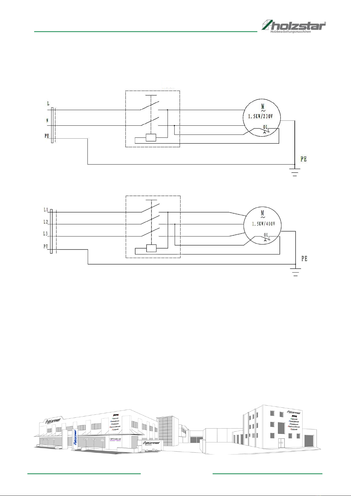
3. GROUND THE TOOL The tool is equipped with a 3 wire lead, it should always be
plugged into a 3-hole electrical receptacle. Never connect the third (green/yellow or
green) wire to a live terminal.
4. REMOVE ADJUSTING KEYS AND WRENCHES Check to see that keys and adjusting
wrenches are removed from tool before turning them on.
5. KEEP WORK AREA CLEAN Cluttered areas and benches invite accidents. Floor must
not be slipped due to wet or sawdust.
6. AVOID DANGEROUS ENVIRONMENT Do not use power tools in damp or wet locations
or expose them to rain. Keep work areas well lighted. Provide adequate surrounding
work space.
7. KEEP CHILDREN AWAY All visitors should be kept a safe distance from work area.
8. MAKE WORKSHOP CHILD-PROOF With padlocks, master switches, or by removing
starter keys.
9. USE PROPER SPEED This tool will do the job better and safer when operated at the
proper speed.
10. USE RIGHT TOOL Do not force tools or attachment to do a job for which it was not
designed.
11. WEAR PROPER APPAREL Do not wear loose clothing, gloves, neckties or jewelry
(rings, wristwatches) to get caught in moving parts. Non-slip footwear is recommended.
Wear protective hair covering to contain long hair. Roll long sleeves above the elbow.
12. USE SAFETY GOGGLES (HEAD PROTECTION) Wear safety goggles at all times.
Everyday eyeglasses only have impact resistant lenses, they are NOT safety glasses.
Also, use face or dust mask if cutting operation is dusty, and ear protectors (plugs or
muffs) during extended periods or operation.
13. SECURE WORK PROPERLY Use clamps or vise to hold work, when practical. It is
safer than using your hands and it frees both hands to operate tool.
14. DO NOT OVERREACH Keep proper footing and balance at all time.
15. MAINTANIN TOOLS WITH CARE Keep tools sharp and clean for best and safest
performance. Follow instructions for lubricating and changing accessories.
16. DISCONNECT TOOLS Before servicing, when changing accessories or attachments,
disconnect from electricity.
17. USE RECOMMENDED ACCESSORIES Consult the owner’s manual for recommended
accessories. Follow the instructions that accompany the accessories. The use of
improper accessories may cause hazards.
18. AVOID ACCIDENTAL STARTING Make sure switches is in “OFF” position before plug
in.
19. NEVER STAND ON TOOL Serious injury could occur if the tool tips over. Do not store
materials such that it is necessary to stand on the tool to reach them.
20. CHECK DAMAGED PARTS Before further use of the tool, a guard or other part that is
damaged should be carefully checked to ensure that it will operate properly and perform
its intended function. Check for alignment of moving parts, binding or moving parts,
breakage of parts mounting, and any other conditions that may affect its operation. A

guard or other part that is damaged should be properly repaired or replaced.
21. NEVER LEAVE MACHINE RUNNING UNATTENTED Turn power “OFF”. Do not leave
the tool until it comes to a complete stop.
22. DIRECTION OF FEED Always feed the workpiece into the blade against the rotation of
blade or cutters.
23. DRUGS, ALCOHOL AND MEDICATION Never operate tools while under influence of
drugs, alcohol, or after taking medication.
WARNING: For Your Own Safety Read Instruction Manual Before Operating Tool. Wear
Eye Protection. Feed workpiece against rotation of sanding belt. Do not use awkward
hand position. Keep fingers away from revolving sanding belt. Use fixtures when
necessary.
SPECIFICATION:
Belt size………………………………………………………2000mm x 152mm(79” x 6”)
Belt speed………………………………………………………………11M/sec. (34ft/sec.)
Motor speed……………………………………………………………………..…2900RPM
Maximum sanding length……………………………………………..……...790mm(31”)
Round end roller diameter……………………………….…………………70mm(2 3/4”)
Table size: Front table…………… ……………….…790mm x 221mm(31” x 8-3/4”)
Side table ………………………………..514mm x 221mm(20” x 8-3/4”)
Vertical adjusting of front table……………………………..……………….110mm(4”)
Table tilt……………………………………………………………………………45 degree
Table height…………………………………………………..….…………….810mm(32”)
Dust chute diameter..………………………………………………………….100mm(4”)
Stand height……………………………………………………………..…..….600mm(23”)
Net weight…………………………………………………………………….78kgs(172lbs)
Gross weight…………………………………………………………………..90kgs(198lbs)
Packing size(carton)……………………………104cm x 54cm x 41cm(41” x21’ x16”)
The specifications dimensions are not binding. Our firm reserves the right to make
changes for improvement and technical reasons.
ASSEMBLY
Due to packaging requirements, your belt sander is partly assembled. Please do not
operate this belt sander before it is completely assembled and all bolts are completely
secured. The number shown in bracket is the part number.
Please refer to the assembly diagram A (or B if needed) to assembly the belt sander. The
following are the steps to complete the assembly of the belt sander.
Step 1: Assemble the stand. Please note that the short bars(#95) are always ride on the
long bars(96#) and the bolt holes are always aligned.
Step 2: Put the main assembly on the stand and fix it on the stand with 4 bolts(#92) and 4
screws(93).
Step 3: Attach the long (front) table to the Main assembly. Insert the U-bar(#85) into the
two slot on the supporting frame of the table. Then insert the U-bar with the table into the
slots on the main assembly. Both end of the U-bar must be penetrated through the two
holes behind the main assembly. Insert a pin(#84) into the pin hole at each end of the
U-bar.
Step 4: Attach the short(side) table to the Main assembly with the four bolts(#7) and four

screws(#62). Then attach the pointer(#66). The degree label is properly turned in factory,
when the table is at its level position, the pointer must be pointing at 90 degree. If not,
please loose the four bolts(#7) and adjust it.
CHANGING SANDING BELT
To change sanding belt, open the cover (#58),then pull off the bar(#35), loosen the
bolt(#45) that on the dust hood(#44). Turn the tension handle to left(anticlockwise). Take
out the sanding belt and replace with a new one. Recover all steps previously done.
Because the size of a new sanding belt is slightly different from the old one, it may affect
the alignment.
Proper tracking is achieved when drive roller and idler roller are aligned to fit the sander
belt. The knob (#14) is used to tilt the idler roller.
POWER CONNECTIONS
ALLL POWER CONNECTIONS MUST BE DONE BY QUALIFIED EELCTRICIAN. A separate
electrical circuit should be used for the sander. This circuit should not be less that No.12
wire and should be protected with a 15 amperes time lag fuse if three phase current is
applied or a 20 Amperes time lag fuse if single phase current is applied. Before
connecting the motor to the power line, be sure that the electric current is of the same
characteristics as stamped on motor nameplate. All line connections should make good
contact.
If extension cord is allowed according to local codes and ordinances. USE PROPER
EXTENSION CORD. Make sure your extension cord is in good condition. When using an
extension cord, be sure to use heavy enough to carry the current your product will draw.
An undersized cord will cause a drop in line voltage resulting in loss of power and
overheating. The correct cord size to be used depends on cord length and nameplate
ampere rating. If in doubt, consult qualified electric service personnel.
NOTE: RUNNING ON LOWER VOLTAGE OR HIGHER VOLTAGE THAN THE VOLTAGE
THAT THE MOTOR WAS DESIGNED WILL DAMADE THE MOTOR.
DUST COLLECTION
For health and safety reason, using a dust collection system while working with this belt
sander is recommended.


No.
Description
No.
Description
1
Sticking Graphite Plate
55
Screw
2
Sanding Belt
56
Nut
3
Driven Roller
57
Support Rod
4
Roller Adjusting Block
59
Tumbling Stand
5
Screw
60
Limited Bolt
6
Bolt
61
Bolt
7
Bolt
62
Nonmetal Nut
8
Driven Roller Stand
63
Spacer
9
Guide Shaft
64
Right Support
10
Spring
65
Left Support
11
Retaining Ring
66
Pointer
12
Spring Washer
68
Knob
13
Bolt
69
Nut
14
Roller Adjusting Knob
70
Lock Plate
15
Nut M6
71
Open Retaining Ring
16
Knob Base
72
Square Box
17
Spring
73
Bolt
18
Spring Retainer
75
Motor Connection Plate
19
Slide
76
Bolt
20
Retaining Ring
77
Nut
21
Tension Handle
78
C-Key
22
Elastic Roll Pin
79
Motor
23
Elastic Roll Pin
80
Lock Knob
24
Cam
81
Table
25
Spring
82
Knob
26
Sleeve
83
Knob
27
Nonmetal I - Nut
84
Spring Roll Pin
28
Big Washer
85
Table Lifting Bar
29
Square Bar
86
Table Pointer
30
Sanding Table Bracket
87
Scale
31
Screw
88
Handle
32
Screw
89
Screw
33
Motor Roller Fixing Plate
90
Pointer
34
Motor Roller
91
Slide Iron
35
Iron Block
92
Bolt
36
Bolt
93
Nut
37
Flat Washer
94
Support Leg
38
Spring Washer
95
Short Support
39
Lower Support Base
96
Long Support
40
Screw
97
Short Cross Support
41
Z-Belt
98
Long Cross Support
42
Pulley Cover
99
Bolt
43
Screw
100
Nut
44
Collector Inlet
101
Washer
45
Bolt
102
Screw
47
Bolt
103
Super Washer
52
Extension Table
104
Pulley Cover
54
Lock Bar

EU-Declaration of Conformity
According to Machinery Directive 2006/42/EC, Annex II 1.A
Manufacturer / distributor: Stürmer Maschinen GmbH
Dr.-Robert-Pfleger-Str. 26
D-96103 Hallstadt
hereby declares that the following product
Product Category: Holzstar®Woodworking Machines
Machine denomination: ADH 200
Item number: 5905200
Machine type: Planer-Thicknesser
Serial number: ___________________
Year of manufacture: 20____
corresponds, on the basis of its design and construction, as well as the version that we have put into circulation, with the
relevant fundamental health and safety requirements of (subsequent) EU Directives.
Relevant EU Directives: 2014/35/EU Low Voltage Directive
2014/30/EU EMC-Directive
Following standards are used:
DIN EN 60204-1:2007-06 Safety of machines - Basic concepts, general principles for design -
Part 1: General requirements
DIN EN ISO 12100:2010 Safety of machinery - General principles for design -
Risk assessment and risk reduction (ISO 12100:2010)
DIN EN 861 Safety of woodworking machines - Surface planing and thicknessing machines
Responsible for documentation: Engineering Department, Dr.-Robert-Pfleger-Str. 26, D-96103 Hallstadt
Hallstadt, 13.04.2016
______________________
Kilian Stürmer
Managing Director

18
www.holzstar.de
4
00
V
2
30
V
Wiring Diagram KSO 790
Other manuals for KSO 790
1
Table of contents
Other Holzstar Sander manuals
Popular Sander manuals by other brands

Rupes
Rupes FR32ES Translation of original operating instructions

Craftsman
Craftsman CMXPTSG1014NB instruction manual

Makita
Makita DPV300 instruction manual

Maximum
Maximum 054-7291-6 instruction manual

Powermatic
Powermatic OES9138 Operating instructions and parts manual

Dynabrade
Dynabrade Dynastraight 13201 Operating, maintenance and safety instructions