Holzstar ZSM 560 User manual

Instruction Manual
Cylinder Sanding Machine
ZSM 560
ZSM 560 Vario
ZSM 560
ZSM 560 Vario

2ZSM 560 | Version 1.01
Imprint
Product identification
Cylinder Sanding Machine Item number
ZSM 560 5903560
ZSM 560 Vario 5903565
Manufacturer
Stürmer Maschinen GmbH
Dr.-Robert-Pfleger-Str. 26
D-96103 Hallstadt
Fax: 0049 (0) 951 96555 - 55
E-Mail: [email protected]
Internet: www.holzstar.de
Information on the operating instructions
Original operating instructions
Edition: 21.12.2020
Version: 1.01
Language: English
Author: MS/FL
Copyright information
Copyright © 2020 Stürmer Maschinen GmbH, Hallstadt,
Germany.
The contents of this operating manual are the sole
property of Stürmer Maschinen GmbH.
Passing on as well as duplication of this document, utili-
zation and communication of its contents are forbidden,
as far as not expressly permitted. Any infringement will
result in compensation for damages.
Technical changes and errors excepted.
Contents
1 Introduction .................................................... 3
1.1 Copyright ............................................................ 3
1.2 Customer service................................................ 3
1.3 Limitation of liability............................................. 3
2 Safety .............................................................. 3
2.1 Symbol explanation ............................................ 3
2.2 Obligations of the operating company ................ 4
2.3 Qualification of personnel ................................... 5
2.4 Personal protective equipment ........................... 5
2.5 Safety labels at the Cylinder Sanding Machine .. 6
2.6 Safety devices .................................................... 6
2.7 General safety instructions ................................. 6
3 Intended use ................................................... 7
3.1 Foreseeable misuse ........................................... 7
3.2 Residual risks ..................................................... 7
4 Technical Data ................................................ 8
4.1 Table .................................................................. 8
4.2 Type plate........................................................... 8
5 Scope of delivery ........................................... 8
6 Accessories .................................................... 8
7 Transport, Packaging, Storage ..................... 9
7.1 Delivery and Transport ....................................... 9
7.2 Packaging........................................................... 9
7.3 Storage ............................................................... 9
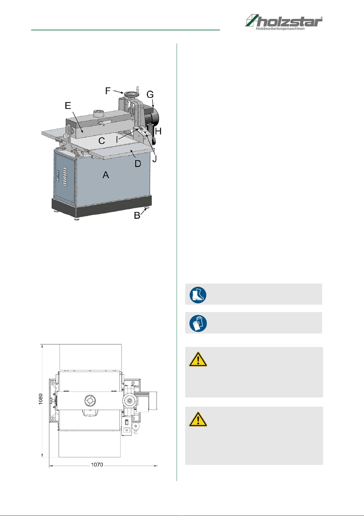
8 Description of the device ............................ 10
8.1 Space requirement ........................................... 10
9 Set up and connection................................. 10
9.1 Requirements for the installation site................ 10
10 Setting up the Cylinder Sanding Machine .. 10
10.1 Electrical connection...................................... 12
11 Commissioning .......................................... 12
11.1 Test run.......................................................... 12
12 Operation .................................................... 13
12.1 Notes on operation ........................................ 13
12.2 Starting the machine..................................... 13
12.3 Set feed rate .................................................. 14
12.4 Adjust height adjustment ............................... 14
12.5 Grinding process............................................ 14
12.6 Workflow....................................................... 15
13 Adjustment and setup work ...................... 15
13.1 Grinding belt change...................................... 15
13.2 Sandpaper cleaning....................................... 16
13.3 Adjustment of the pressure roller................... 17
13.4 Setting the height stop................................... 17
13.5 Adjusting the guide rails................................. 18
13.6 Align feed belt to grinding drum ..................... 18
14 Care, maintenance and repair................... 19
14.1 Cleaning......................................................... 19
14.2 Regular check and maintenance ................... 19
14.3 Replacing the feed belt .................................. 20
14.4 Tensioning the feed belt ................................ 21
14.5 Installation grinding rollers (Accessories) ...... 22
15 Disposal, recycling of old equipment ...... 22
15.1 Decommission ............................................... 22
15.2 Disposal of electrical equipment.................... 22
15.3 Disposal of lubricants..................................... 22
15.4 Disposal via municipal collection points......... 22
16 Troubleshooting ......................................... 23
17 Spare parts ................................................. 25
17.1 Ordering spare parts....................................... 25
17.2 Spare parts drawing....................................... 26
18 Electrical circuit diagrams ........................ 30
18.1 Electrical circuit diagram ZSM 560 ................ 30
18.2 Electrical circuit diagram ZSM 560 VARIO .... 30
19 EC - Declaration of Conformity ................. 31

Introduction
ZSM 560 | Version 1.01 3
1 Introduction
You have made a good choice by purchasing the Cylin-
der sanding machine made by HOLZSTAR.
Thoroughly read the operating instructions before
commissioning the machine.
It informs you about the proper commissioning, the in-
tended use as well as the safe and efficient operation
and maintenance of the Cylinder sanding machine. The
operating instructions are part of the Cylinder sanding
machine. Always keep it at the place of use of the Cylin-
der sanding machine. Furthermore, the local accident
prevention regulations and the general safety notes are
applicable for the field of application of the Cylinder san-
ding machine. The illustrations in these operating in-
structions serve the general comprehension and may
deviate from the actual type.
1.1 Copyright
The contents of these instructions are copyright. Their
application is admissible in the frame of the device. An
application beyond the described application is not allo-
wed without written approval of the manufacturer.For the
protection of our products, we shall register trademark,
patent and design rights, as this is possible in individual
cases. We strongly oppose any infringement of our intel-
lectual property.
1.2 Customer service
Please contact your dealer if you have questions on the
machine or if you need technical advice. They will help
you with specialist information and expert advice.
Germany:
Stürmer Maschinen GmbH
Dr.-Robert-Pfleger-Str. 26
D-96103 Hallstadt
Repair service:
Fax: 0049(0)951 96555-111
E-Mail: [email protected]
Internet: www.holzstar.de
Spare part orders:
Fax: 0049(0)951 96555-119
E-Mail: [email protected]
We are always interested in valuable experience and
knowledge gained from using the application, which then
could be shared and be valuable to develop our products
even further.
1.3 Limitation of liability
All information and notes in these operating instructions
were summarised taking the applicable standards and
rules, the state-of-the-art and our long-term knowledge
and experiences into consideration.
In the following cases the manufacturer is not liable for
damages:
- Non-observance of the operating instructions,
- Inappropriate use
- Use of untrained staff,
- Unauthorised modifications
- Technical changes,
- Use of not allowed spare parts.
The actual scope of delivery may deviate from the expla-
nations and presentations described here in case of spe-
cial models, when using additional ordering options or
due to latest technical modifications. The obligations
agreed in the delivery contract, the gen-eral terms and
conditions as well as the delivery conditi-ons of the ma-
nufacturer and the legal regulations at the time of the
conclusion of the contract are applicable.
2 Safety
This paragraph will give you an overview of all important
safety packages for the protection of the people using it
well as for a safe and undisturbed operation. Other task-
based safety notes are included in the individual chapters.
2.1 Symbol explanation
Safety instructions
Safety instructions are identified in these operating instruc-
tions by symbols. The safety instructions are introduced by
signal words that express the extent of the hazard.
DANGER!
This combination of symbol and signal word indicates
an imminently hazardous situation which, if not avoi-
ded, will result in death or serious injury.
WARNING!
This combination of symbol and signal word indicates
a potentially dangerous situation that can lead to
death or serious injury if not avoided.

4ZSM 560 | Version 1.01
Safety
Tips and recommendations
It is necessary to observe the safety notes quoted in
these operating instructions in order to reduce the risks
for personal injuries and damages to property.
2.2 Obligations of the operating com-
pany
The operating company is the person who operates the
machine for business or commercial reasons by herself,
or leaves it to a third party for use or application, and who
bears the legal product responsibility for the protection of
the user, the staff or for third parties.
Obligations of the operating company:
If the machine is used for commercial purposes, the op-
erating company must comply with the legal working
safety regulations. Therefore, the safety notes in this op-
erating manual, as well as the safety, accident preven-
tion and environment protection regulations applying for
the area of application of the machine must be met. The
following applies in particular:
- The operating company must be informed about
the applying industrial safety regulations and fur-
ther analyse hazards resulting from the special
working conditions at the place of use machine.
She must implement these in form of operating
manuals for the operation machine.
- During the entire lifetime of machine, the operating
company must verify whether the operating manu-
als prepared by her correspond to the current sta-
tus of the regulations, and must adapt these if nec-
essary.
- The operating company must unambiguously regu-
late and determine the responsibilities for installa-
tion, operation, troubleshooting, maintenance and
cleaning.
- The operating company must ensure that all per-
sons who work with machine, have read and un-
derstood this manual. Furthermore she must in-
struct the staff in regular intervals and inform them
about the hazards.
- The operator must provide the necessary protec-
tive equipment to the staff and order the use of the
necessary protective equipment in a binding way.
Furthermore the operating company is responsible to
keep the Machine always in a technically flawless state.
Thus, the following applies:
- The operator must ensure that the maintenance in-
tervals described in this manual are kept.
- The operator must have all safety devices checked
regularly for their good working order and their in-
tegrity.
CAUTION!
This combination of symbol and signal word indicates
a potentially dangerous situation that can result in
minor injury if it is not avoided.
DANGER!
This combination of symbol and signal words indi-
cates a possibly dangerous situation which may lead
to property and environmental damages if they are
not avoided.
NOTE!
This combination of symbol and signal words indi-
cates a possibly dangerous situation which may lead
to property and environmental damages if they are
not avoided.
Tips and recommendations
This symbol highlights useful tips and recommenda-
tions as well as information for an efficient and trou-
ble-free operation.

Safety
ZSM 560 | Version 1.01 5
2.3 Qualification of personnel
The different tasks described in this manual represent
different requirements to the qualification of the persons
entrusted with these tasks.
Only persons reliable working procedures can be ex-
pected from, are allowed to perform all works. Persons
the responsiveness of which is affected by e. g. drugs,
alcohol or medication, are not allowed to work with the
machine.
The qualifications of the personnel for the different tasks
are mentioned below:
Operator:
The operator is instructed by the operating company
about the assigned tasks and possible risks in case of
improper behaviour. Any tasks which need to be perfor-
med beyond the operation in the standard mode must
only be performed by the operator if it is indicated in
these instructions and if the operating company expres-
sively commissioned the operator.
Electrical specialist:
Due to his professional training, knowledge and experi-
ence as well as his knowledge of respective standards
and regulations the electrical specialist is able to perform
works on the electrical system and to recognise and
avoid any possible dangers himself.
Specialist staff:
Due to their professional training, knowledge and experi-
ence as well as their knowledge of relevant regulations
the specialist staff is able to perform the assigned tasks
and to recognise and avoid any possible dangers them-
selves.
Manufacturer:
Certain works may only be performed by specialist per-
sonnel of the manufacturer. Other personnel is not au-
thorized to perform these works. Please contact our cus-
tomer service for the execution of all arising work.
2.4 Personal protective equipment
The personal protective equipment serves to protect per-
sons against impairments of safety and health while wor-
king. The staff has to wear personal protective equip-
ment while performing different works on and with grind-
ing system which are indicated in the individual paragra-
phs of these instructions.
The personal protective equipment is explained in the
following paragraph:
WARNING!
Danger in case of insufficient quali-
fication of the staff!
Insufficiently qualified persons cannot estimate the
risks while using machine and expose themselves
and others to the danger of severe injuries.
- Have all works only performed by qualified persons.
- Keep insufficiently qualified persons and children
out of the working area.
Hearing protection
Hearing protection helps to protect the hearing from
harmful noise and other loud sounds.
Head protection
The industrial helmet protects the head against fal-
ling objects and bumping against fixed objects.
Eye protection
The protective goggles protect the eyes against parts
flying off and splashes of liquids.
Breathing protection
The breathing protection serves for protecting the
respiratory passages and the lung against the intake
of dust particles.
Protective gloves
The protective gloves serve to protect the hands
against sharp components as well as against friction,
abrasions or deep injuries.
Safety boots
The safety boots protect the feet against crushes, fal-
ling parts and slipping over on slippery underground.
Protective clothes
The protective clothes are tight clothes of little tensile
strength.

6ZSM 560 | Version 1.01
Safety
2.5 Safety labels at the Cylinder San-
ding Machine
The following safety markings are attached to the Cylin-
der Sanding Machine, which must be observed and follo-
wed.
Fig. 1: Safety labels
The safety markings attached to the machine must not
be removed. Damaged or missing safety markings can
lead to incorrect actions, personal injury and damage to
property. They must be replaced immediately.
If the safety markings are not recognizable and compre-
hensible at first glance, the machine must be taken out of
operation until new safety markings have been applied.
2.6 Safety devices
All necessary measures for connection are described in
this operating manual. The connection may only be
made after reading and understanding the instructions.
In case of any ambiguity, contact the dealer.
Installation errors, including electrical
connection errors, are not covered by the warranty.
Before connecting or disconnecting the machine, the po-
wer connection must be interrupted.
2.7 General safety instructions
- Read the operating instructions before operating
the machine.
- Keep the work area clean and well lit. Cluttered or
dark areas invite accidents. Keep the floor free of
tripping hazards and dirt.
- Do not operate power tools in potentially explosive
atmospheres, e.g. in the presence of flammable li-
quids, gases or dust. Power tools produce sparks
that can ignite dust or the fumes.
- Do not expose the machine to rain or wet conditi-
ons.
- Check power supply at regular intervals. Do not
use defective cables.
- Never use the cord to carry, pull or unplug the ma-
chine.
- Keep the cable away from heat, oil, sharp edges or
moving parts.
- Never touch rotating or moving parts.
- Never work with the machine when you are not
concentrated.
- Keep children and untrained personnel away from
the machine.
- As soon as a safety device has been triggered or
has failed, the machine may only be started up if
you have eliminated the cause of the fault and
have made sure that there is no danger to persons
or objects.
- Always report electrical faults to an electrician.
- Switch off the machine when work is interrupted.
- Wear appropriate safety clothing (safety shoes,
safety goggles, respiratory protection, etc.).
- Check safety devices for correct function before
starting work. If safety devices are damaged, the
machine must not be put into operation.
- Read and understand the safety instructions atta-
ched to the machine.
- Carry out regular maintenance work.
- Do not overload the machine.
- If the machine does not operate normally, inform
the supervisor immediately.
- Use caution when people are in the work area.
- Never modify electrical or safety devices.
- Never remove mechanical or electrical safety de-
vices.
- Always keep hands away from the working area of
the grinding drum.
- Check feed belt from time to time to make sure
there is no dirt or sawdust between components.
- Pay special attention when transporting or reas-
sembling; follow transport instructions.
- If possible, secure the machine at the workplace.
- Never carry out a grinding operation if the cover of
the grinding drum has been removed.
- Before starting work, check all screws and safety
devices for tightness.
- Never force the workpiece into the feed opening of
the machine.
- Allow the grinding drum to reach full speed before
starting work.
- Only process wood that has as few knots as pos-
sible.
- Make sure that the workpiece is free of nails,
screws or other foreign bodies that could damage
the grinding drum or the feed belt.
- Use only original spare parts and accessories.

Intended use
ZSM 560 | Version 1.01 7
3 Intended use
The Cylinder Sanding Machine ZSM 560 and ZSM 560
Vario is designed for surface sanding of wood or wood-
like materials. The machine must not be set up and ope-
rated in potentially explosive atmospheres and only in
dry and ventilated rooms.
Intended use also includes compliance with all the infor-
mation in these instructions. Any use beyond the inten-
ded use or any other use is considered misuse. Un-
authorized conversions or modifications to the grinding
machine can invalidate the CE conformity of the cylindri-
cal grinding machine and are prohibited.
Stürmer Maschinen GmbH accepts no liability for design
and technical modifications to the cylindrical grinding
machine.
3.1 Foreseeable misuse
- Simultaneous machining of several workpieces.
- Machining of unacceptable materials such as me-
tals.
- Bypassing or modifying the safety devices.
- Installation of spare parts and use of accessories
not approved by the manufacturer.
- Maintenance work on an unsecured machine.
- Machining of flammable or harmful materials.
- Use of the cylindrical grinding machine in an indu-
strial environment.
3.2 Residual risks
The machine has been built with modern technology ac-
cording to the recognized safety rules. Nevertheless,
some residual dangers may still exist.
- The rotating guide drum can cause injuries to fin-
gers and hands.
- Ejected workpieces can cause injuries if the work-
piece is not properly secured or fed.
- Wood chips and sawdust can be hazardous to
health. Be sure to wear personal protective equip-
ment such as safety glasses and dust mask. Use
an extraction
- system.
- Injuries due to defective grinding belts. Check the
grinding belts regularly to ensure that they are in
perfect condition.
- Hearing damage due to noise exposure when wor-
king on the machine. Wear suitable hearing protec-
tion.
- Health hazard due to long hair and loose clothing
being drawn in. Wear personal protective equip-
ment such as hair nets and tight-fitting clothing.
- Risk of injury from rotating grinding belts when
switching on the machine.
- Remove the adjusting key and workpieces before
switching on the machine. Risk of injury from rota-
ting grinding belts ! Keep hands away from the
grinding belts.
- Risk of injury from electric shock when using a da-
maged extension cord. Only use undamaged ex-
tension cables that have been tested by a specia-
list.
DANGER!
The non-intended use of the Cylinder Sanding Ma-
chine as well as the disregard of the safety regulations
or the operating instructions exclude a liability of the
manufacturer for resulting damages to persons or ob-
jects and cause an expiration of the warranty claim!

8ZSM 560 | Version 1.01
Technical Data
4 Technical Data
4.1 Table
4.2 Type plate
Fig. 2: Type plate ZSM 560
5 Scope of delivery
- Tool
- Grinding roller K80
- Operating instructions
6 Accessories
ZSM 560 Vario
- Lamellar grinding roller K240
Item number: 5913856
- Nylon grinding roller
Item number: 5913857
- Wire brush roller Ø 0,4mm
Item number: 5913858
ZSM 560 and ZSM 560 Vario
- Grinding roller 50.000x80mm K60
Item number: 5918760
- Grinding roller 50.000x80mm K80
Item number: 5918780
- Grinding roller 50.000x80mm K100
Item number: 5918710
- Grinding roller 50.000x80mm K120
Item number: 5918712
- Grinding roller 50.000x80mm K150
Item number: 5918715
- Grinding roller 50.000x80mm K180
Item number: 5918718
- Grinding roller 50.000x80mm K220
Item number: 5918722
Model ZSM 560 ZSM 560
Vario
Length 1070 mm 1070 mm
Width/depth 1080 mm 1080 mm
Height 1150 mm 1200 mm
Weight 116 kg 119 kg
Supply voltage 230 V 230 V
Sanding belt length 3280 mm 3280 mm
Sanding belt width 78 mm 78 mm
Speed 1400 min⁻¹ 0-1800 min⁻¹
Sanding surface
width
555 mm 555 mm
Max. sanding height 80 mm 80 mm
Sand roller diameter 132 mm 132 mm
Drive roller diameter 19 mm 19 mm
Work table length 592 mm 592 mm
Work table width 505 mm 505 mm
Work table height 695 mm 695 mm
Min. workpiece
height
5 mm 5 mm
Min. workpiece
height
80 mm 80 mm
Min. workpiece
length
120 mm 160 mm
Feed speed 0-3.5 m/min 0-3.5 m/min
Extraction port dia-
meter
100 mm 100 mm
Starting current 27 A 25 A
Rated current 8.8 A 5.3 A
Feed motor output 80 W 80 W
Drive motor output 1,5 kW 1,5 kW

Transport, Packaging, Storage
ZSM 560 | Version 1.01 9
7 Transport, Packaging, Sto-
rage
7.1 Delivery and Transport
Delivery
Check the cylinder sanding machine after delivery for vi-
sible transport damage. If you discover any damage to
the Cylinder sanding machine, immediately report it to
the transport company or the dealer.
Transport
Improper transport is accident-prone and can cause da-
mage or malfunctions for which we do not grant any liabi-
lity or guarantee.
Transport the scope of delivery secured against shifting
or tilting with a sufficiently dimensioned industrial truck to
the installation site.
General risks during internal transport
Devices may only be transported by authorized and qua-
lified persons. Act responsibly during transport and al-
ways consider the consequences. Refrain from daring
and risky actions.
Gradients and descents (e.g. driveways, ramps and the
like) are particularly dangerous. If such passages are
unavoidable, special caution is required.
Before starting the transport check the transport route for
possible danger points, unevenness and disturban-ces
as well as for sufficient strength and load capacity.
Danger points, unevenness and disturbance points must
be inspected before transport. The removal of danger
spots, disturbances and unevenness at the time of trans-
port by other employees leads to considerable dangers.
Careful planning of internal transport is therefore essen-
tial.
7.2 Packaging
All packaging materials and packing aids used in the
Cylinder Sanding Machine are recyclable and must al-
ways be sent for material recycling.
Shred cardboard packaging components and take them
to the waste paper collection.
The films are made of polyethylene (PE) and the cushio-
ning parts of polystyrene (PS). These materials should
be taken to a collection point for recyclable materials or
to your local waste disposal company.
Keep the packaging material out of the hands of child-
ren, as some plastic packaging may pose a choking ha-
zard, etc. when used as a toy.
7.3 Storage
The cylinder grinding machine must be thoroughly cle-
aned before it is stored in a dry, clean and frost-free env-
ironment. Cover the machine with a protective tarpaulin.
WARNING!
Severe or fatal injuries may occur if parts of the
machine tumble or fall down from the forklift
truck, pallet truck or from the transport vehicle.
Follow the instructions and information on the trans-
port box.
Note the total weight of the machine. The weight of
the machine is indicated in the "Technical data" of the
machine. When the machine is unpacked, the weight
of the machine can also be read on the rating plate.
Only use transport devices and load suspension gear
that can hold the total weight of the machine.
WARNING!
The use of unstable lifting and load suspension
equipment that might break under load can cause
severe injuries or even death. Check that the lifting
and load suspension gear has sufficient load-bea-
ring capacity and that it is in perfect condition.
Observe the accident prevention regulations issued
by your Employers Liability Insurance Association or
other competent supervisory authority, responsible
for your company.
Fasten the loads properly.
WARNING: DANGER OF TIPPING
The device may be lifted unsecured by a maximum
of 2cm.
Employees must be outside the danger zone, the
reach of loads.
Warn employees and, if necessary, advise employ-
ees of the hazard.

10 ZSM 560 | Version 1.01
Description of the device
8 Description of the device
Illustrations in these operating instructions may de-
viate from the original
Fig. 3: Cylinder Sanding Machine ZSM 560
A Machine base
B Feet
C Feed belt
D Extension table
E Grinding roller cover
F Handwheel for height adjustment
G Motor
H Feed belt drive
I On / Off switch
J Feed controller
8.1 Space requirement
Fig. 4: Space requirement
9 Set up and connection
9.1 Requirements for the installation
site
The cylindrical grinding machine must be set up on a le-
vel and solid surface in a stable manner. It must be ensu-
red that there is sufficient freedom of movement for wor-
king. There must be at least 1 m clearance from the wall
to the Cylinder Sanding Machine on each side. The in-
stallation site should meet the following criteria:
- The substrate must be level, firm and vibration-
free.
- The surface must not allow any lubricants to pass
through.
- The installation or work area must be dry and well
ventilated.
- No machines causing dust and chips should be
operated in the vicinity of the machine.
- There must be sufficient space for the operating
personnel, for material transport and for setting
and maintenance work.
- The installation site must have good lighting.
10 Setting up the Cylinder Sanding
Machine
Wear safety shoes!
Wear protective gloves!
CAUTION!
Risk of injury due to an unstable machine!
Check the stability of the machine after setting it up on
a stable surface.
CAUTION!
Observe the weight of the machine!
The machine may only be set up by two persons to-
gether.
Check the auxiliary equipment for sufficient dimensio-
ning and load-bearing capacity.

Setting up the Cylinder Sanding Machine
ZSM 560 | Version 1.01 11
The machine must be fully assembled before it can be
put into operation. To ensure that the assembly process
runs smoothly, first clean any parts that are covered or
coated with a rust inhibitor (if applicable). Avoid chlorine-
based solvents, such as acetone or brake cleaner, which
can damage painted surfaces.
Proceed as follows to assemble the machine:
Step 1: Unpack the machine and check the carton con-
tents for the following.
Fig. 5: Mounting parts of the machine
Step 2: Insert the 4 rubber feet (Fig.6) into the holes un-
derneath the machine.
Fig. 6: Insert rubber feet
Step 3: Mount the table extension (Fig.7) to the feed
opening of the machine with screws and was-
hers. The height of the table extension can be
adjusted by turning the adjustment screws.
Fig. 7: Mount table extension
Step 4: Mount the handwheel for height adjustment on
the machine head using the screw, washer and
cap nut.
Fig. 8: Mount handwheel
Screw
Table extension
Table
connection
Table
extension

12 ZSM 560 | Version 1.01
Commissioning
Step 5: Place the suction nozzle on the opening of the
grinding drum cover and attach a suction hose
to the suction nozzle using a hose clamp..
Fig. 9: Mount suction nozzle
Step 6: Connect the suction hose to a suitable suction unit.
10.1 Electrical connection
When connecting the power, make sure that the characteri-
stics (voltage, mains frequency, fuse protection) match the
specifications on the nameplate and for the motor.
1. The cables must be connected directly to the machine
without extension cables.
2. For safe operation, check the grounding (see the wi-
ring diagram).
3. If the motor is overloaded, it switches off automati-
cally. After a cooling time of approx. 2 minutes and eli-
mination of the cause of the overload, the machine
can be restarted.
4. The customer's mains connection and the extension
cables used must comply with the regulations.
11 Commissioning
11.1 Test run
Once assembly is complete, perform a test run to ensure
that your machine is running properly and is ready for re-
gular operation. Make sure that all tools and objects
used during setup have been removed from the machine
and that the grinding drum is safely above the feed belt
so that no contact can occur during the test run.
The test run consists of checking the following items:
- Switch on the machine and check for correct ope-
ration.
- Check safety shut-off mechanism on switch and
cover.
- Check rotary switch for variable feed speed.
- Check that the grinding roller can rotate safely
above the feed belt and does not come into contact
with it.
DANGER!
Danger to life from electric shock!
There is a danger to life in case of contact with live
components. Switched-on electrical components can
perform uncontrolled movements and lead to serious
injuries.
DANGER!
All work on the electrical installation may only be car-
ried out by a qualified electrician in order to avoid the
risk of personal injury due to improperly performed
work.
DANGER!
The machine must be connected to an extraction sy-
stem before start-up.
DANGER!
Before commissioning, check the electrical connec-
tion, cables and contacts.
Wear hearing protection!
Wear protective goggles!
Wear safety shoes!
Wear protective work clothing!
Wear dust mask!

Operation
ZSM 560 | Version 1.01 13
The following settings have been set in advance at the
factory and must be checked before commissioning the
machine.
- Belt tension
- Belt run of the feed belt
- Alignment from feed belt to drum
- Pressure roller adjustment
- Adjustment of the height stop
12 Operation
12.1 Notes on operation
The cylindrical grinding machine has a drum driven by
the motor. The workpiece is fed with the automatic feed
against the rotation of the drum. However, a certain level
of experience is necessary to work efficiently.
The following recommendations should assist in
processing:
- The operator should have basic knowledge with
this type of machines.
- Material removal and surface quality is better when
working in several passes at low infeed and higher
feed rate.
- The best surface finish can be obtained when grin-
ding in the direction of the grain.
- The optimum infeed requires some experience and
depends on the sanding belt grit, feed speed and
type of wood.
- Remove nails and other foreign objects from the
workpiece before machining.
- Sanding wood with moisture content above 20%
causes unnecessary wear on sandpaper and mo-
tors, increases the risk of kickback, and produces
poor results.
- Ensure that all workpieces are securely held and
guided during machining.
- Only machine a workpiece that is resting securely
on the table.
- Remove chips and workpiece parts only when the
machine is stationary.
12.2 Starting the machine
With the following steps the machine can be started and
the machining process can be executed:
Step 1: Make sure that the electrical connection is cor-
rect.
Step 2: Plug in the power plug and press the start button.
Start button of the ZSM 560 VARIO machine is located on
the control box (Fig.12).
Step 3: Switch on automatic table feed..
DANGER!
Danger to life from electric shock!
There is a danger to life in case of contact with live
components. Switched-on electrical components can
perform uncontrolled movements and lead to serious
injuries.
- Disconnect the power plug before starting any adju-
stments on the machine.
WARNING!
Danger to life!
There is danger to the life of the operator and other
persons if they do not observe the following rules.
- The Cylinder Sanding Machine may only be opera-
ted by an instructed and experienced person.
- The operator must not work if he is under the influ-
ence of alcohol, drugs or medication.
- The operator must not work if he is overtired or suf-
fers from diseases that impair concentration.
- The Cylinder Sanding Machine may only be opera-
ted by one person. Other persons must keep away
from the working area during operation.
CAUTION!
Risk of crushing!
Improper work on the machine may result in injury to
the upper limbs.
Wear hearing protection!
Wear protective goggles!
Wear safety shoes!
Wear protective work clothing!
Wear dust mask!

14 ZSM 560 | Version 1.01
Operation
Fig. 10: Starting the ZSM 560 machine
12.3 Set feed rate
When selecting the feed rate for machining, consider va-
riables such as the hardness and condition of the wood,
the grit of sandpaper used, the desired surface finish,
etc. As a guide, wide or hard workpieces and the use of
finer grit sandpaper require a slower feed rate. The goal
in setting the proper feed rate is to achieve the desired
results for the operation without damaging the work-
piece.
To increase the feed rate, turn the variable feed rate
knob clockwise.
Fig. 11: Set feed rate
12.3.1 Variable feed rate ZSM 560 Vario
The variable feed rate can be set on the control box.
Fig. 12: Set variable feed rate
12.4 Adjust height adjustment
The proper depth of cut for surface grinding depends on
many variables, such as the hardness of the wood, the
width of the workpiece, and the feed rate. Generally, for
coarser grits or softer woods, a 1⁄4 revolution of the
handwheel (0.8 mm depth of cut) per pass is acceptable.
A 1⁄8 turn of the handwheel (0.4 mm depth of cut) is re-
commended for finer grits or harder woods.
Proceed as follows to set the height:
Step 1: Loosen the clamping screw (Fig.13).
Step 2: Turn the height adjustment handwheel counter-
clockwise to lower the grinding drum.
Step 3: Once the correct cutting depth for your operation
is set, retighten the clamping screw (Fig.13).
Fig. 13: Height adjustment
12.5 Grinding process
12.5.1 Rules for grinding on the machine
The grinding operation may only be performed by quali-
fied personnel experienced in working on these machi-
nes. The workpiece is fed with the automatic feed
against the direction of the drum. Feed the workpiece
with the thicker end first. Do not process heavily twisted
or bent workpieces or those whose thickness varies
greatly. Support long workpieces with roller blocks. Use
the height adjustment handwheel to set the grinding
drum to the desired chip removal rate.
Follow these precautions to ensure a safe grinding
process and high-quality results:
- Replace the sandpaper with a higher grit to
achieve a finer final result.
- When making multiple passes on the workpiece, do
not lower the sanding drum more than 1⁄32" or 1⁄4".
- If possible, feed the workpiece to the grinding drum
at a 60° angle. This will ensure more effective ma-
terial removal, less stress on the motor, and more
even wear on the abrasive paper.
Engine
Start button
Automatic
table feed
Table feed
rate
Screw
Scale
Hand wheel

Adjustment and setup work
ZSM 560 | Version 1.01 15
- Extend the life of the abrasive paper by regularly
using an abrasive pad.
- DO NOT edge grind workpieces. This can cause
boards to recoil and cause serious injury.
- Replace damaged and worn sanding belts immediately.
12.6 Workflow
Step 1: Check the correct mounting of the sanding paper
on the sanding drum.
Step 2: Check the workpiece for foreign bodies such as
nails.
Step 3: Place the workpiece to be machined on the work
table of the machine.
Step 4: Adjust the chip removal with the handwheel (B,
Fig. 14).
set.
Step 5: Start the machine (D, Fig.14).
Step 6: Start feed (E, Fig.14) and select feed speed.
Step 7: Start the suction system.
Step 8: Feed the workpiece (if possible, place the work-
piece at a slight angle, as the sandpaper load
is lower here).
Step 9: Check the ground surface.
Step 10: Switch off the extraction system.
Step 11: Switch off the machine.
Fig. 14: Workflow
13 Adjustment and setup work
13.1 Grinding belt change
Proceed as follows to remove the grinding belt:
Step 1: Switch off the cylinder grinding machine and dis-
connect the power plug.
Step 2: Loosen the locking hook of the cover below the
handle.
Step 3: Swing the cover up to access the sanding drum
and sandpaper.
Step 4: Reach under the right clamp and press the lever
to release the sandpaper.
Fig. 15: Clamping device right
Step 5: Unwind the sandpaper strip from the drum until
you reach the clamping device on the left side.
NOTE!
Before adjustment and setup work, the
The machine must be secured against start-up.
Pull out the mains plug!
Wear protective work clothing!
Wear protective gloves!
Clamping device

16 ZSM 560 | Version 1.01
Adjustment and setup work
Fig. 16: Clamping device left
Step 6: Reach under the left clamp and press the lever to
remove the sandpaper from the machine.
Proceed as follows to install the grinding belt:
Step 1: Reach under the left clamp and press the lever.
Step 2: Insert the end of the new sandpaper into the
clamping device and align the sandpaper with
the left side of the drum slot.
Step 3: Close the lever to clamp the sandpaper.
Step 4: Pull the sandpaper to make sure it is securely
and tightly clamped.
Step 5: Hold the sandpaper under tension with one hand
and turn the drum clockwise with the other
hand to wind the sandpaper.
Fig. 17: Wind up sandpaper
Step 6: Lift the right clamp forward and press the lever.
Step 7: Insert the end of the sandpaper at the drum slot
between the clamp and the lever.
Step 8: Close the lever to clamp the sandpaper.
Step 9: Make sure the sandpaper is tight and flush
against the drum, edges do not protrude more
than 1⁄8" and do not overlap.
Step 10: Close the cover and turn on the machine.
13.1.1 Sandpaper selection
Choosing the right abrasive belt grit is extremely import-
ant for optimizing grinding performance. Always grind
with a coarse grit first and then gradually switch to finer
grits. Do not skip more than one grit level. Grain sizes
that are too fine and worn grinding belts can leave burn
marks on the workpiece.
Grit 36:
Extra coarse, maximum stock removal e.g. for paint
removal.
Grit 60- 80:
Surface and light calibration, most common grits
Grit 100 and 120:
Surfaces and fine sanding
Grit 150, 180 and 220:
Fine sanding only
13.2 Sandpaper cleaning
Clean the sandpaper regularly with a fine brush.
Removing the sanding dust deposits will significantly ex-
tend the life of the sandpaper.
Step 1: Start the grinding drum with the cover open.
Step 2: Guide the brush along the rotating grinding drum.
It is recommended to remove the resulting
abrasion with a brush after the machine has
been switched off.
Turning the abrasive paper can increase its service life.
New grain tips are used here.
Fig. 18: Sandpaper cleaning
NOTE!
Align the direction arrow printed on the bottom of the
sandpaper with the direction of rotation of the drum.
Clamping device

Adjustment and setup work
ZSM 560 | Version 1.01 17
13.3 Adjustment of the pressure roller
The height of the pressure rollers is set below the grin-
ding drum to hold the workpiece firmly against the feed
belt as it passes through the grinder and to prevent the
workpiece from kicking back.
Fig. 19: Pressure rollers
The pressure that the pressure rollers exert on the work-
piece while the workpiece is being machined is control-
led by pressure springs and adjusting screws.
Fig. 20: Adjustment screws pressure rollers
The correct pressure on the workpiece helps to prevent
kickback. However, if the pressure on the workpiece
from the rear pressure roller increases, the pressure on
the grinding drum also increases. In this case, reduce
the pressure on the rear pressure roller.
If you want to increase or decrease the pressure that
these rollers exert on the workpiece, perform the follo-
wing steps.
Step 1: Switch off the machine and disconnect the power
plug.
Step 2: Loosen the locking hook of the cover below the
handle.
Step 3: Swing the cover up to include access to the pres-
sure roller adjustment screws.
Step 4: To increase the pressure exerted by the rollers,
tighten all four screws in small, even turns and
test the pressure of the rollers by pushing them
upward. Conversely, loosen the adjustment
screws to decrease the pressure.
Step 5: Perform test run. If the workpiece tends to recoil,
decrease the pressure by turning the screws
counterclockwise.
Step 6: If the workpiece slips on the belt, increase the
pressure by turning the screws clockwise one
turn and perform the test again.
13.4 Setting the height stop
The adjustment screw, which protrudes through the bot-
tom of the frame, serves as a stop to prevent the grinding
drum from coming into contact with the feed belt when
adjusting the height.
Fig. 21: Height stop adjustment screw
The setting of the screw was set correctly at the factory.
However, if it is necessary to readjust the stop screw, per-
form the following steps.
Step 1: Switch off the machine and disconnect the power
plug.
Step 2: Make sure that the belt is correctly tensioned.
Step 3: Crank the grinding drum to the highest position.
Step 4: Loosen the hex nut on the adjustment screw and
adjust the height of the screw that protrudes
above the frame so that it protrudes no less
than 6.3 mm.
Pressure rollers
Screws
Screws

18 ZSM 560 | Version 1.01
Adjustment and setup work
Step 5: Tighten the hex nut and lower the grinding drum
until the adjustment screw touches the frame
of the holder.
Step 6: Ensure that the grinding drum is at least 4.8 mm
above the surface of the feed belt.
13.5 Adjusting the guide rails
The guide rails exert pressure on the slides of the grin-
ding head. This allows the grinding head assembly to
move up and down precisely when using the handwheel.
If the ledges are too loose, the grinding roller will be pus-
hed up during operation, resulting in poor grinding re-
sults.
If the bars are too tight, it is difficult to adjust the grinding
roller height, resulting in excessive wear.
Proceed as follows to adjust the bars:
Step 1: Switch off the machine and disconnect the power
plug.
Step 2: Loosen the lock nut on both guides.
Fig. 22: Loosen guide sides
Step 3: Screw each of the six cap screws in or out in
short, equal turns. Then turn the height adjust-
ment handwheel to test the movement of the
grinding head.
Note: Tighten the cap screws to increase the
pressure on the bar.
Fig. 23: Set guide sides
Step 4: Repeat step 3 until you are satisfied with the grin-
ding head movement.
Step 5: Tighten the lock nut on the two guides again.
13.6 Align feed belt to grinding drum
To ensure a good grinding result, the feed belt and grin-
ding drum must be parallel to each other from side to
side. Otherwise, more material will be removed from one
side of the workpiece than the other. The goal of this
procedure is to set the parallelism of the feed belt and
sanding drum within 0.05" difference from side to side.
Fig. 24: Parallelism of feed belt and grinding drum
Proceed as follows to set the parallelism of the feed belt
to the grinding drum:
Step 1: Switch off the machine.
Step 2: Make sure that the guide pads are set correctly.
Step 3: Select a workpiece that has an equal thickness on
each side.
Step 4: Switch on the machine.
NOTE!
If the grinding drum is not at least 4.8 mm above the
feed belt, repeat this process until the grinding drum is
at least 4.8 mm above the feed belt.
Nut
Guide
Screws
Guide strip
Correct
Incorrect
Feed belt
Feed belt
Grinding drum
Grinding drum

Care, maintenance and repair
ZSM 560 | Version 1.01 19
Step 5: Make several light sanding passes without turning
or flipping the board.
Step 6 : Remove the workpiece and switch off the machine.
Step 7: Perform measurement at location A and B as
shown in Figure 25..
- If dimension "A" is less than "B", loosen or remove
the screws on the right hinge support. Remove or
place a washer between the support and the frame
to compensate for the difference between "A" and
"B.
- If dimension "B" is less than "A", loosen or remove
the screws on the left hinge support. Remove or
place a washer between the support and the frame
to compensate for the difference.
Fig. 25: Set parallelism of feed belt to grinding drum
Step 8: Repeat steps 1-5 to verify adjustment. If neces-
sary, repeat step 5 until the parallelism of the
feed belt and grinding drum is within 0.05" from
side to side.
14 Care, maintenance and repair
14.1 Cleaning
Step 1: Disconnect the power plug from the socket.
Step 2: Empty and clean the suction device.
Step 3: Clean the machine of sawdust and sawdust.
Step 4: Check fastening screws and safety devices for
tightness and tighten them.
Step 5: Thoroughly clean resin deposits on the machine
using resin remover.
Step 6: Spray all unpainted metal surfaces with some
anti-rust spray.
Step 7: Inspect the machine for damage to safety de-
vices and the sanding belt. If necessary, carry
out the repair or arrange for it to be carried out,
observing the safety instructions..
14.2 Regular check and maintenance
Lubrication of the machine
Regularly check the grinding belt for defects.
1. Replace a damaged grinding belt immediately. Check
the correct setting of the feed belt at regular intervals.
Lubricate monthly all moving parts (Fig.26) such as
threaded spindle, pulleys and bearing bushes inclu-
ding the height stop, sliding surfaces and bushes
connected to the height adjustment mechanism. Do
not use oil or grease for this purpose as it tends to bind
sawdust.
DANGER!
Danger to live due to electrical
voltage!
Contact with live components can be fatal. Activated
electrical components can execute uncontrolled mo-
vements and cause serious injuries.
- Switch off the machine before carrying out cleaning
and maintenance work and unplug the power cord.
- Connections and repairs of electrical equipment
may only be performed by a qualified electrician.
Left Right
bracket bracket
Wear safety gloves!
Wear protective clothing!
NOTE!
Never use harsh cleaning agents for cleaning. This
can lead to damage or destruction of the device.
Provide adequate ventilation when using solvents.

20 ZSM 560 | Version 1.01
Care, maintenance and repair
Fig. 26: Lubrication
2. Clean the machine at regular intervals. Vacuum the
dust from inside the drum to avoid vibrations (use a va-
cuum cleaner).
3. Regularly check the tightness of all frame screws and
motor/drum mounting screws.
4. Check motor/drum mounting screws and feed rollers for
tightness after approximately 50 hours of operation.
5. Check daily that the extraction system is functioning
adequately. Replace damaged safety devices immedi-
ately.
Clean grinding belt
During use, the sanding belt and guide may become clogged
with sawdust, resulting in insufficient sanding, damage to the
workpiece, and burn marks on the workpiece. With the ma-
chine switched off and not connected to the power supply,
occasionally check the condition of the sandpaper on the
sanding drum for clogging. This should be done frequently,
especially with resinous woods.
Step 1: Switch off the machine and disconnect the power
plug.
Step 2: Set the feed control to the lowest feed setting.
Avoid contact with conveyor belt.
Step 3: Open the protective cover to expose the grinding
drum and belt.
Step 4: Use a long cleaning strip to keep hands away
from the rotating drum.
Step 5: Turn on the machine, grasp the cleaning strip of
the belt with two hands and place the cleaning
strip on the casting where the grinding drum is
located. Gently lower the cleaning rod onto the
rotating drum and move the cleaning rod from
side to side to remove the whipped sawdust.
Step 6: When cleaning is complete, remove the stick, turn
off the power, and close and lock the dust
cover.
14.3 Replacing the feed belt
If the feed belt is excessively worn or damaged, it can be
easily replaced.
Proceed as follows to replace the conveyor belt:
Step 1: Switch off the machine and disconnect the power
plug.
Step 2: Disassemble the clamping screw and washer of
the grinding head carrier.Remove the hexago-
nal screws, spacers and washers from the un-
derside of the carrier and remove the carrier.
Fig. 27: Replace feed belt
Step 3: Release the feed belt completely by loosening the
clamping screws on the left and right.
Step 4: Remove the feed belt holder by loosening the
screws.
Step 5: Pull off the feed belt from the side.
WARNING!
Do not operate the grinding machine with the drum
cover open. Exercise extreme caution when perfor-
ming drum cleaning on your grinding machine. Do not
wear long-sleeved shirts, ties or jewelry. Tie back long
hair when cleaning the drum. Failure to follow this
warning can result in serious injury.
Spindle
Guide
Bracket
Grinding head
support
This manual suits for next models
1
Table of contents
Other Holzstar Sander manuals