SOMMER RG-30 User manual

Sommer Messtechnik
All rights reserved.
Manual
Setup version 2.38 (Firmware 2.96)
25 November, 2019
RG-30, RG-30a
Flow velocity Measurement System

The Copyrights for this manual are exclusively owned by
Sommer Messtechnik
6842 Koblach
Austria
This manual or parts of it may only be copied or passed on to third parties with written permission
of Sommer Messtechnik. This applies to printed as well as digital issues of this manual.
Sommer Messtechnik
Strassenhäuser 27
6842 Koblach
Austria
www.sommer.at
E office@sommer.at
T +43 5523 55989
F +43 5523 55989-19
Validity
This manual applies to the Flow velocity Measurement System with the setup version 2.38, includ-
ing all its subversions.
Created: 19 Sept, 2018 Last update: 25 November, 2019
EU conformity
This product is in conformity with the following standards:
EMC 2014/30/EU EN 301 489-1 V1.9.2
LVD 2014/35/EU EN 62311:2008
EN 62368-1:2014
RED 2014/53/EU EN 300 440-2 V1.4.1
RoHS II 2011/65/EU
RoHS III 2015/863/EU
FCC compliance
This device complies with Part 15 of the FCC Rules. Operation is subject to the following two con-
ditions: (1) This device may not cause harmful interference, and (2) This device must accept any
interference received, including interference that may cause undesired operation.
FCC ID: UXSIMS944
Feedback
Should you come across any error in this manual, or if you miss information to handle and operate
the RG-30 we are very grateful for your feedback to office@sommer.at.

Safety information
Please read this manual carefully before installing or operating this equipment. Non-compliance
with the instructions given in this manual can result in failure or damage of the equipment or may
put people at risk by injuries through electrical or mechanic impact.
lInstallation and electrical connections must be carried out by qualified personnel familiar
with the applicable regulations and standards.
lInstallation of equipment on towers, bridges and in discharge channels poses the risk of fall-
ing, slipping or dropping of objects. Contact your safety officer or consult applicable safety
regulations for precautions and proper personal safety equipment.
lDo not perform any installations in bad weather conditions, e.g. thunderstorms.
lPrior to installation of equipment inform the owner of the measurement site or the authority
responsible for it. Upon completion, secure the installation from trespassers.
lMaintenance and repair must be performed by trained personnel or an engineer of Sommer
Messtechnik. Only replacement parts supplied by Sommer Messtechnik should be used for
repairs.
lMake sure that NO power is connected to the equipment during installation and wiring.
lOnly use a power supply that complies with the power rating specified for this equipment.
lKeep equipment dry during wiring and maintenance.
lIf applicable, it is recommended to use accessories of Sommer Messtechnik with this equip-
ment.
lFor SAFETY-RELEVENT APPLICATIONS consider using a redundant system with additional data
validation checks.
Disposal
After this device has reached the end of its lifetime, it must not be disposed of with
household waste! Instead, dispose of the device by returning it to a designated col-
lection point for the recycling of waste electrical and electronic equipment.
Content
1 What is the RG-30? 10
2 Unpacking 11
3 How do I start? 12
3.1 Connect the RG-30 to a PC 12
3.2 Configure the sensor 13
3.3 Acquire measurements 13
4 Specifications 14
5 Connectors 16
5.1 Main 16
5.2 Connection cable for connector MAIN 17
6 How does the RG-30 work? 18
6.1 Flow velocity 18
6.1.1 Principle of measurement 18
6.1.2 Radar spectrum 18
6.1.3 Flow direction separation 19
6.1.4 Inclination angle measurement 19
6.1.5 Conditions of the water surface 19
7 Installation 21
7.1 Where should I install the RG-30? 21
7.1.1 Hydraulic requirements 21
7.1.2 Installation requirements 21
7.1.3 Documentation 23
7.2 What do I need? 23
7.3 How do I install the RG-30? 23
7.3.1 Mounting 23
7.3.2 Power supply 24
7.3.3 Signal cables 24
7.3.4 Lightning protection 25

8 Maintenance 26
8.1 Device status 26
9 Support software Commander 33
9.1 What can I do with it? 33
9.2 How do I install it? 33
9.2.1 System requirements 33
9.2.2 Installation procedure 33
10 How do I configure the RG-30? 39
10.1 Configuration with Commander support software 39
10.2 Configuration with a terminal program 41
10.3 Configuration errors 43
10.3.1 Device messages 43
10.3.2 Conflict messages 44
10.4 What do I need to configure? 45
10.4.1 General settings 45
10.4.2 Velocity measurement 46
11 Serial communication 48
11.1 What are the options? 48
11.2 Which data do I get? 48
11.2.1 Main values 48
11.2.2 Special values 48
11.2.3 Analysis values 49
11.2.4 Exception values 50
11.2.5 Quality value 50
11.3 RS-485 51
11.3.1 What is it? 51
11.3.2 What can I do with it? 51
11.3.3 How do I wire it? 51
11.3.4 How do I configure it? 52
11.3.5 How is the output structured? 54
11.3.6 Sommer protocol 54
11.3.7 Standard protocol 58
11.3.8 Sommer old protocol 61
11.3.9 Which commands are available? 61
11.3.10 Sommer CRC-16 64
11.4 SDI-12 64
11.4.1 What is it? 64
11.4.2 What can I do with it? 64
11.4.3 How do I wire it? 64
11.4.4 How do I configure it? 65
11.4.5 How are commands structured? 65
11.4.6 Which commands are available? 65
11.5 Modbus 69
11.5.1 What is it? 69
11.5.2 What can I do with it? 69
11.5.3 How do I wire it? 69
11.5.4 How do I configure it? 70
11.5.5 How do I switch back to Sommer protocol? 74
11.5.6 Which commands are available? 79
12 Analog output 84
12.1 What can I do with it? 84
12.2 How do I wire it? 84
12.3 How do I configure it? 84
12.3.1 IOUT3 – flow velocity 85
12.3.2 Simulate current output 85
13 Parameter definitions 86
A Measurement trigger 86
B Measurement Interval 86
C Velocity (v) 87
C-A Viewing direction 87
C-B Possible flow directions 87
C-C River inclination 87
C-D Yaw angle 88
C-E Measurement duration 88
C-F Filter, no. of values 88
C-G Filter, type 89
D Technics 89
D-A Language/Sprache 89
D-B Decimal character 90
D-C SDI-12 address 90
D-D Channel type 90
D-E Advanced settings 90
D-E-A Reset behavior 91
D-E-B Inclination measurement 91
D-E-C Sleep mode 91
D-E-D Sommer ID 92
D-F Tech. velocity (v) 92
D-F-A Minimum velocity 92
D-F-B Maximum velocity 93
D-F-C Meas. spot optimization 93
D-F-D Measurement type 94
D-F-E Stop, min. quality (SNR) 95
D-F-F Stop, max. opp. direction 95
D-F-G Stop, number of valid meas. 96
D-F-H Stop, behavior 96
D-F-I Stop, replace value 96
D-F-J Meas. spot weighting 96
13.4.7 4-20 mA output IOUT3 97
D-G-A Status 97
D-G-B IOUT3, Max. velocity 97
D-G-C Simulate current output 97
D-H RS-485 Protocol 98
D-H-A Device number 98
D-H-B System key 98
D-H-C Output protocol (OP) 98
D-H-D OP, measurement output 99
D-H-E OP, information 99
D-H-F OP, wake-up sequence 100
D-H-G OP, prefix holdback 100
D-H-H MODBUS, set default 100
D-H-I MODBUS, device address 100
D-I RS-485 Port 101
D-I-A Baud rate 101
D-I-B Parity, stop bits 101
D-I-C Minimum response time 102
D-I-D Transmitter warm-up time 102
D-I-E Flow control 102
D-I-F Sending window 102
D-I-G Receiving window 103
D-J Units and decimals 103
D-J-A Velocity, unit 103
D-J-B Velocity decimals 103
E Special functions 103
E-A View spectral distribution 104
E-B Veloc. radar inspection 104
E-C Continuous meas. mode (temp). 104
E-D View spectral trap 104


1 What is the RG-30?
The RG-30 radar sensor is a measurement device for the contact-free determination of the flow velo-
city of open rivers and channels. The sensor detects the surface flow velocity by the principle of the
Doppler frequency shift.
Due to the contact-free measurement method the RG-30 can be installed on extension arms
without costly structural measures in the channel or river. This also has the advantage that the
sensor is located outside the danger area of flood events and that it requires little maintenance
over many years.
Figure 1 RG-30
1 What is the RG-30?
Manual 10

2 Unpacking
When unpacking your RG-30 sensor box please make sure that the following items are present:
Art Item
RG-30 sensor in the required version
Manual on USB stick
In case of missing or damaged items please contact your Sommer sales partner.
Available accessories
Art Accessory
18711 Data cable for RQ-30 / RG-30, LiYCY 12x0,25mm², 10 m
18712 Data cable for RQ-30 / RG-30, LiYCY 12x0,25mm², 20 m
15833 Data cable for RQ-30 / RG-30 / SQ, 12x0,25 mm², up to 60m
15543 Data cable for configuration and testing of RQ-30 / RG-30 / SQ
20074 RG / RQ standart mouniting set, 2x U-bolt max. ∅60 mm
20470 Q-Commander software V1.0
2 Unpacking
11 Manual

3 How do I start?
Follow the steps described below to set the basic configurations and to acquire the first meas-
urement results.
NOTE Perform the first start-up in your lab or office before installing the
equipment in the field!
3.1 Connect the RG-30 to a PC
1. Install the Commander support software (see How do I install it?)
2. Connect the yellow and gray wire of the MAIN cable to the USB to RS485 isolated converter
cable and plug it into your PC as illustrated in Figure 2.
3. Connect a 6...30 VDC power supply to the RG-30
4. Start the Commander software.
5. Click on Communication assistant on the right-hand side of the Commander window and fol-
low the instructions. During this procedure the communication assistant will search for con-
nected devices. Upon successful completion, the new connection is added to the connections
list (tab Connections (F8)).
6. In the Communication Section at the right-hand side of the Commander window select Mode
Connection and the previously created connection from the drop-down list.
7. Click Connect to establish a connection with the RG-30. If the connection was successful a
green icon is displayed at the top-right corner of the Commander window.
8. Select the tab Parameters (F2) and click Download parameters from device on the left side of
the Commander-window. The complete parameter list is transferred from the sensor to your
PC and displayed in the Parameter window.
3 How do I start?
Manual 12

Figure 2 Wiring of the RG-30 to a PC
3.2 Configure the sensor
1. Select language, decimal character, units and decimal places (see General settings)
2. Select the measurement trigger (see General settings)
3. Set the parameters of the velocity measurement (see Velocity measurement)
4. Optional: Configure analog outputs (see How do I configure it?)
5. Send any modifications to the RG-30 by clicking Upload modified parameters to device.
3.3 Acquire measurements
Select the tab Measurement (F3) and click Start polling measurements. Select Polling with meas-
urements and confirm the Warning. Now, the device performs consecutive measurements at the
fastest possible rate. Click Stop polling to cancel data acquisition.
3 How do I start?
13 Manual
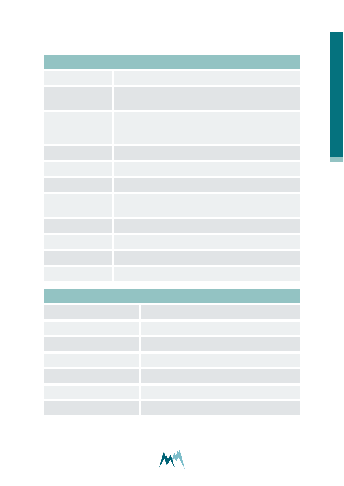
4 Specifications
Physical and environmental
Power supply 6...30 VDC; Reverse voltage protection, overvoltage protection
Power consumption at
12 VDC
Standby approx. 1 mA
Active measurement approx. 110 mA
Outputs RS-485 ASCII / Modbus RTU
SDI-12
Analog output 4…20 mA (14 bit, max. load 250 Ω)
Operating temperature -35…60 °C (-31…140 °F)
Storage temperature -40…60 °C (-40…140 °F)
Protection rating IP 67
Lightning protection Integrated protection against indirect lightning with a discharge capa-
city of 0,6 kW Ppp
Housing material Powder coated aluminum
Mounting bracket Ø34…48 mm
Size L x W x H 241 x 154 x 246 mm (9.49 x 6.06 x 9.69 in)
Weight 2.7 kg (5.95 lb)
Velocity measurement
Detectable measurement range 0.10…15 m/s (depending on the flow conditions)
Accuracy ± 0.01 m/s; ± 1 %
Resolution 1 mm/s
Direction recognition +/-
Measurement duration 5…240 s
Measurement interval 8 s…5 h
Measurement frequency 24 GHz (K-Band)
4 Specifications
Manual 14
Radar opening angle 12°
Distance to water surface 0.50…35 m
Vertical inclination Measured internally
Automatic vertical angle compensation
Accuracy ± 1 °
Resolution ± 0.1 °
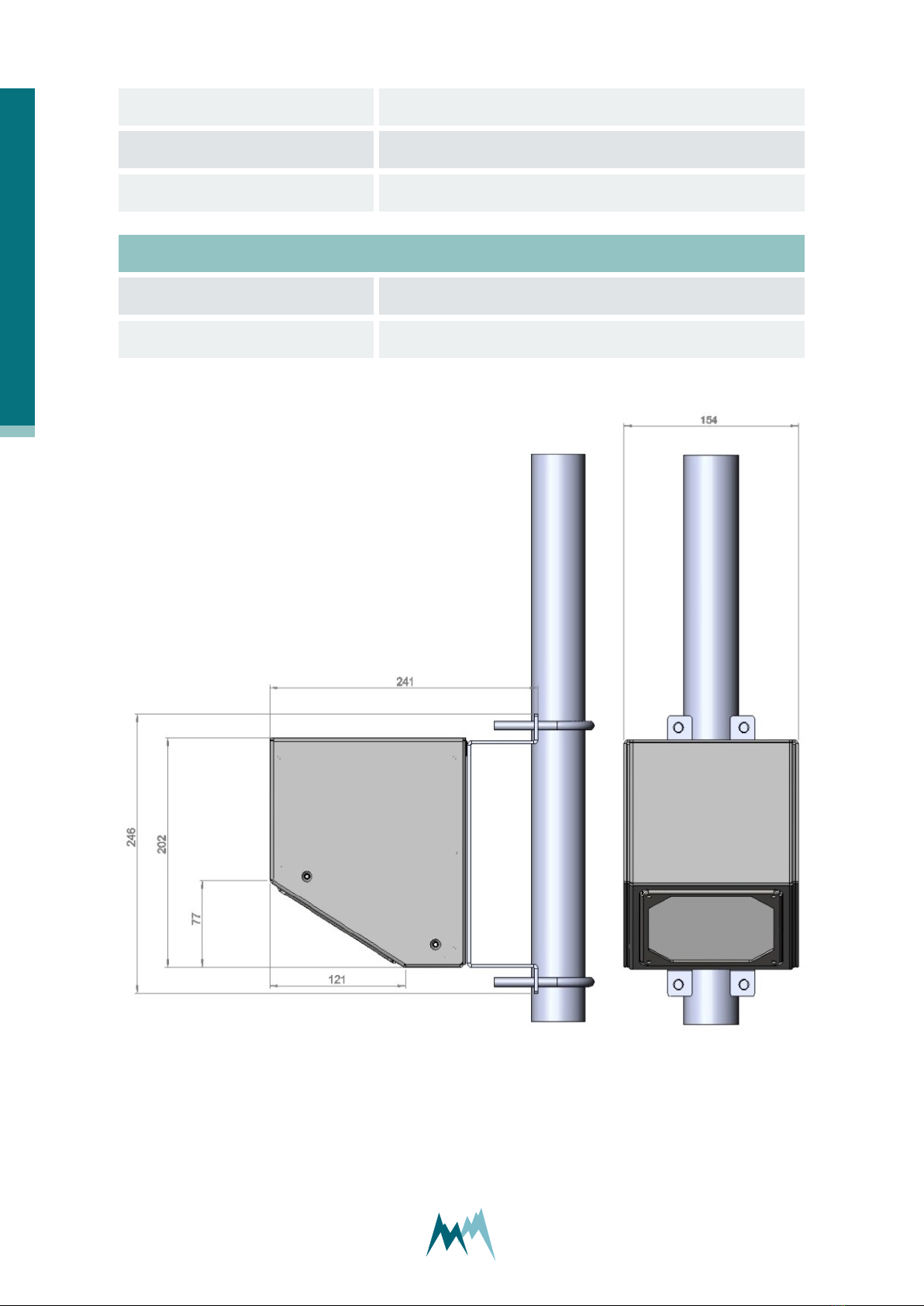
Figure 3 RG-30 dimensions
4 Specifications
15 Manual

5 Connectors
5.1 Main
Figure 4 Pin configuration of connector MAIN
Pin Function Description
Power supply
A GND Ground
B Vsupply +6…+30 V
Trigger input C TRIG low: 0…0.6 V
high: 2…30 V
RS-485 interface
D RS485 A
1 x RS-485 (1200…115200 Baud)
E RS485 B
SDI-12 interface F SDI-12 1 x SDI-12 (1200 Baud)
Switched digital output G DIG-OUT Max. 1.5 A
Analog outputs
(RG-30 a only)
H IOUTGND Analog ground
M IOUT3 Velocity (4…20 mA)
Table 1: Configuration of connector MAIN
5 Connectors
Manual 16

NOTE The analog outputs and the trigger input are referenced to GND on pin
H.
5.2 Connection cable for connector MAIN
The 12-pin connection cable is routed through one of the rubber-sealed holes on the front or back
of the metal housing.
Color Pin Function Description
white A GND Ground
brow B Vsupply 6...30 VDC
green C TRIG low: 0…0.6 V
high: 2…30 V
yellow D RS485 A
1 x RS-485 (1200…115200 Baud)
gray E RS485 B
pink F SDI12 1 x SDI-12 (1200 Baud)
blue G DIG-OUT Max. 1.5 A
red H IOUTGND Ground for analog outputs
blue/red M IOUT3 Velocity
Table 2: Configuration of cable MAIN
5 Connectors
17 Manual

6 How does the RG-30 work?
6.1 Flow velocity
6.1.1 Principle of measurement
The contact-free measurement of the flow velocity is based on the principle of the Doppler Effect.
The integrated velocity radar sensor transmits a signal with a constant frequency in a specific angle
towards the water surface (see Figure 5). There, the signal is reflected and shifted in frequency due
to the movement of the water body. The reflected signal is received by the antenna of the integ-
rated velocity radar sensor. By comparing the emitted frequency to the frequency of the reflected
signal from the water surface the local velocity can be determined.
Figure 5 Principle of flow velocity sensor
6.1.2 Radar spectrum
The integrated velocity radar sensor has an opening angle of 12°. Thus, the reflected radar signal of
an area is measured. The size of this area depends on the inclination angle and the distance
between the sensor and the reflecting water surface.
The velocities appearing in the measured area have a specific distribution depending on the water
flow conditions. The velocity distribution is determined with a digital signal processor via spectral
analysis, and the dominant velocity in the measurement area is calculated.
As illustrated in Figure 6 the radar spectrum is recorded for water flows up- and downstream. In the
lower part of Figure 6 the velocity spectrum of water flowing away from the radar sensor is dis-
6 How does the RG-30 work?
Manual 18
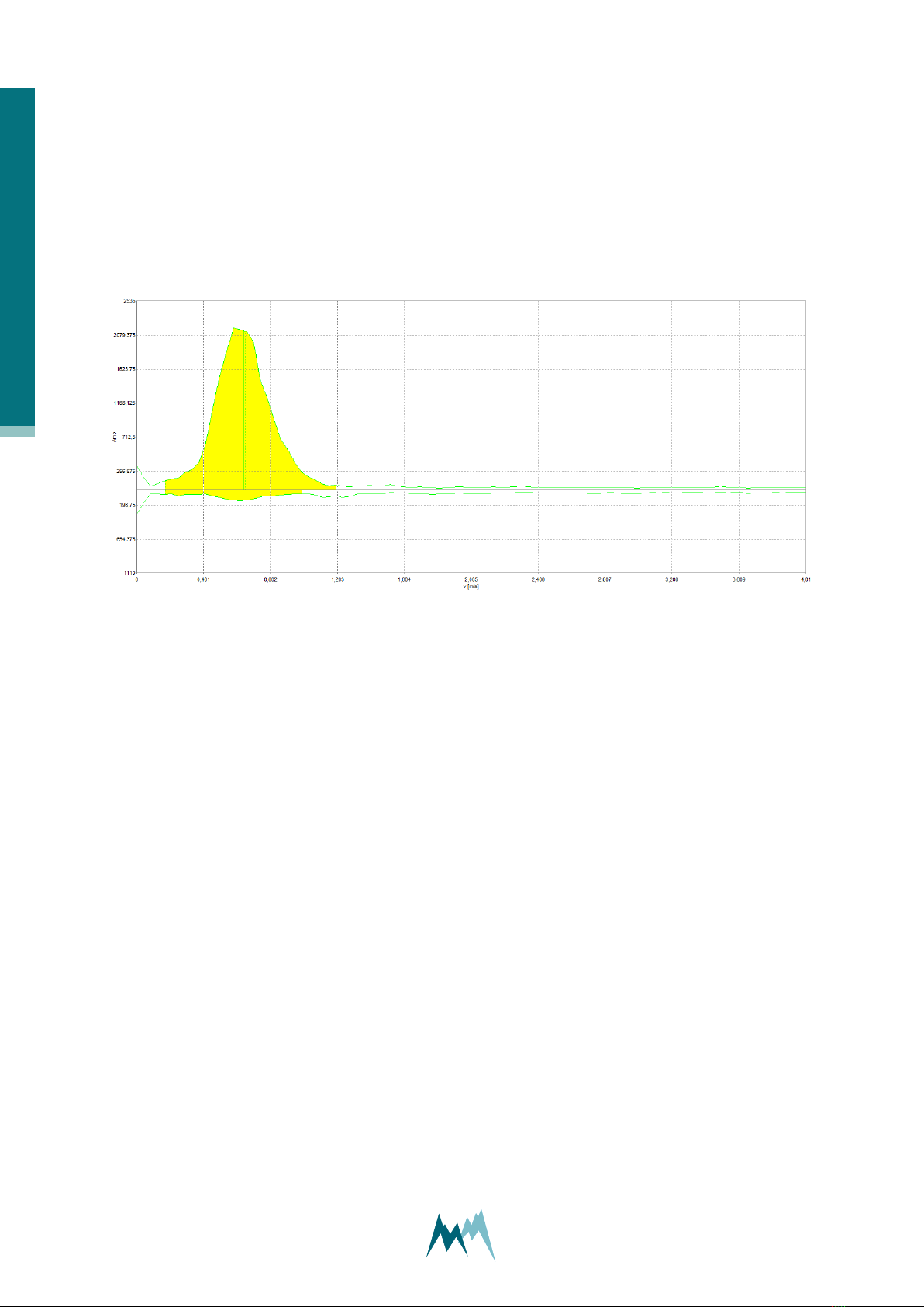
played, in the upper part the spectrum of water flowing towards the sensor. The yellow area is the
part of the spectrum used for analysis and the vertical green line indicates the resulting velocity.
By interpreting the radar spectra, velocity measurements can be analyzed in detail. A spectrum can
have a narrow or broad peak, one or more maxima or it can identify only one velocity direction.
Awareness of this can result in a modification of the settings for the velocity measurement.
For detailed information on how to proceed if more than one peak is visible in the radar spectrum
please refer to Appendix A.
Figure 6 Radar spectrum
6.1.3 Flow direction separation
Water can either flow towards or away from the integrated velocity radar sensor. Depending on the
flow direction a frequency shift to higher or lower frequencies occurs. This circumstance allows the
RG-30 sensor to separate the water movements by their directions and to separately evaluate the
corresponding velocity distribution.
6.1.4 Inclination angle measurement
As the RG-30 sensor is directed in a specific angle towards the water surface an angle correction has
to be applied. The RG-30 measures its vertical inclination with an internal sensor and applies an
automatic angle correction.
6.1.5 Conditions of the water surface
The water surface has to move distinctly and a minimum roughness has to be present to measure a
discernible Doppler frequency shift. The more rippled the water surface and the higher the flow
velocity is the more reliable the measurements are. The minimum ripple height for a valid analysis
6 How does the RG-30 work?
19 Manual

is about 2 mm depending on the used frequency. For very slow moving rivers this requirement
might not be fulfilled and a continuous and correct velocity measurement cannot be guaranteed.
6 How does the RG-30 work?
Manual 20
This manual suits for next models
1
Table of contents
Other SOMMER Measuring Instrument manuals


