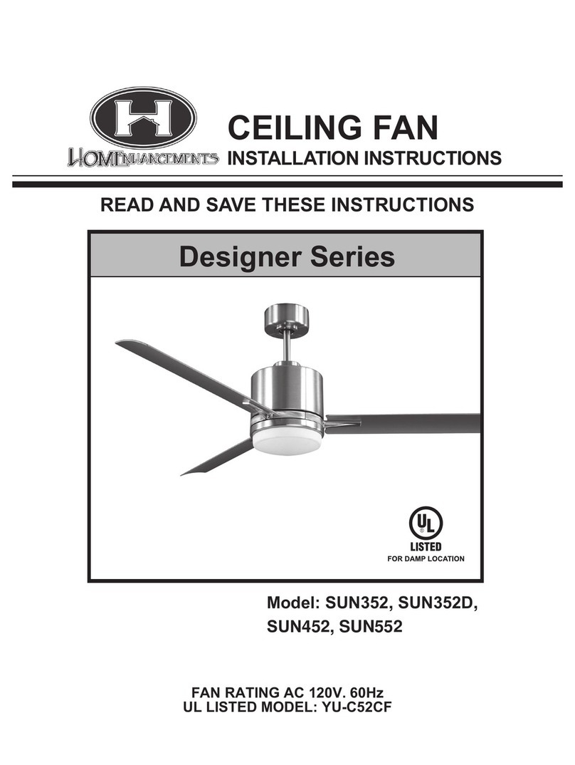
HOMEnhancements SUN866 Series User manual

Please and follow these instructions carefully
SUN866 Series Installation Guide
8-Blade 66" Fan
The following instructions apply to the models below:
SUN866 MB8MB/WL(WC)
SUN866 NK8SV/WL(WC)
SUN866D MB8MB(WC)
SUN866D NK8SV(WC)
Battery MUST be installed , do NOT dispose
*For Calibration, see pg. 9(Very Important)

1
a
b
c
d
e
f
g
h
i
j
o
n
m
l
k
Unpack your fan and check the contents. You
should have the following items:
a. Blade set (8)
b. Hanger bracket
c. Canopy
d. Canopy cover
e. Downrod
f. Coupling cover
g. Fan motor assembly
h. Blade bracket set (8)
i. Mounting plate
j. LED Light kit
k. Glass shade
l. Wall transmitter incl. 2 mounting screws
and 3 wire nuts
m. 2 wall plates (white and almond), 1 face
plate (almond), 2 sets of mounting
screws, and machine screws
n. Battery
o. Package hardware
1) Mounting hardware :
screws (2), washers (2), wire nuts (3)
2) Blade attachment hardware: screws
(25), rubber washers (25)
3) Balance Kit
TOOLS AND MATERIALS REQUIRED
Phillips Screwdriver Stepladder Wire Cutter/Stripper
PARTS INCLUDED

1. To reduce the risk of electric shock, insure
electricity has been turned off at the circuit
breaker or fuse box before beginning.
2. All wiring must be in accordance with the
National Electrical Code and local
electrical codes. Electrical installation
should be performed by a qualified
licensed electrician.
3. CAUTION: Read all instructions and safety
information before installing your new fan.
Review accompanying assembly
diagrams.
4. WARNING: To reduce the risk of personal
injury, use only the two steel screws (and
lock washers) provided with the outlet box
for mounting to the outlet box. Most outlet
boxes commonly used for the support of
lighting fixtures are not acceptable for fan
support and may need to be replaced,
consult a qualified electrician if in doubt.
5. The outlet box and support structure must
be securely mounted and capable of
reliably supporting a minimum of 50
pounds. Use only ETL Listed outlet boxes
marked "FOR FAN SUPPORT".
6. The fan must be mounted with a minimum
of 7 feet clearance from the trailing edge
of the blades to the floor.
7. To operate the reverse function on this fan,
press the reversing button while the fan is
running.
8. Avoid placing objects in the path of the
blades.
9. To avoid personal injury or damage to the
fan and other items, be cautious when
working around or cleaning the fan.
10. Do not use water or detergents when
cleaning the fan or fan blades. A dry dust
cloth or lightly dampened cloth will be
suitable for most cleaning.
11. After marking electrical connections,
spliced conductors should be turned
upward and pushed carefully up into outlet
box. The wires should be spread apart
with the grounded conductor and the
equipment-grounding conductor on one
side of the outlet box.
12. Electrical diagrams are reference only.
Light kit that are not packed with the fan
must be ETL Listed and marked suitable
for use with the model fan you are
installing. Switches must be ETL General
Use Switches. Refer to the Instructions
packaged with the light kits and switches
for proper assembly.
2
SAFETY RULES
WARNING
TO REDUCE THE RISK OF FIRE, ELECTRIC
SHOCK OR PERSONAL INJURY, MOUNT
FAN TO OUTLET BOX MARKED
"ACCEPTABLE FOR FAN SUPPORT".
WARNING
TO REDUCE THE RISK OF PERSONAL
INJURY, DO NOT BEND THE BLADE
BRACKETS (ALSO REFERRED TO AS
FLANGES) DURING ASSEMBLY OR AFTER
INSTALLATION. DO NOT INSERT OBJECTS IN
THE PATH OF THE BLADES.

3
MOUNTING OPTIONS
If there isn't an existing ETL listed mounting
box, then read the following instructions.
Disconnect the power by removing fuses or
turning off circuit breakers.
Secure the outlet box directly to the building
structure. Use appropriate fasteners and
building materials. The outlet box and its
support must be able to fully support the
moving weight of the fan (at least 50 lbs). Do
not use plastic outlet boxes.
Figures 1, 2 and 3 are examples of different
ways to mount the outlet box.
Note: You may need a longer downrod to
maintain proper blade clearance when
installing on a steep, sloped ceiling. (Fig. 3)
To hang your fan where there is an existing
fixture but no ceiling joist, you may need an
installation hanger bar as shown in Figure 4.
Outlet box
Provide strong
support
Recessed
outlet box
Outlet box
Figure 1
Figure 3
Figure 4
Outlet box
Figure 2
Ceiling
hanger
bracket
ANGLED CEILING
MAXIMUM 20° ANGLE

Figure 7
Registration slot
4
Figure 5
Figure 6
Downrod
Canopy
Set screws
Locking
pin
Hanger pin
Canopy cover
Coupling cover
Step 1. Hanging the Motor
REMEMBER to turn off the power. It is
recommended to flip the breaker and check
for power with a multi-meter before
continuing. Follow the steps below to hang
your fan properly:
1. Pass the 120-volt supply wires
through the center hole in the ceiling hanger
bracket as shown in Fig. 5.
2. Secure the hanger bracket to the
ceiling outlet box with the screws
and washers provided with your outlet box.
3. Remove the hanger pin, locking pin
and set screws from the top of the
motor assembly.
4. Route wires exiting from the top of
the fan motor through the couping
cover, canopy cover and canopy, then
through the ball / downrod. (Fig. 6)
5. Align the holes at the bottom of
the downrod with the holes in the collar on
top of the motor housing (Fig. 6). Carefully
insert the hanger pin through the holes in the
collar and downrod. Be careful not to jam
the pin against the wiring inside the
downrod. Insert the locking pin through the
hole near the end of the hanger pin until it
snaps into its locked position. (Fig. 6)
6. Tighten two set screws on top of the fan
motor firmly. (Fig. 6)
7. Place the downrod ball into the
hanger bracket socket. (Fig. 7)
8. Rotate the downrod until the downrod
ball falls into place with the socket. This is
necessary to prevent the fan from moving
during operation.
ETL Listed
electrial
box
Ceiling
hanger
bracket
Mounting screws
(supplied with
electrical box)
120V Wires
Washers

5
Step 2. Starting to Wire Motor
WARNING: To avoid possible electrical
shock, be sure electricity is turned off at the
main fuse box before wiring.
Use the wire nuts supplied with your fan
when making connections. Secure the
connectors with electrical tape and make
sure there are no loose connections or wire
strands.
Step 1. Spread the wires apart so that the
black wire from the fan is on one side of the
mounting bracket and the white wire and
green ground wire are on the other side.
Step 2. (Fig. 8) Connect the BLACK building
supply wire to the BLACK fan wire. Connect
the WHITE building neutral wire to the
WHITE fan neutral wire. Connect the
COPPER building ground wire to the GREEN
fan ground wire.
Step 3. Inside the ceiling junction box be sure
to spread the wires apart so that the black
connection is on one side of the outlet box
and the white/white and green/copper
connections are on the other side.
Step 4. Connect the wiring from the wall
switch receptacle to wall transmitter unit.
● Remove the existing wall plate and switch
from the wall junction box.
● Connect one BLACK wire from the wall to
one BLACK wire (labeled "TO FAN") from the
wall transmitter.
● Connect the other BLACK wire (labeled
"TO POWER SUPPLY") from the transmitter
to the remaining BLACK wire from the wall
(A/C supply source).
● If your junction box has a ground wire
(green or bare copper), connect the
transmitter's ground wire to it. Otherwise,
connect the transmitter ground wire directly to
one of the screws from the outlet box.
● Carefully tuck the connected wires inside
the junction box. Secure the transmitter with
the two screws provided. Attach the face
plate over the transmitter with the two screws
provided.
Step 5. Inside the ceiling junction box be sure
to spread the wires apart so that the black
connection is on one side of the outlet box
and the white/white and green/copper
connections are on the other side.
Figure 8
Fan
Wall control
SUPPLY CIRCUIT
BLACK
BLACK
BLACK BLACK
Ground
Conductor
Outlet Box
Green Ground
Lead
Ground to
Downrod
GREEN
WHITE WHITE

6
1. Tuck connections neatly into ceiling outlet box.
2. Slide the canopy up to hanger bracket and place the key
hole on the canopy over the screw on the hanger bracket,
turn canopy until it locks in place at the narrow section of
the key holes. (Fig. 9)
3. Align the circular hole on canopy with the remaining hole
on the hanger bracket, secure by tightening the two
set screws. Note: Adjust the canopy screws as necessary
until the canopy and canopy cover are snug.
WARNING: Make sure tab at bottom of hanger
bracket is properly seated in groove of hanger ball before
attaching canopy to bracket. Failure to properly seat tab in
groove could cause damage to electrical wiring.
Figure 9
Figure 10
Outlet box
Hanger
bracket
Canopy
Canopy cover
Screws
Step 4. Attaching the Blades
CAUTION: Remove 5 rubber packing mounts
and discard before installation.
1. Attach the blade to the blade bracket
using the screws and rubber washers as
shown in Figure 10. Start screw into bracket,
do not tighten. Repeat for the two remaining
screws.
2. Tighten each screw. Make sure the
blade is straight.
3. Fasten blade assembly to motor using the
screws supplied. (Fig. 10) Screws
Blade
Blades bracket
Screws and
rubber washers
Step 3. Finishing the Motor Connection

7
Step 6. Wiring the Light Kit
NOTE: Before starting installation, disconnect
the power by turning off the circuit breaker or
removing the fuse at fuse box. Turning power
off using the fan switch is not sufficient to
prevent electric shock.
1. Remove the 1 of 3 screws from the
mounting plate and loosen the other 2
screws. (Do not remove)
2. Raise and hold the LED light kit close to
the mounting plate and proceed to do the
wire connections. Connect the white wire
connectors from the light kit and fan, follow
the same procedure with the black wire
connectors. (Fig. 12)
3. Place the key holes on the light kit over
the 2 screws previously loosened from the
mounting plate, turn light kit until it locks in
place at the narrow section of the key
holes. Secure by tightening the 2 screws
previously loosened and the one previously
removed.
4. Install the glass shade over the light kit,
gently turn until it locks into place and is
firm; DO NOT OVER TIGHTEN.
Figure 12
Figure 11
Step 5. Attaching the LED Mounting Plate
1. Remove the 1 of 3 screws from the
mounting ring and keep it for future use.
Loosen the other 2 screws. (Do not remove)
2. Place the key holes on the mounting
plate over the 2 screws previously loosened
from the mounting ring, turn mounting plate
until it locks in place at the narrow section of
the key holes. Secure by tightening the 2
screws previously loosened and the one
previously removed. (Figure 11)
Screw
Mounting plate
Mounting ring
Mounting plate
Screws
LED light kit
Wire connection plugs
Glass shade

8
Figure 13
Step 7. Wiring the Wall Control
WARNING: Do NOT connect the neutral
(white) wire in the wall control junction box to
the wall control. Doing so will fry the electrical
components of the wall control. Only wire the
two hot (black) wires in the wall to the wall
control.
1. Remove the existing wall plate and
switch from the wall junction box.
2. If your outlet box has a ground wire
(green or bare copper) connect the wall
control's ground wire to it; otherwise connect
the wall control's ground wire directly to one
of the screws from the outlet box.
3. (Fig. 13) Carefully tuck the wire
connections inside the junction box. Secure
the wall control with the two screws provided.
Attach the wall plate over the wall control and
secure with the two screws provided.

9
Figure 14
Figure 15
Step 8. Fan Calibration
The SUN866 Series of HOMEnhancements
DC Motor fans has a smart receiver built into
the motor's housing. During calibration of the
wall control, the wall control will automatically
be detected by the built in receiver when
wired on the same circuit and with a battery
installed. These receivers should be pre-
calibrated with the included wall control, but
recalibration may be necessary. Recalibration
steps will be elaborated on below.
Remove the panel from the transmitter and
then install one 23A/12V battery (included).
This fan REQUIRES this battery to be
installed to function correctly.
A. I, II, III, IV, V and VI buttons: (Fig. 15).
These six buttons are used to set the fan
speed as follows:
I = slowest speed
II = low speed
III = medium low speed
IV = medium speed
V = medium high speed
VI = fastest speed
B. b Button:
This button turns the fan off.
C. Reverse button:
This button is to control fan direction.
D. Light button:
This button is to control optional light. Switch
the "D" and "ON" dip switch on the front of
transmitter to decide the light in "ON/OFF" or
"Dimmable" condition.
E. "SET" code setting button:
Follow the steps under "Pairing Process" to
use the set button.
F. ON - OFF Slide button: Keep in the "ON"
position.
Pairing Process (Very Important)
After installing the unit and restoring
power to the fan, press and hold the
“SET” button for 5 seconds. You must do
this within 60 seconds of turning the
power slider on the bottom of the wall
control from “OFF” to “ON”. If optional
light kit is installed, the light kit will flash twice
and the signal light on the wall control will
come on when the button is pressed.
The fan has completed the pairing process
with the wall control and is ready for use.
If installed in a vacation home or an area where
you intend to not use the fan for months at a
time, make sure to remove and reinsert the
battery upon returning to prevent battery
leakage that could harm the wall control
components.

10
Pairing Process for Multiple Fans:
Select the desired frequency setting from the
back of the remote control. (Fig 14) You
change the frequency setting by arranging
the small switches numbered 1 through 4
in the up or down position making 16
different frequencies or combinations
possible. Anytime you change the
frequency for a fan you must complete the
pairing process as described above.
Beginning with the power off to all fans,
restore power to the first fan. Select the
desired frequency setting. Complete
the pairing process as described above.
Test the fan for proper operation. Then
power off and move to the next fan.
Restore power to the second fan. Select the
desired frequency setting. Complete
the pairing process as described above.
Test the fan for proper operation.
Repeat this process until all fans have been
paired.
The receiver provides the following
protective function:
1. Lock position: The DC motor has a
built-in safety against obstruction during
operation. The motor will be locked operation
and disconnect power after 30
seconds of interruption. Please remove
obstacles before re-set.
2. Over 80W protection: When the receiver
detects motor power consumption which is
greater than 80W, the receiver power will be
stopped and operation will immediately
discontinue. Turn the receiver power on after
5 seconds.
Speed settings for warm or cool weather
depend on factors such as the room size,
ceiling height, number of fans, and so on.
NOTE: To operate the reverse function on
this fan, press the reverse button while the
fan is running.
Warm weather - (Forward) A downward air
flow creates a cooling effect as shown in
Figure 16. This allows you to set your air
conditioner on a higher setting
without affecting your comfort.
Cool weather - (Reverse) An upward airflow
moves warm air off the ceiling area as shown
in Figure 17. This allows you to set your
heating unit on a lower setting
without affecting your comfort.
Figure 16
Figure 17

11
1. Because of the fan's natural movement, some connections may become loose. Check the
support connections, brackets, and blade attachments twice a year. Make sure they are secure
(It is not necessary to remove the fan from the ceiling.)
2. Clean your fan periodically to help maintain its new appearance over the years. Use only a
soft brush or lint-free cloth to avoid scratching the finish. The plating is sealed with a lacquer to
minimize discoloration or tarnishing. Do not use water when cleaning. This could damage the
motor, or the wood, or possibly cause an electrical shock.
3. There is no need to oil your fan. The motor has permanently lubricated bearings.
FAN MAINTENANCE
Here are some suggestions to help you maintain your fan
IMPORTANT
MAKE SURE THE POWER IS OFF AT THE ELECTRICAL PANEL BOX BEFORE YOU
ATTEMPT ANY REPAIRS. REFER TO THE SECTION "MAKING ELECTRICAL
CONNECTIONS".

12
TROUBLESHOOTING GUIDE
Not working or Turns on/off on its own:
•Please install blades first before turning on fan(Fan will not work if blades are not installed)
•Check Wall control battery (red LED will light up if battery is good and installed correctly).
•Make sure that wires are not pinched anywhere in the canopy.
•Check House breaker box.
•Make sure all wire connections have enough exposed wire before twisting together to ensure a strong connection.
•Switch Dip switches to a new configuration and hold down “SET” for five seconds to apply settings and blades
will swivel back and fourth please allow fan to spin for at least 5 minutes to complete calibration
•Fan will Not work on a 3-way switch
If multiple SUN866 fans are owned, make sure the dip switches are set todifferent channels. All other SUN866 models
must be powered off when syncing each fan.
Please refer to the following QR code to ensure fans are properly synced and calibrated:
Noisy/Wobble:
Other:
•Make sure the blade screws, light kit screws, andfan bracket/electrical box screws are tightened.
•Make sure wire nut connections are not rubbing inside housing.
•Do not connect fan with a wall mounted variable speed control.
•Use provided balance kit to ensure that all blades are level, allow for an1/8” deviation.
•If blades still wobble interchange two adjacent blades.
•Lock position: Motor will lock and disconnect from power after 30 seconds of interruption.
•Over 80w protection:When the receiver detects motor power consumption of 80w or greater the receiver will be stopped,
and operationwill stop.Turn the receiver power on after 5 seconds.
•If using the handheld remote, the dipswitches within the wall control and the handheld remote need tobe set tothe same
settings and both will operate the fan simultaneously. The last dip switch on the wall control isthe dimming switch.

Por favor, lee y sigue estas instrucciones
cuidadosamente.
Guía de instalación de la serie
SUN866
8-Blade 66" Ventilador
Las siguientes instrucciones se aplican a los modelos que se
detallan a continuación:
SUN866 MB8MB/WL(WC)
SUN866 NK8SV/WL(WC)
SUN866D MB8MB(WC)
SUN866D NK8SV(WC)
La batería DEBE ser instalada, NO desechar

1
a
b
c
d
e
f
g
h
i
j
o
n
m
l
k
Desempaca tu ventilador y verifica el
contenido. Deberías tener los siguientes
elementos:
a. Conjunto de aspas (8)
b. Soporte colgante
c. Dosel
d. Cubierta del dosel
e. Varilla de extensión
f. Cubierta de acoplamiento
g. Conjunto de motor del ventilador
h. Conjunto de soportes de aspas (8)
i. Placa de montaje
j. Kit de luz LED
k. Pantalla de vidrio
l. Transmisor de pared incluido con 2
tornillos de montaje y 3 tuercas de cable
m. 2 placas de pared (blanca y almendra), 1
placa frontal (almendra), 2 juegos de
tornillos de montaje y tornillos de máquina
n. Batería
o. Herrajes del paquete
1) Herrajes de montaje:
tornillos (2), arandelas (2), tuercas de
cable (3)
2) Herrajes de fijación de las aspas:
tornillos (25), arandelas de goma (25)
3) Kit de equilibrado
HERRAMIENTAS Y MATERIALES REQUERIDOS
Destornillador Phillips Escalera Cortador/pelacables
PARTES
INCLUIDOS

1. 1. Para reducir el riesgo de descarga eléctrica,
asegúrese de que se haya apagado la
electricidad en el disyuntor o en la caja de
fusibles antes de comenzar.
2. 2. Todo el cableado debe estar de acuerdo con
el Código Eléctrico Nacional y los códigos
eléctricos locales. La instalación eléctrica debe
ser realizada por un electricista calificado.
3. 3. PRECAUCIÓN: Lea todas las instrucciones
e información de seguridad antes de instalar su
nuevo ventilador. Revise los diagramas de
montaje adjuntos.
4. 4. ADVERTENCIA: Para reducir el riesgo de
lesiones personales, use solo los dos tornillos
de acero (y arandelas de seguridad) provistos
con la caja de salida para montar en la caja de
salida. La mayoría de las cajas de
tomacorrientes que se usan comúnmente para
el soporte de los artefactos de iluminación no
son aceptables para el soporte del ventilador y
es posible que deban reemplazarse; consulte a
un electricista calificado en caso de duda.
5. 5. La caja de distribución y la estructura de
soporte deben estar montadas de manera
segura y ser capaces de soportar de manera
confiable un mínimo de 50 libras. Utilice
únicamente cajas de salida con certificación UL
marcadas como "PARA SOPORTE DE
VENTILADORES".
6. 6. El ventilador debe montarse con un mínimo
de 7 pies de espacio libre desde el borde de
salida de las aspas hasta el piso.
7. 7. No opere el interruptor de marcha atrás
mientras las aspas del ventilador estén en
movimiento. El ventilador debe estar apagado y
las aspas detenidas antes de invertir la
dirección de las aspas.
8. 8. Evite colocar objetos en el camino de las
palas.
9. 9. Para evitar lesiones personales o daños al
ventilador y otros elementos, tenga cuidado
cuando trabaje alrededor o limpie el ventilador.
10. 10. No use agua ni detergentes para limpiar el
ventilador o las aspas del ventilador. Un paño
seco para el polvo o un paño ligeramente
humedecido será adecuado para la mayoría de
las limpiezas.
11. 11. Después de marcar las conexiones
eléctricas, los conductores empalmados deben
girarse hacia arriba y empujarse con cuidado
hacia arriba en la caja de distribución. Los
cables deben separarse con el conductor
conectado a tierra y el conductor de conexión a
tierra del equipo en un lado de la caja de salida.
12. 12. Los diagramas eléctricos son solo de
referencia. El juego de luces que no viene
incluido con el ventilador debe estar listado por
CUL y marcado como adecuado para su uso
con el modelo de ventilador que está
instalando. Los interruptores deben ser
interruptores de uso general CUL. Consulte las
instrucciones empaquetadas con los kits de
luces e interruptores para un montaje
adecuado.
2
3. REGLAS DE SEGURIDAD
ADVERTENCIA
PARA REDUCIR EL RIESGO DE INCENDIO,
DESCARGA ELÉCTRICA O LESIONES PERSONALES,
MONTE EL VENTILADOR EN LA CAJA DE TOMAS
MARCADA
"ACEPTABLE PARA SOPORTE DE VENTILADORES".
ADVERTENCIA
PARA REDUCIR EL RIESGO DE LESIONES
PERSONALES, NO DOBLE LOS SOPORTES DE LAS
HOJAS (TAMBIÉN REFERIDOS COMO BRIDAS)
DURANTE EL MONTAJE O DESPUÉS DE LA
INSTALACIÓN. NO INTRODUZCA OBJETOS EN EL
CAMINO DE LAS CUCHILLAS.

3
4. OPCIONES DE MONTAJE
Si no existe una caja de montaje listada por UL, lea
las siguientes instrucciones. Desconecte la energía
quitando los fusibles o apagando los disyuntores.
Asegure la caja de distribución directamente a la
estructura del edificio. Utilice sujetadores y
materiales de construcción adecuados. La caja de
salida y su soporte deben poder soportar
completamente el peso en movimiento del
ventilador (al menos 50 libras). No utilice cajas de
salida de plástico.
Las figuras 1, 2 y 3 son ejemplos de diferentes
formas de montar la caja de salida.
Nota: Es posible que necesite una varilla más larga
para mantener la separación adecuada de la hoja
al instalar en un cielo raso empinado e inclinado.
(Fig. 3)
Para colgar su ventilador donde hay un accesorio
existente pero no una viga de techo, es posible
que necesite una barra de suspensión de
instalación como se muestra en la Figura 4.
Caja de salida
Brindar un fuerte apoyo
Caja de salida
empotrada
Caja de salida
Figura1
Figura3
Figura4
Caja de salida
Figura2
Soporte de hangar de techo

Figura7
Ranura de registro
4
Soporte de hangar
de techo
Tornillos de montaje (suministrados
con la caja eléctrica)
Gancho
Caja eléctrica con
certificación UL
Figura5
120V Alambres
Arandelas
Figura6
Varilla
Pabellón
Tornillos de fijación
Pin de seguridad
Pasador de
suspensión
Cubierta del dosel
Tapa de acoplamiento
5. COLGAR EL VENTILADOR
RECUERDA apagar la energía. Siga los pasos a
continuación para colgar su ventilador
correctamente:
Paso 1. Pase los cables de suministro de 120
voltios a través del orificio central en el soporte de
suspensión del techo como se muestra en la Fig.5.
Paso 2. Asegure el soporte de suspensión a la caja
de salida del techo con los tornillos y arandelas
provistos con su caja de salida.
Paso 3. Retire el pasador de suspensión, el pasador
de bloqueo y los tornillos de fijación de la parte
superior del conjunto del motor.
Paso 4. Enrute los cables que salen de la parte
superior del motor del ventilador a través de la
cubierta del acople, la cubierta del toldo y el toldo,
luego a través de la bola / varilla. (Figura 6)
Paso 5. Alinee los orificios en la parte inferior de la
varilla con los orificios en el collar en la parte
superior de la carcasa del motor (Fig. 6). Inserte con
cuidado el pasador de suspensión a través de los
orificios del collar y la varilla. Tenga cuidado de no
atascar el pasador contra el cableado dentro de la
varilla. Inserte el pasador de bloqueo a través del
orificio cerca del extremo del pasador de
suspensión hasta que encaje en su posición
bloqueada, como se indica en el recuadro circular
de la Fig.6.
Paso 6. Apriete firmemente dos tornillos de fijación
en la parte superior del motor del ventilador. (Figura
6)
Paso 7. Coloque la bola de la varilla en el
receptáculo del soporte de suspensión. (Figura 7)

5
6. REALIZAR LAS CONEXIONES ELÉCTRICAS
ADVERTENCIA: Para evitar posibles descargas
eléctricas, asegúrese de que la electricidad esté
apagada en la caja de fusibles principal.
antes del cableado.
Utilice las tuercas para cables suministradas con
su ventilador al realizar las conexiones. Asegure
los conectores con cinta aislante y asegúrese de
que no haya conexiones sueltas o hilos de
alambre.
Paso 1. Separe los cables de modo que el cable
negro del ventilador esté en un lado del soporte de
montaje y el cable blanco y el cable de tierra verde
estén en el otro lado.
Paso 2. (Fig. 8) Conecte el cable NEGRO de
suministro del edificio al cable NEGRO del
ventilador. Conecte el cable neutro BLANCO del
edificio al cable neutro BLANCO del ventilador.
Conecte el cable de tierra del edificio de COBRE al
cable de tierra VERDE del ventilador.
Paso 3. Dentro de la caja de conexiones del techo,
asegúrese de separar los cables de modo que la
conexión negra esté en un lado de la caja de salida
y las conexiones blanco / blanco y verde / cobre
estén en el otro lado.
Paso 4. Conecte el cableado desde el receptáculo
del interruptor de pared a la unidad transmisora de
pared.
●Retire la placa de pared existente y cambie de la
caja de conexiones de pared.
●● Conecte un cable NEGRO de la pared a un
cable NEGRO (etiquetado "TO FAN") del
transmisor de pared.
●Conecte el otro cable NEGRO (etiquetado "A LA
FUENTE DE ALIMENTACIÓN") del transmisor al
cable NEGRO restante de la pared (fuente de
suministro de A / C).
●Si su caja de conexiones tiene un cable de tierra
(verde o cobre desnudo), conecte el cable de tierra
del transmisor a él. De lo contrario, conecte el cable
de tierra del transmisor directamente a uno de los
tornillos de la caja de salida.
●Meta con cuidado los cables conectados dentro
de la caja de conexiones. Asegure el transmisor
con los dos tornillos proporcionados. Fije la placa
frontal sobre el transmisor con los dos tornillos
proporcionados.
Paso 5. Dentro de la caja de conexiones del techo,
asegúrese de separar los cables de modo que la
conexión negra esté en un lado de la caja de salida
y las conexiones blanco / blanco y verde / cobre
estén en el otro lado.
Figura8
Ventilador de techo
Control de pared
SUPPLY CIRCUIT
NEGRO
NEGRO
NEGRO NEGRO
Conductor de tierra
Caja de salida
Cable de tierra verde
Tierra a Downrod
AZUL
BLANCO BLANCO

6
7. TERMINANDO EL INSTALACIÓN
Paso 1. Meta las conexiones cuidadosamente en la caja
de salida del techo.
Paso 2. Deslice el dosel hasta el soporte de suspensión y
coloque el orificio de la cerradura en el toldo sobre el
tornillo en el soporte de suspensión, gire el toldo hasta que
encaje en su lugar en la sección estrecha de los orificios
de la cerradura. (Figura 9)
Paso 3. Alinee el orificio circular en el dosel con el orificio
restante en el soporte de suspensión, asegure apretando
los dos tornillos de fijación. Nota: Ajuste los tornillos de la
capota según sea necesario hasta que la capota y la
cubierta de la capota estén ajustadas.
ADVERTENCIA: Asegúrese de que la lengüeta en la parte
inferior del soporte de suspensión esté asentada
correctamente en la ranura de la bola de suspensión antes
de colocar la capota en el soporte. No asentar
correctamente la lengüeta en la ranura podría dañar el
cableado eléctrico.
Figura9
Figura10
Caja de salida
Soporte de
suspensión
Pabellón
Cubierta del dosel
Tornillos de manos
Empulgueras
Espada
Soporte de cuchillas
Empulgueras
8. COLOCACIÓN DE LAS HOJAS DEL
VENTILADOR
Paso 1. Fije la hoja al soporte de la hoja usando
los tornillos como se muestra en la Figura 10.
Empiece a atornillar el soporte. Repita para los tres
tornillos restantes.
Paso 2. Apriete cada tornillo. Asegúrese de que la
hoja esté recta.
Paso 3. Fije el conjunto de cuchillas al motor con
los tornillos suministrados. (Figura 10)
This manual suits for next models
4
Table of contents
Languages:
Other HOMEnhancements Fan manuals
Popular Fan manuals by other brands

Helios
Helios M1/100 N/C Installation and operating instructions for

El Corte Inglés
El Corte Inglés VP-214S manual

CFM
CFM 167219 Brochure & specs

Xpelair
Xpelair LVCF20 Installation and maintenance instructions

Trox Technik
Trox Technik X-GRILLE modular installation manual

Hunter Pacific
Hunter Pacific Majestic Rosewood installation manual