Homentry HE60ANZ User manual

www.homentry.com.au
HE60ANZ
Garage Door Opener
Installation and Operating Instructions
Owners Copy: lease keep these instructions for future reference
This manual contains IM ORTANT SAFETY information.
DO NOT ROCEED WITH THE INSTALLATION BEFORE READING THOROUGHLY.


1
CONTENTS AGE
SAFETY INSTRUCTIONS . . . . . . . . . . . . . . .1
DOORTYPES ........................2
TOOLSREQUIRED ....................2
HARDWARE PROVIDED . . . . . . . . . . . . . . . .2
BEFOREYOUBEGIN ..................3
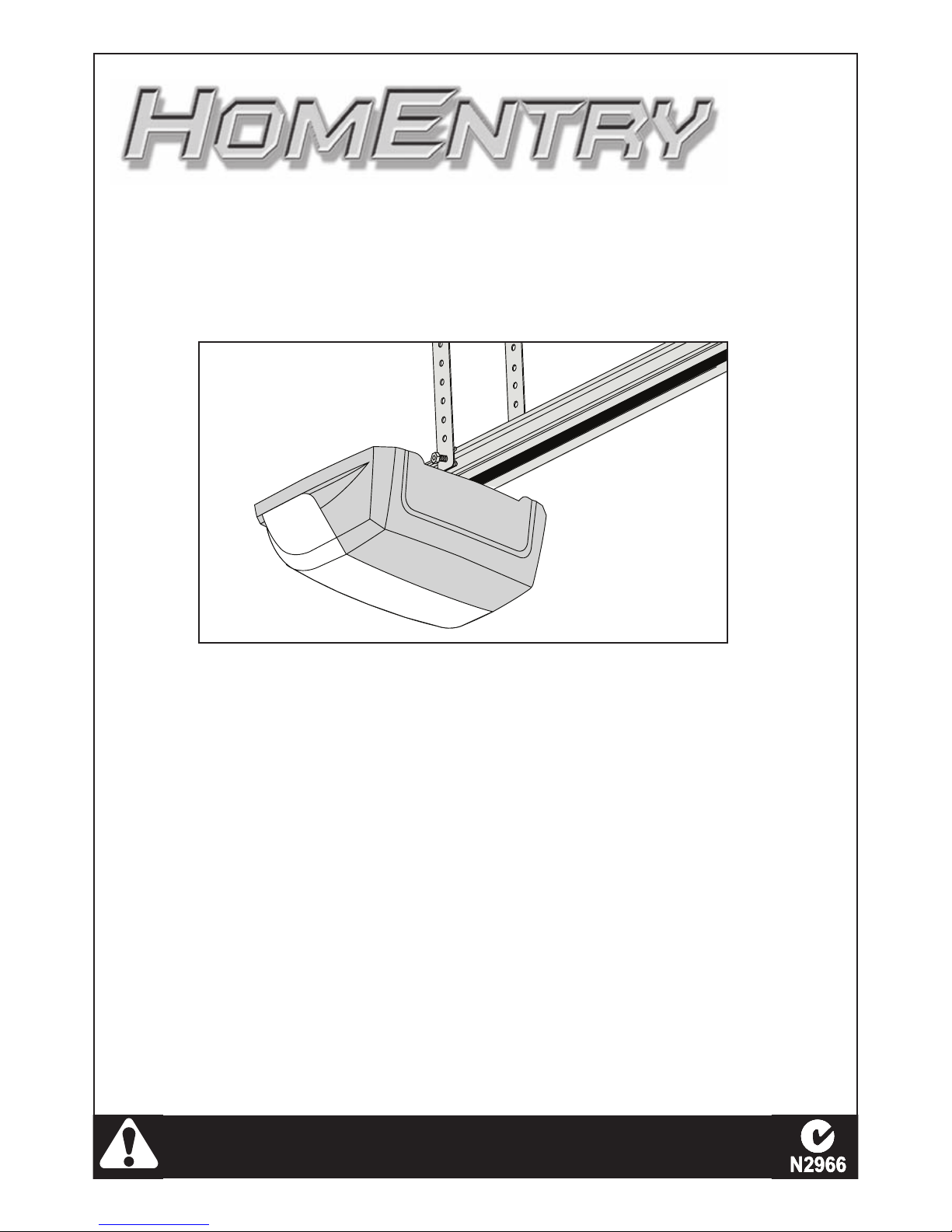
COMPLETED INSTALLATION . . . . . . . . . . . .3
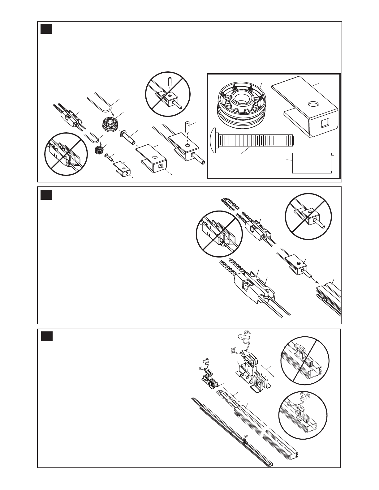
ASSEMBLY .........................3-5
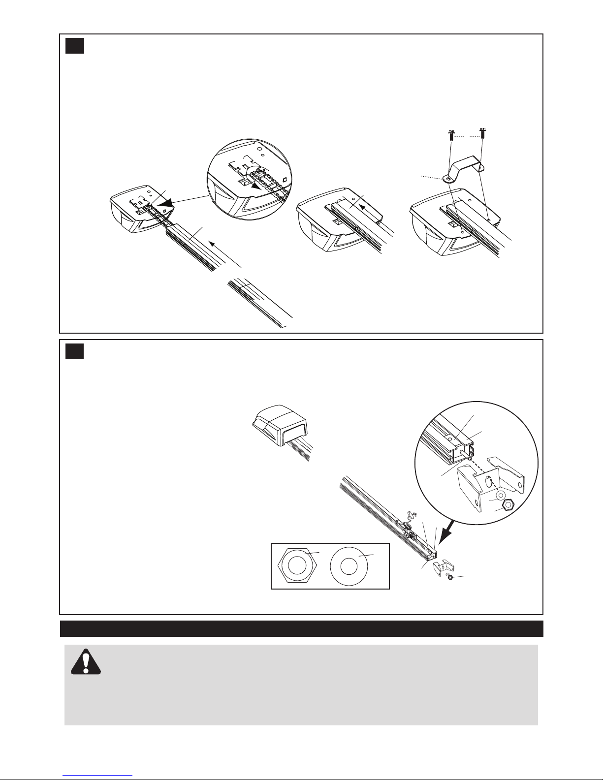
INSTALLATION ......................5-8
CONNECT ELECTRIC POWER . . . . . . . . . .8
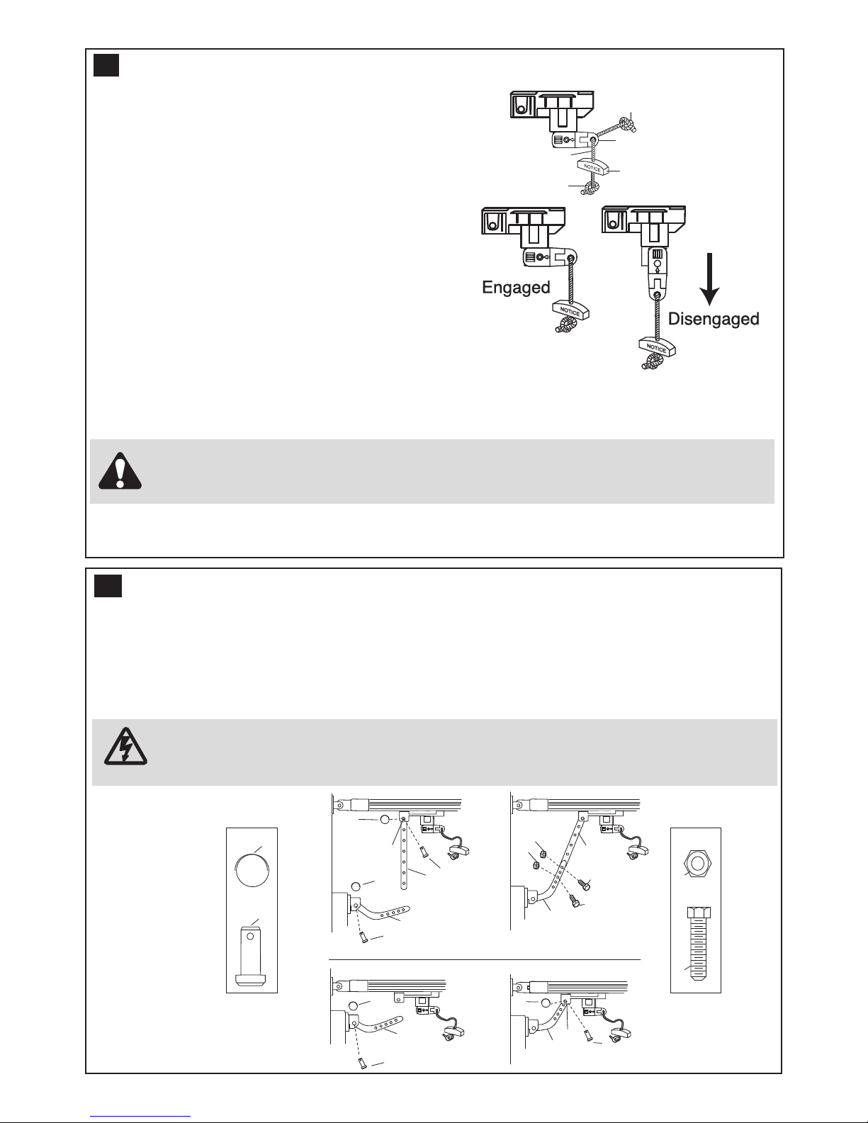
AD USTMENT ........................9
INSTALL PROTECTOR SYSTEM . . . . . . . .10
WIRELESS PROGRAMMING . . . . . . . . .11-12
INSTALL DOOR CONTROL . . . . . . . . . . . . .13
ACCESSORIES ......................14
REPLACEMENT PARTS . . . . . . . . . . . . . . .14
OPERATION OF YOUR OPENER . . . . . . . .15
CARE OF YOUR OPENER . . . . . . . . . . . . .15
MAINTAENANCE OF YOUR OPENER . . . 15
TROUBLE SHOOTING . . . . . . . . . . . . . . . .16
SPECIFICATIONS ....................16
WARRANTY .........................17
NOTE: If your garage has no service entrance door, a AML1702 outside quick release must be installed.
This accessory allows manual operation of the garage door from outside in case of power failure.
WARNING
• Failure to comply with the following instructions may result in serious personal injury or property damage.
• Read and follow all instructions carefully.
• The garage door opener is designed and tested to offer safe service provided it is installed and
operated in strict accordance with the instructions in this manual.
These safety alert symbols mean WARNING : A possible risk to personal safety or
property damage exists.
START BY READING THESE IMP RTANT SAFETY INSTRUCTI NS
The Protector SystemTM must be used for all
installations where the closing force as meas-
ured on the bottom of the door is over 400N
(40kgf). Excessive force will interfere with the prop-
er operation of the Safety Reverse System or dam-
age the garage door.
After installation, ensure that the parts of the
door do not extend over public footpaths or
roads.
Install the wireless wall control (or any additional
wall control) in a location where the garage door
is visible, at a height of at least 1.5m and out of
the reach of children. Do not allow children to
operate push button(s) or transmitter(s). Serious
personal injury from a closing garage door may
result from misuse of the opener.
Permanently fasten the Warning Labels in
Prominent Places, adjacent to Wall Controls and
manual release mechanisms as a reminder of safe
operating procedures.
Activate opener only when the door is in full
view, free of obstructions and the opener is
properly adjusted. No one should enter or leave
the garage while the door is in motion.
Do not allow children to play near the door, or
door controls.
Disconnect electric power to the garage door
opener before making repairs or removing cov-
ers.
KEEP THESE INSTRUCTI NS
Keep garage door balanced.Do not let the
garage door opener compensate for a binding or
sticking garage door. Sticking, binding or unbal-
anced doors must be repaired before installing this
opener.
Do not wear rings, watches or loose clothing
while installing or servicing a garage door opener.
Frequently examine the door installation, in par-
ticular cable, springs and mountings for signs of
wear, damage or imbalance. Do not use if repair or
adjustment is needed since springs and hardware
are under extreme tension and a fault can cause
serious personal injury.
To avoid serious personal injury from entangle-
ment, remove all ropes, chains and locks con-
nected to the garage door before installing the
door opener.
Installation and wiring must be in compliance with
your local building and electrical codes.
The safety reverse system test is very impor-
tant. Your garage door MUST reverse on contact
with a 40mm obstacle placed on the floor. Failure to
properly adjust the opener may result in serious
personal injury from a closing garage door. Repeat
the test once a month and make any necessary
adjustments.
This opener should not be installed in a damp
or wet space exposed to weather.
This appliance is not intended for use by persons
(including children) with reduced physical, sensory
or mental capabilities, or lack of experience and
knowledge, unless they have been given supervi-
sion or instruction concerning use of the appliance
by a person responsible for their safety.

2
AB
A. Sectional Door with
Curved Track
B. One-Piece Door with
Horizontal Track Only
Max door height : 2.125m
Max door width : 3.5m
NOTE: Unit will not work
with One- iece Doors with-
out Horizontal and Vertical
Tracks, Double-Wing
Doors, or Canopy Doors.
1D R TYPES
2
1
11mm, 13mm
11/13mm
10mm, 8mm,
4.5mm, 4mm
2T LS REQUIRED
3HARDWARE PR VIDED
ASSEMBLY HARDWARE
1. Square head screws (4)
2. 8mm carriage bolt (1)
3. Cable pulley (1)
4. Pin (1)
5. 8mm lock nut (1)
6. Pulley bracket (1)
7. 6mm nut (8)
8. Concrete anchor (4)
9. 6mm lag bolt (4)
10. 6mm self-threading screw (4)
11. 6mm hex bolt (4)
12. Wire clips (3)
13. Hex screws (2)
14. C-rail bracket (1)
15. Clevis pin (2)
16. Ring fastener (2)
17. Flat washer (1)
18. Anchor (2)
19. Insulated staples (10)
4
3
5
2
6
7
8
9
10
11
12
1
19
16
18
13
17
1
5
14

1234
5
6
7
8
10
11
12
NOTICE
9
9
1
1
1
4
4
1
5
5
4
6
2
2
4
5
4
3
3
Place rail pieces (1) on a flat surface for
assembly.
Take special note of the raised line on the
rail pieces (4) these lines MUST line up in
order for the rail to fit together properly.
All three rail sections are interchangeable.
Slide rail braces (2) into slots on the sides
of rail.
Make sure small tabs on rail braces (3) are
up against top lip of rail.
Connect rail by sliding other end of braces
into next rail.
Be sure the raised lines that run down rail
sections (4) line up.
Tap rail assembly (5) on a piece of wood (6)
until rail sections are flush.
Repeat for final rail section.
3
ASSEMBLY SECTI N
As you proceed with the assembly, installation and adjustment procedures in this manual, you may find it help-
ful to refer back to this illustration of a completed installation.
4
(1) Cable pulley bracket
(2) Trolley
(3) Chain/cable assembly
(4) Rail
(5) Hanging bracket
(6) Power cord
(7) Opener
(8) Light lens
(9) Manual release
rope & handle
(10) Door arm
(11) Door bracket
(12) Header bracket
BEF RE Y U BEGIN
1. Look at the wall or ceiling above the garage door. The header bracket must be securely fastened to structural
supports.
2. Do you have a finished ceiling in your garage? If so, a support bracket and additional fastening hardware (not
supplied) may be required.
3. Do you have an access door in addition to the garage door? If not, Model 1702AML outside quick release acces-
sory is required.
5ASSEMBLE RAIL
C MPLETED INSTALLATI N - ALL PARTS LISTED ARE SUPPLIED IN THE CART N.

1
2
5
4
4
3
1
2
5
1
2
4
3
6
Insert carriage bolt (1) through square hole in cable pulley bracket (4). Remove chain/cable assembly (3) from
carton. Wrap cable around cable pulley (2) and insert pulley into bracket (NOTE: Make sure the bracket is
assembled in position shown).Slide pin (5) through holes in cable pulley bracket and cable pulley. NOTE: Trolley
with magnet (6) MUST be installed in the position shown.
1
2
3
2
4
1
2
1
3
4
4
4
Slide cable pulley bracket (1) into rail assembly (3),
be sure to insert cable pulley bracket as shown.
Push cable pulley bracket toward front of rail and
slide inner trolley (2) into rail assembly.
Magnet (4) MUST be installed in position shown or
unit will not function properly.
Turn rail assembly over.
Slide outer trolley (1) into rail assembly (2), be sure the
end with door arm hole (3) is heading in direction of
door (4).
Slide outer trolley down rail until it engages with inner
trolley.
6
7
8ATTACH TR LLEY T RAIL
ASSEMBLE CABLE PULLEY BRACKET
INSERT CHAIN/CABLE INT RAIL

1
2
2
3
4
5
2
2
3
3
5
4
4
4
6
6
5
Turn rail assembly over and wrap chain around drive sprocket (1).
Slide rail assembly (2) toward unit and into slots on top of unit.
Attach C-Bracket (3) on the rail and secure with screws (4) as shown
Push cable pulley bracket forward making chain tight on sprocket.
Chain MUST engage teeth on drive sprocket.
Turn rail and unit assembly over.
Slide cable pulley bracket (2) toward front
end of rail (3).
Be careful chain does not come off drive
sprocket on unit or become twisted.
Slide carriage bolt (5) into header bracket
(1).
Secure with lock nut (4).
Tighten nut until chain does not droop
below rail.
Do NOT over tighten.
9
10
Wear protective goggles when working overhead to protect your eyes from injury.
Disengage all existing garage door locks to avoid damage to the garage door.
To avoid serious personal injury from entanglement, remove all ropes connected to the garage door
before installing the opener.
It is recommended that the opener be installed 2.1m (7 feet) or more above the floor where space permits.
INSTALLATION SECTION
ATTACH RAIL T UNIT
ATTACH HEADER BRACKET

3
2
1
50mm
50mm
6
2
50mm
(2")
3
1
4
B
A
3
6
150mm
(6")
12
3
5
5
55
5
5
1
2
2
11
2
NOTE: Refer to vertical centre and horizontal lines
created in step 11 for proper placement of header
bracket.
A.Wall Mount: Centre the header bracket (1) on the
vertical centre line (2) with the bottom edge of the
header bracket on the horizontal line (4) (with the
arrow pointing toward the ceiling). Mark all of the
header bracket holes (5). Drill 4.5 mm (3/16") pilot
holes and fasten the header bracket with wood
screws (3).
B. Ceiling Mount: Extend vertical centre line (2) onto
the ceiling. Centre the header bracket (1) on the ver-
tical mark no more than 150 mm (6") from the wall.
Make sure the arrow is pointing toward the opener.
Mark all of the header bracket holes (5). Drill 4.5 mm
(3/16") pilot holes and fasten the header bracket with
wood screws (3). For concrete ceiling mount, use
concrete anchors (6) provided.
Clearance between highest point of travel and rail
should not exceed 50mm and can be zero when
clearance between door and ceiling is only 30mm.
Position the opener on the floor below the mounting
bracket using some packaging material to protect the
unitʼs cover. Raise the rail the holes in the header sleeve
and the holes of the header to align bracket. Use the
clevis pin (1) provided to join the two pieces, then insert
the fastening ring (2) to secure in place.
Note: To enable the rail to clear sectional door
springs, it may be necessary to lift the opener onto
a temporary support. The opener must secured in
place by means of a support or by being held by
another person.
12
The header bracket must be rigidly fastened to a struc-
tural support of the garage. Reinforce the wall or ceil-
ing with a 40mm (1-1/2") board if necessary. Failure to
comply may result in improper operation of safety
reverse system.
You can attach the header bracket either to the header wall
(1) or to the ceiling (3). Follow the instructions which will
work best for your particular requirements. With the door
closed, mark the vertical centreline (2) of the garage door.
Extend line onto header wall above the door.
Open door to highest point of travel. Draw an intersecting
horizontal line (4) on header wall 50mm or 200mm above
high point to provide travel clearance for top edge of the
door, height depends on door type (refer section 15).
3
1
2
4
11
13
PSITI N THE HEADER BRACKET
INSTALL THE HEADER BRACKET
ATTACH RAIL T HEADER BRACKET

7
1
1
5
3
4
2
5
5
2
2
3
3
A
B
C
Bend hanging brackets (1) so they are flat against ceiling.
Measure distance from header bracket to ceiling mounting bracket bolts.
Mark length on ceiling starting at the header wall, along this point is where the unit will be mounted.
Lift door to full open position, rest opener on door.
Insert square head screws (A) into rail assembly (B) approximately 120mm from end of rail near motor unit.
Slide hanging brackets on to square head screws and secure brackets with nuts (5).
In this process the square head screws hook into slots on the sides of rail by turning 90° (C).
For concrete ceilings, drill 8mm pilot holes into ceiling and insert concrete anchors (2).
Secure hanging brackets to ceiling with lag screws (3).
For wood ceilings, drill 4mm pilot holes and secure with lag screws (3).
Optional: A second set of hanging brackets is recommended when door is very heavy. The hanging brackets should
be located ih the first third to the centre of the rail upwards the most during the travel.
B
1
4
A1
2
4
15 HANG PENER
1
2
A. 0-100mm
B. 150-250mm
A
B
1
4
C
1
2
3
3
1
2
4
1
2
14 FASTEN D R BRACKET
Sectional and One- iece Door Installation
rocedure:
Door bracket (1) has left and right side fastening holes.
If your installation requires top and bottom fastening
holes use both the door bracket and door bracket plate
(2) as shown.
1. Centre door bracket (with or without door bracket
plate, as required) at the top inside face of door as
shown. Mark holes.
A. One-piece doors
Locate bracket at inside face of the door 0-100mm
down.
B. Sectional door
150 - 250mm below the top of the door.
2. Fasten bracket to the door using the appropriate
screws.
A. Wooden doors
Drill 8mm holes (5/16") and fasten the door bracket
with nut, lock washer, and carriage bolt (3).
B. Sheet metal doors
Fasten with wood screws (4).
C. One-piece door option
Fasten with wood screws (4).

8
Thread one end of rope (1) through hole in top of red handle so
"NOTICE" reads right side up as shown (3). Secure with an over-
hand knot (2). Knot should be at least 25mm (1") from end of the
rope to prevent slipping.
Thread other end of rope through hole in release arm of the outer
trolley (4). Adjust rope length so that handle is less than 1.8m (6
feet) above the floor. Secure with an overhand knot.
NOTE: If it is necessary to cut rope, heat seal cut end to
prevent fraying.
Door should be released in the closed position if possible.
To Release the trolley PULL down on the red handle.
DO NOT USE THE HANDLE TO OPEN OR CLOSE THE DOOR.
2
4
3
2
1
16
D N T DISENGAGE THE PENER T MANUAL PERATI N WITH CHILDREN, PERS NS R THER
BJECTS INCLUDING M T R VEHICLES WITHIN THE D RWAY: (The door is under significant tension
and if the door has developed a fault or incorrect tension, it may be unsafe and may fall rapidly).
ATTACH EMERGENCY RELEASE R PE & HANDLE
A
B
1
3
4
2
2
3
1
1
5
2
4
53
6
7
6
7
6
7
6
7
6
7
2
A. Preferred Installation:
Disconnect trolley by pulling on the red handle and slide towards door. With door closed connect straight door
arm (5) to trolley (4) with bolt (3), secure with nut (1). Connect curved door arm (2) to door bracket with bolt (3)
secure with nut (1). Align straight and curved door arms with a 2 hole overlap connect with bolt (3), secure with
nut (1), If straight door arm (5) is too long, cut the end of the door arm.
B. Where extra travel distance is required:
With door closed connect curved door arm (2) to door bracket with bolt (3), secure with nut (1). Lift curved door
arm (2) to meet trolley, connect door arm to trolley with bolt (3), secure with nut (1).
17 C NNECT D R ARM T TR LLEY
Connect Electric Power
To avoid installation difficulties, do not run the garage door opener until instructed to do so.
Plug the opener into electric outlets as specified by local wiring codes. The opener light will turn on when
power is connected and remain on for 2-1/2 minutes.

1
4
5
8
6
7
2
9
10
3
9
9
NOTE: The limits must be installed as shown. If installed incorrectly the unit will not function properly.
Close garage door by hand. Determine the position of the close limit switch (1) (long wire) by aligning the centre of
trolley and the centre of the limit switch. The limit switches are actuated by a magnet in the inner trolley.
Insert bottom tab (5) of limit switch (1) into bottom lip of rail (7). Insert top tab (4) under top lip of rail (6). Lift limit
assembly against top lip of rail and tighten screw (8) to secure close limit switch.
Open garage door by hand to the full open position. Pull red handle to disengage door past inner trolley. Determine
the position of the open limit switch (3) (short wire) by aligning the centre of the trolley and the centre of the limit
switch.
Insert bottom tab (5) of limit switch (1) into bottom lip of rail (7). Insert top tab (4) under top lip of rail (6). Lift limit
assembly against top lip of rail and tighten screw (8) to secure open limit switch.
Insert wires for limit switch (9) into top channel of rail (10). Secure wires with wire clip. the wires must be secured so
they do not interfere with the travel of the trolley. Re-engage trolley then activate transmitter, the opener will operate
and reconnect to the door automatically.
Run opener 2 full travel cycles. If the door reverses in mid travel go to setting the force section. Adjust limit switch-
es as necessary to fully open and close the door without reversing.
18 ATTACH LIMIT SWITCHES
2
1
2
1
The force is programmed to operate most doors,
however, if limits are not able to be set, or the door
reverses during normal operation follow this proce-
dure:
Locate the program button (1) on the left side panel
of unit (2). Push the program button twice to enter
unit into auto-force adjustment mode.
The green LED will flash slowly.
Activate unit with remote and run the unit to the
open limit. Activate unit again to run the unit to the
closed limit.
The door must travel through a complete cycle up
and down in order for the force to be set properly.
If the unit stops before it reaches the open or close
limit repeat the process.
The green LED will stop flashing when the force
has been learned
19 SETTING THE F RCE

1
10
rocedure: Place a 40mm obstacle (1) laid flat on the floor under the garage door. Operate the door in the down
direction. The door must reverse on the obstruction. If the door stops on the obstruction, it is not traveling far
enough in the down direction. Move Close Limit closer to door
When the door reverses on the 40mm obstacle, remove the obstruction and run the opener through a complete
travel cycle. Door must not reverse in closed position. If it does, adjust limit and repeat safety reverse test.
KEE THESE INSTRUCTIONS
20
The safety reverse system test is important. Garage door must reverse on contact with a 40mm
obstacle laid flat on the floor. Failure to properly adjust opener may result in serious personal
injury from a closing garage door. Repeat test once a month and adjust as needed.
TEST THE SAFETY REVERSE SYSTEM
4. grey
3. white
white wires
twisted together
white/black
wires twisted
together
1
40mm
1
40mm
grey
white
white/black
wires twisted
together
Connecting the rotector System
Locate the terminals on the front of the opener. Strip all
wires back about 10mm then twist the two white wires
and the two white/black wires together. Trim the twisted
wires to approximately 6mm. Use a small screwdriver or
pen to hold down the spring terminals, insert the
white/black wires into the grey terminal (4), then termi-
nate the white (only) wires into the white terminal (3).
INSTALL THE PR TECT R SYSTEM™
(See accessories)
Note: The opener will automatically detect the rotector SystemTM when it is installed and operating for 5
minutes (during this time the beams must remain unobstructed). The opener will not close unless the
beams are aligned.
SAFETY FIRST!
Whilst Chamberlain have engineered safety features into
your garage door opener, we urge you to consider fitting
IR Beams to your new garage door opener. In many
countries these devices are compulsory to prevent seri-
ous injury or property damage. For your own peace of
mind and the safety of others please install this inexpen-
sive safety device.
Install this accessory for all installations on canopy
doors, one-piece door with horizontal and vertical
track, doors over 2.5m and when the closing force as
measured on the bottom of the door is over 400N
(40kg).
After opener has been installed and adjusted, The
rotector System™ accessory can be installed.
Instructions are included with this accessory.
The rotector System™ provides an additional
measure of safety against a small child being caught
under a garage door. It uses an invisible beam which,
when broken by an obstruction, causes a closing door to
open and prevents an open door from closing and is
strongly recommended for homeowners with young
children.
21

11
1.
2.
3.
Your garage door opener receiver and transmitter are set
to a matching code. If you purchase additional transmitters,
the garage door opener must be programmed to accept the
new remote code.
To program receiver to match additional remote
control codes:
1.Press and hold down the transmitter button you wish to
program to the opener (1).
2.Press and release the program button on the side of the
opener (2).
3.When the opener light blinks, It has learned the code. If
the light bulb is not installed, two clicks will be heard.
To erase all codes from motor unit memory or to
deactivate any unwanted remote, first erase all codes:
Press and hold the program button (2) on opener until the
learn indicator light goes out (approximately 6 seconds). All
previous codes are now erased. Reprogram each trans-
mitter or keyless entry you wish to use.
22
Activate the opener only when door is in full view, free of obstruction and properly adjusted. No one
should enter or leave garage while door is in motion. Do not allow children to operate push but-
ton(s) or remote(s). Do not allow childen to play near the door
WIRELESS PR GRAMMING

12
23 KEYLESS DEVICE PR GRAMMING ( PTI NAL ACCESS RIES)
Activate the opener only when door is in full view, free of obstruction and properly adjusted. No
one should enter or leave garage while door is in motion. Do not allow children to operate push
button(s) or remote(s). Do not allow children to play near the door.
NOTE: Your new keyless entry must be pro-
grammed to operate your garage door open-
er.
rogram the receiver to match additional
transmitter code.
Using the “LEARN” button:
1. Press and release the “learn” button (1) on
opener. The learn indicator light will glow
steadily for 30 seconds.
2. Within 30 seconds, enter a four digit person-
al identification number (PIN) of your choice
on the keypad (2), then press and hold the
ENTER button.
3. Release the button when the opener light
blinks (3). It has learned the code. If the light
bulb is not installed, two clicks will be heard.
NOTE: This method requires two people if
the keyless entry is already mounted out-
side the garage.
Using the multi-function door control:
1. Enter a four digit personal identification num-
ber (PIN) of your choice on the keypad, then
press and hold ENTER.
2. While holding the ENTER button, press and
hold the LIGHT button on the multi-function
door control.
3. Continue holding the ENTER and LIGHT but-
tons while you press the push bar on the
multi-function door control (all three buttons
are held).
4. Release buttons when the opener light blinks.
It has learned the code. If the light bulb is not
installed, two clicks will be heard.
1
2
1
3
4
2
LOCK
LIGHT
3
LOCK
LIGHT
Wireless fingerprint access system C379
(optional accessory)
Full instruction are available with this accessory.
Once you have enrolled your user into the C379 you
can program the unit into your opener.
Using the “LEARN” button:
1. Press and release the “learn” button (1) on opener.
The learn indicator light will glow steadily for 30 sec-
onds.
2. Within 30 seconds slide the cover of the C379 up
as illustrated (A). Swipe your finger on the reader
head at a steady speed (B) until the yellow LED
turns on (C).
3. When the opener light blinks. It has learned the
code. If the light bulb is not installed, two clicks will
be heard, ensure there are no obstructions in the
path of the door, then press the send button (D) to
test the door.
rogramming C379 wireless fingerprint

13
1
Replace light bulb (1) with a 21 watt maximum light bulb. Insert bulb into socket.
The light will turn on and remain lit for 2 1/2 minutes when power
is connected.
After 2 1/2 minutes it will turn off.
There are 2 screw terminals (1) on the back of the door control (2). Strip about 6mm of insulation from bell wire (4).
Separate wires enough to connect the white/red wire to terminal screw 1 and the white wire to terminal screw (1).
Backlit door control button:
Fasten to an inside garage wall with sheet metal screws (3) provided with backlit push button. Drill 4mm holes and
use anchors (6) if installing into drywall or concrete. A convenient place is beside the service door and out of reach
of children.
Multi-function door control (optional):
Insert a small flat head screwdriver into the top of the wall control (10), gently pry the cover off. Fasten to an inside
garage wall with sheet metal screws (8) as follows:
• Install bottom screw, allowing 3mm to protrude from the wall.
• Position bottom of door control over screw head and adjust for snug fit.
• Install top screw with care to avoid cracking plastic housing. Do not over tighten.
• Replace cover by inserting botto tabs (9) and snapping into place. To re ove cover after ounting, gently pry at
top with paper clip or s all flat head screwdriver.
Run the bell wire up the wall and across the ceiling to the garage door opener. Use insulated staples (5) to secure
wire.
The opener quick-connect terminals (7) are located in the recess next to the learn button on the left side panel. Insert
bell wire into holes in the quick connect terminals as follows: red/white to red and white to white.
24
L
OC
K
LIG
HT
8
8
2
1
RED W HT
L
OC
K
LIG
HT
1
2
3
5
6
8
9
10
4
L
OC
K
LIG
HT
WHT
2
RED
1
1
1
4
3
7
2
25
REPLACE LIGHT BULB
WIRING THE BACKLIT D R C NTR L BUTT N R THE ( PTI NAL) MULTI-
FUNCTI N D R C NTR L PANEL
Locate door control where the garage door is visible, away from door and door hardware and out
of the reach of children. Mount at least 1.5 m (5 feet) above the floor.
Serious personal injury from a moving garage door may result from misuse of opener. Do not allow
children to operate the door control or transmitter.
Permanently fasten the caution label to the wall near the door control as a reminder of safe operating pro-
cedures.

041A5674
041A5643
041A5644
041A5675 041A5676
12
3
5
67
4
012B0905
012B0906
041C7108
8
041C0521-1
012C0908
9
012C0788
10
041A0079
14
(1) 041A5644 Trolley with chain/cable assy.
(2) 041A5674-2 Head only
(3) 041A5643 Hardware bag
(4) 012B0905 Door bracket
012B0906 Door bracket
(5) 012C0788 Header bracket
(6) 012C0908 Rail end piece
(7) 041A5675 Rail hardware
(8) 041A5676 Rail sections
78
6
2
1
4
3
L
OC
K
L
IG
HT
5
(1) Model 84335AML 3-channel mini transmitter
(2) Model 84333AML 3-channel transmitter
(3) Model 8747AML Wireless keyless entry keypad
(4) Model 770AML The Protector SystemTM (IR Beams)
(5) Model 845AML Multi-function door control panel
(6) Model 75AML Backlit door control button
(7) Model 760AML Outside keyswitch
(8) Model 1702AML Outside quick release
26
27
ACCESS RIES
REPLACEMENT PARTS

15
PERATI N F Y UR PENER
Your opener can be activated by any of the following devices:
• The transmitter. Hold the push button down until the door starts to move.
• The backlit door control button (if you have installed this accessory). Hold the button down until door starts to
move.
•The outside keyswitch or keyless entry system (if you have installed either of these accessories).
Opening the door manually:
Door should be fully closed if possible. Weak or broken springs could allow an open door to fall rapidly. roperty
damage or serious personal injury could result.
The door can be opened manually by pulling the release handle down. To reconnect the doorpull the handle up and
toward the opener, the trolley will re-engage upon operation, activate the unit.
Do not use the manual release handle to pull the door open or closed.
When the opener is activated by transmitter or door control button:
1. If fully open, the door will close.
2. If closed, the door will open.
3. If opening or closing, the door will stop.
4. If partially open, the door will move in the opposite direction of last travel.
5. If an obstruction is encountered while closing, the door will reverse to the open position.
6. If an obstruction is encountered while opening, the door will reverse for 1 second.
7. The optional Protector System™ uses an invisible beam which, when broken by an obstruction, causes a closing
door to open and prevents an open door from closing. It is STRONGLY RECOMMENDED for homeowners with
young children.
Allow a 15 minute cooling period after 5 continuous operations of the opener.
The opener light will turn on:
1. when opener is initially plugged in;
2. when the power is interrupted;
3. when the opener is activated.
CARE F Y UR PENER
When properly installed, opener will provide high performance with a minimum of maintenance. The opener does not
require additional lubrication.
Limit and force adjustments:
These adjustments must be checked and properly set when opener is installed. Only a screwdriver is required to
adjust the limits. Weather conditions may cause some minor changes in the door operation, requiring some re-adjust
ments, particularly during the first year of operation. Refer to the limit and force adjustments sections 18 & 19 . Follow
the instructions carefully and repeat the safety reverse test after any adjustment.
Transmitter:
Additional remotes can be purchased at any time for use in all vehicles using garage. Refer to accessories.The receiv
er must be programmed to operate with any new remote.
transmitter battery:
If transmission range decreases, replace battery.
To change battery:
Insert batteries positive side up. To replace cover, snap shut along both sides. Do not dispose of the old battery with
household waste. Take batteries to a proper disposal centre.
MAINTENANCE F Y UR PENER
nce a month :
• Repeat safety reverse test. Make any necessary adjustments.
• Manually operate door. If it is unbalanced or binding, call for professional garage door service.
• Check to be sure door opens and closes fully. Adjust limits and/or force if necessary.
Twice a year :
• Check chain tension. Disconnect trolley first. Adjust if necessary.
nce a year :
• Oil door roller, bearings and hinges. The opener does not require additional lubrication. Do not grease the door
tracks.

16
TROUBLE SHOOTING
1. pener doesn’t operate from remote:
• Does the opener have electric power? Plug lamp into outlet.
If it doesn’t light, check the fuse box or the circuit breaker.
(Some outlets are controlled by a wall switch.)
• Have you disengaged all door locks? Review installation
instruction warning on page 1.
•Try a new battery.
• If you have two or more remotes and only one operates,
refer wireless programming section 21.
• Is there a build-up of ice or snow under door? The door
may be frozen to ground. Remove any obstruction.
• The garage door spring may be broken. Have it profession-
ally replaced.
2. Remote has short range:
• Is battery installed? Try a new one.
• Change the location of the transmitter in the car.
• The metal garage door, foil-backed insulation or metal sid-
ing will reduce the transmission range.
3. Door reverses for no apparent reason and opener lights
don’t blink:
• Is something obstruction the door? Pull manual release
handle. Operate door manually. If it is unbalance or binding,
call for professional garage door service.
• Reprogram the force.
• Clear any ice or snow from garage floor area where garage
door closes.
• If door reverses in fully closed position, adjust the close
limit.
Repeat safety reverse test after adjustment is complete.
The need for occasional adjustment of the imit positions is
normal. Weather conditions in particular can affect door travel.
4. Door reverses for no apparent reason and door control
button light blinks for 5 seconds after reversing:
• Check The Protector System™ (if you have installed this
accessory). if the light is blinking, correct alignment.
5. The garage door opens and closes by itself:
• (Keypad or Code Switch transmitters only) Is there a neigh-
bor with a garage door opener using the same code?
Change your code.
• Make sure remote push button is not stuck in ON position.
6. Door does not close completely:
Adjust the close limit.
Repeat safety reverse test after any adjustment of door
arm length, or close limit.
7. Door opens but won’t close:
• Check The Protector System™ (if you have installed this
accessory). If the light is blinking, correct alignment.
Repeat the safety reverse test after the adjustment is com-
plete.
8. pener light does not turn on:
Replace light bulb (21 Watts maximum).
9. pener light does not turn off:
Defective logic board.
10. pener motor hums briefly, then won’t work:
• Garage door springs are broken. Close door and use man-
ual release rope and handle to disconnect trolley. Open and
close door manually. A properly balanced door will stay in
any point of travel while being supported entirely by its
springs. If it does not, call for a professional garage door
service to correct the problem.
• If problem occurs on first operation at opener, door may be
locked. Disable door lock.
11. pener won’t activate due to power failure:
• Pull manual release handle to disconnect trolley. Door can
be opened and closed manually. The next time opener is
activated, the trolley will reconnect.
• The outside quick release accessory 1702AM (if fitted) dis-
connects the Trolley from outside the garage in case of
power failure.
opener. Use insulated staples (5) to secure wire.
The opener Quick-Connect Terminals (7) are located in the
recess next to the learn button on the left side panel. Insert bell
wire into holes in the Quick Connect Terminals as follows:
Red/White to Red and White to White.
SPECIFICATIONS
Input Voltage 230 VAC 50/60 Hz
Max. Pull force . . . . . . .600N
Rated Power Input . . . .85 Watts
Rated oad . . . . . . . . . .3.0 Nm
Standby Power . . . . . . .9 Watts
Max. Door Weight . . . . .60kg
Motor
Type . . . . . . . . . . . . . . .63:1 Worm Gear Reduction
Volts ...............24VDC
Drive Mechanism
ength of Travel . . . . . .2.3M
Travel Rate . . . . . . . . . .8cm/sec
amp . . . . . . . . . . . . . . .24V 21 Watts
Safety
Electronic . . . . . . . . . . .Auto-Force Adjustment
Electrical . . . . . . . . . . . .Thermal Fuse in Transformer
imit Adjustment . . . . . .Manual
Dimension
ength (Overall) . . . . . .2.75m
Headroom Required . . .30mm
Hanging Weight . . . . . .10kg
Receiver Code Registers
Rolling Code . . . . . . . . .8
Operating Frequency . .433.92MHz
12. Door reverses after the force adjustment was complet-
ed.
• Watch rail if it bends or swings. If so see section 19
• Door is very heavy and/or in bad condition. Call for profes-
sional garage door service.
13. Rail bends respectively rail swings a lot.
• Use additional hanging brackets for the rail.
•Garage door is very heavy or in bad condition. Call for pro-
fessional garage door service.
14. Do I need to use the additional hanging brackets?
• Avoids bending or swinging of rail.
15. pener light flares.
• When the garage door is very heavy or isn’t balanced,
have door serviced.
16. pener overides one of the light swtiches.
• imit switches are not installed at the correct side of the rail
and/or in the location. (refer attach limit switch section 18)
• A functional test of the rail contact (cable) can be made
with a simple household magnet.
• Check condition of cables for insulation damages.
• Check if the magnet located inside the inner trolley is in
place.

17
CHAMBERLAIN 2 YEAR LIMITED WARRANTY
HomEntry HE60ANZ
Garage Door pener
Chamberlain Australia Pty Limited / Chamberlain New
Zealand Limited (Seller) warrants to the original purchaser
of the Home Entry HE60ANZ Garage Door pener (Unit)
that it is free from defects in material and/or workmanship
for a period of 2 years from the date of first purchase from
the Seller.
Please retain your proof-of-purchase in the unlikely event you
require warranty service.
If, during the limited warranty period, the Unit fails due to
defects in materials or workmanship Chamberlain will, provided
the defective part or Unit is returned freight and insurance pre-
paid and well packaged to the nearest Chamberlain office or
authorised installer, undertake to repair or, at its option, replace
any defective part or Unit and return it to the Buyer at no cost.
Repairs and replacement parts are warranted for the remaining
portion of the original warranty period.
imited warranty on motor
Chamberlain will furnish a replacement motor free of charge, if
it is found to be defective. abour costs may apply.
Where the Unit has been installed by an authorised installer,
Chamberlain will furnish replacement parts free of charge
through the authorised installer. A service fee for on-site serv-
ice may apply.
In-warranty service
During the warranty period, if the product appears as though it
may be defective, call our toll free service before removal of
the unit. A Chamberlain technician will diagnose the problem
and promptly supply you with the parts for “do-it-yourself”
repairs, or provide you with shipping instructions for a factory
repair or replacement. If an authorised installer installed your
unit you must call them for prompt on-site service.
If our service centre determines that a warranty claim has been
made in respect of a failure or defect arising out of any exclu-
sion set out below, we may charge you a fee to repair and/or
return the Unit to you.
Exclusions
This warranty does not cover any failure of the Unit due to:
1.non-compliance with the instructions regarding installation,
operation, maintenance and testing of the Unit or of any prod-
uct with which the Unit is used.
2.any attempt to repair, dismantle, reinstall or move the
Product to another location once the Product is installed by any
person other than an authorised installer.
3.tampering, neglect, abuse, wear and tear, accident, electrical
storm, excessive use or conditions other than normal domestic
use.
This warranty does not cover any problems with, or relating to,
the garage door or garage door hardware, including but not
limited to the door springs, door rollers, door alignment or
hinges, any problems caused by electrical faults, replacement
of batteries or light bulbs or labour charges for reinstalling a
repaired or replaced Units.
Liability – Australia only
Under no circumstances shall the Seller be liable for conse-
quential, incidental or special damages arising in connection
with the use, or inability to use, the Unit. In no event shall the
Seller's liability for damages or injury arising from breach of
law or contract or for negligence, exceed the cost of repairing
or replacing the Unit or refunding the purchase price of the
Unit.
Under Division 2 Part V of the Trade Practices Act, 1974, cer-
tain warranties and conditions (Implied Terms) are implied into
contracts for the supply of goods or services if the goods or
services are of a kind ordinarily acquired for personal, domes-
tic or household use or consumption. iability for breach of
those Implied Terms cannot be excluded or limited and the
limitations and exclusions above do not apply to the Implied
Terms.
Except for the Implied Terms and the warranties set out
above, the Seller excludes all warranties and conditions
implied by statute, at law, in fact or otherwise.
Liability – New Zealand only
Except as set out in the Fair Trading Act 1986 and the
Consumer Guarantees Act 1993:
(a) all other guarantees, warranties and representations in
relation to the Unit or its supply are excluded to the extent that
the Seller can lawfully exclude them; and
(b) under no circumstances shall the Seller be liable for con-
sequential, incidental or special damages arising in connection
with the use, or inability to use, the Unit, other than those
which were reasonably foreseeable as liable to result from the
failure.
N TE: We request that you attach your sales docket or
invoice to this manual to enable you to establish the date
of purchase in the unlikely event of a service call being
made.Chamberlain reserves the right to change the
design and specification without prior notification. Some
features or accessories may not be available in certain
markets or areas. Please check with your distributor.
C NTACT DETAILS:
Chamberlain service centres:
Australia
Phone toll free 1800 638 234
Fax toll free 1800 888 121
www.homentry.com.au
New Zealand
Auckland phone 09 477 2823
Phone toll free 0800 653 667
Fax toll free 0800 653 663
www.homentry.co.nz

114A3370D 18 © 2010 The Chamberlain Group, Inc.
Other manuals for HE60ANZ
1
Table of contents
Other Homentry Garage Door Opener manuals
Popular Garage Door Opener manuals by other brands

Mhouse
Mhouse GDS Installation instructions and warnings

Craftsman
Craftsman 139.53919D owner's manual

Sargent and Greenleaf
Sargent and Greenleaf Touchless ADO installation guide

V2
V2 JEDI-700 manual

Craftsman
Craftsman 139.53920D owner's manual

SOMFY
SOMFY DEXXO SMART io INSTALLATION INSTRUCTIONS-ILLUSTRATIONS