Honeywell Home HE360 User manual

OWNER’S MANUAL
69-2631ES-07
HE360 Humidifier and
Installation Kit
HE360A1075
Read before installing
Input: 120 Vac, 60 Hz, 0.7A

HE360 HUMIDIFIER AND INSTALLATION KIT
69-2631ES—07 2
WELCOME
To the comfortable world of humidified air. When you use your Resideo humidifier, notice that your skin is not as
dry, and that your scratchy throat and irritated nasal passages that aggravate allergies and asthma are steadily
improving.
You have also taken the first step in reducing the zapping you create when you walk on your carpet and then
touch your TV, computer, metal door knob or your pet. Your furniture and woodwork are also benefiting from the
difference that humidified air makes.
Congratulations! You have just made a great investment in improving the comfort of your home.
APPLICATION
This kit contains your new Resideo HE360 Humidifier, H8908 Humidistat and all the accessories required for
installation.
INSTALLATION
Preparing for the Installation
Be sure to identify all the included accessories (Table 1) and make sure the appropriate tools are available
before beginning the installation.
Required Tools
Tools required for installation include:
• Tin snip.
•Screwdriver.
• Adjustable or open-end wrench.
• Drill, punch or awl.
• Level.
•Pliers.
•Nutdriver.
• Wire stripper.
• 3/4 in. (19 mm) drill bit.

HE360 HUMIDIFIER AND INSTALLATION KIT
3 69-2631ES—07
Included Accessories
Table 1. ncluded Accessories.
Quantity Accessory
20 ft (6.2m) 18 gauge, two-strand thermostat wire
20 ft (6.2m) 1/4 in. (6.35 mm) OD feed water tubing
10 ft (3.1m) 1/2 in (12.7 mm) ID drain tubing
2 bags Connecting and mounting hardware:
1Pressureswitch
1 H8908 Humidistat
1 bag Saddle Valve Assembly:
Saddle valve and top clamp (1)
Threaded bottom clamp (1)
Bolts (2)
Rubber gasket (1)
Eyelet (1)
Plastic bushing (1)
M34594
#8 SHEET METAL SCREW (18)
SELF-TAPPING SCREWS (2)
BAG #1 BAG #2
WIRE NUT (5)
DRAIN TUBE CLAMP (1)
FEED TUBE MOUNTING CLAMP (6)
BRASS INSERT (2)
PLASTIC COMPRESSION RING (2)
SPADE CONNECTOR (2)
TUBING ELBOW (2)
BLACK RUBBER GASKET (2)
M34599
HumidityControl
Régulateurd'humidité
-20¡F
-10¡F
0¡F
+10¡F
+20¡F
Over20¡F
15%
20%
25%
30%
35%
40%
HUMIDITY
SETTING
OUTDOOR
TEMPERATURE
-30¡C
-25¡C
-20¡C
-10¡C
-5¡C
Over0¡C
M38020
M31000A
SADDLE VALVE
ASSEMBLY
SADDLE VALVE
BOLTS
BOTTOM
CLAMP
RUBBER
GASKET
TOP CLAMP

HE360 HUMIDIFIER AND INSTALLATION KIT
69-2631ES—07 4
Determining Best Location for Humidifier
CAUTION
Temperature and Static Pressure Hazard.
Can cause property or equipment damage.
Locate humidifier where ambient temperature is between 32°F (0°C) and 160°F (71°C).
Do not install humidifier where freezing temperatures could occur.
Be sure supply plenum static pressure is no greater than 0.4 in. wc and water pressure is no greater than
124 psi.
• Select a location for the humidifier on the supply (warm air stream) plenum. See Fig. 1.
• Select a location that cannot damage the air conditioner A-coil during installation.
• Do not locate the humidifier on the furnace body.
• Allow adequate clearance in front of and above the humidifier so you can easily remove the cover to perform
routine maintenance.
— Mount the humidifier at least 3 in. (78 mm) above the furnace body to allow adequate space for the sole-
noid valve and drain line.
— Mount the humidifier in a conditioned space to prevent freezing.
Fig. 1. Typical humidifier installation locations.
Selecting Water Supply Location
• Use either hard or soft water in the humidifier and either hot or cold water. The water flow rate, with the
humidifier running, is 3.5 gal/hr (13 liters/hr) to flush the pad and provide moisture for evaporation.
• Make sure that the 20 ft (6.2m) of feed water tubing provided is adequate to connect the water supply (saddle
valve) with the humidifier solenoid valve.
M12808A
HORIZONTAL
DOWN
FLO
LOWBOY
RETURN
RETURN
RETURN
HIGHBOY
RETURN

HE360 HUMIDIFIER AND INSTALLATION KIT
5 69-2631ES—07
Locating Closest Floor Drain
• Select location with access to a floor drain to provide drainage for air conditioner condensation and
humidifier drainage.
• If you do not have a drain available, we recommend that you install the Resideo Whole House Drum or Disk
Humidifier. Make sure that the 10 ft (3.1m) of drain tubing is adequate to reach from the humidifier drain
connection to the floor drain.
Selecting Location for Humidistat
• Select a location for the humidistat on the return plenum or on the wall in the living space.
— Mounting on the return plenum is the easiest installation for the control wiring circuit.
For return duct mounting, the humidistat should be mounted upstream from the humidifier or bypass so that it
is properly sensing the relative humidity of the living space. Locate the control at least 8 in. (203 mm) upstream
from the humidifier in the return air duct. (See Fig 2.)
Fig. 2. Selecting duct location for humidistat.
Locating Closest 120 V Electrical Outlet
• Select location with access to an outlet. If not available, contact an electrician to have one installed.
• Make sure that the humidifier cord is adequate to reach from the humidifier to the outlet.
• Make sure that the 20 ft (6.2 m) of thermostat wire is adequate to reach from the humidifier solenoid, to the
pressure switch, to the humidistat.
ALTERNATE LOCATION
RETURN
AIR
RETURN
AIR
6 in. (152 mm)
MINIMUM 15 in. (381 mm)
MINIMUM
BEST
LOCATION
RETURN AIR DUCT
M12831

HE360 HUMIDIFIER AND INSTALLATION KIT
69-2631ES—07 6
Installing the Humidifier
WARNING
Hazardous Voltage
Can cause personal injury or equipment damage.
Do not cut or drill into any air conditioning or electrical accessory.
CAUTION
Sharp Edges Installation Hazard.
Can cause personal injury.
Wear gloves and safety glasses.
1. Turn off power to the air handing system at the circuit breaker.
2. Draw a level line on the plenum in the location
chosen for the humidifier. (Leveling assures optimal humidifier performance.)
3. Locate the template (form number 69-2641 included in the box).
4. Tape the template in position and trace around the template.
5. Remove the template and carefully cut the rectangular opening.
6. Disassemble the humidifier; remove the cover and take out the humidifier pad assembly. See Fig. 3.
Fig. 3. Disassembling humidifier.
7. Position the securing clips as shown in Fig. 4.
Fig. 4. Position securing clips.
M12809A
COVER
ASSEMBLY
HUMIDIFIER
PAD ASSEMBLY
FEED TUBE NOZZLE
WATER
DISTRIBUTION TRAY
HUMIDIFIER
HOUSING
THUMB
SCREW
M12813B
CLIP CLIP
TOP VIEW – HUMIDIFIER HOUSING

HE360 HUMIDIFIER AND INSTALLATION KIT
7 69-2631ES—07
8. Make sure the humidifier housing is level, then position it in the opening so the plastic tabs are in place on
the upper sheet metal edge of the opening.
Use pliers, as necessary, to flatten cut edges. See Fig. 5.
9. Push in securing clips until completely seated.
10. Drill holes and install the three sheet metal screws on the top of the humidifier housing. Secure the hous-
ing with the three remaining screws.
Fig. 5. Installing humidifier on duct.
11. Reinstall the humidifier pad assembly in the humidifier housing.
IMPORTANT
Be sure to reconnect the water feed tube and ensure that the tube is not pinched or kinked.
12. Hinge the cover in place and secure with the thumbscrew located at the bottom of the cover.
DUCT
LEVEL
SHEET METAL
SCREWS (4)
PLASTIC
TABS (2)
DRAIN TUBING
M20204C
OPENING
TO AIR DUCT

HE360 HUMIDIFIER AND INSTALLATION KIT
69-2631ES—07 8
Connecting the Plumbing
Use hot or cold water and either hard or softened water in the humidifier.
1. Shut off the water.
CAUTION
Chemical Hazard.
Can cause personal injury or equipment damage.
Do not use any line connected to an air conditioner.
Do not use gas line.
2. Use the self-piercing saddle valve (included) to tap into the water supply line at the location selected. See
Fig. 6. If tapping into galvanized pipe, drain line and pre-drill 3/16 in. (4.8 mm) tap for saddle valve.
NOTE: The saddle valve is not designed to regulate water flow. The valve is either open or closed.
IMPORTANT
To prevent debris from clogging the solenoid in-line filter, be sure to install the saddle valve handle point-
ing toward the ceiling.
Fig. 6. Installing the saddle valve.
3. Use 1/4 in. (6 mm) OD tubing and connect the saddle valve to the inlet side of the solenoid valve on the
humidifier (see Fig. 7).
a. Place the brass compression nut over the tubing.
b. Install brass insert into end of tubing.
c. Slide the plastic compression ring over the tubing. (Discard copper compression ring provided with
valve.)
M20175
SCREW DRIVER
WATER LINE

HE360 HUMIDIFIER AND INSTALLATION KIT
9 69-2631ES—07
NOTE: To prevent leaking, use plastic (Delrin) sleeve rings with plastic tubing. Use copper sleeve rings only
with copper tubing.
d. Insert the tubing into the solenoid valve fitting and support the valve while tightening the compression
nut.
NOTE: Do not over-tighten the compression nut. Moderate tightness prevents leaking.
e. Repeat steps a. through d. for solenoid valve fitting.
f. Secure tubing with clamps provided.
Fig. 7. Installing feed tubing.
4. Connect a 1/2 in. (13 mm) drain tube to the humidifier drain fitting and run to the floor drain (see Fig. 8).
a. Slide the drain clamp over the tubing.
b. Push the tubing over the drain nipple on the humidifier.
c. Tighten the clamp around the tubing using a pliers/hand to secure the humidifier drain.
d. Fasten the drain tubing (can use duct tape) along the route to prevent movement and ensure down-
ward slope for correct drainage.
NOTE: Cut tubing to correct length so the tubing terminates at the drain.
Fig. 8. Installing the drain tubing.
M20176
BRASS COMPRESSION NUT
PLASTIC
COMPRESSION RING
BRASS INSERT
M20177

HE360 HUMIDIFIER AND INSTALLATION KIT
69-2631ES—07 10
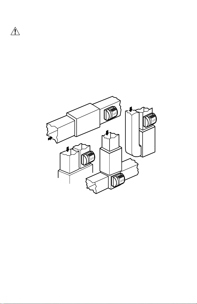
Installing the Pressure Switch
IMPORTANT
Do not install the switch in an area where temperature exceeds rating of
-40°F to 190°F (-40°C to 88°C).
1. Disconnect power from the humidifier before
installing.
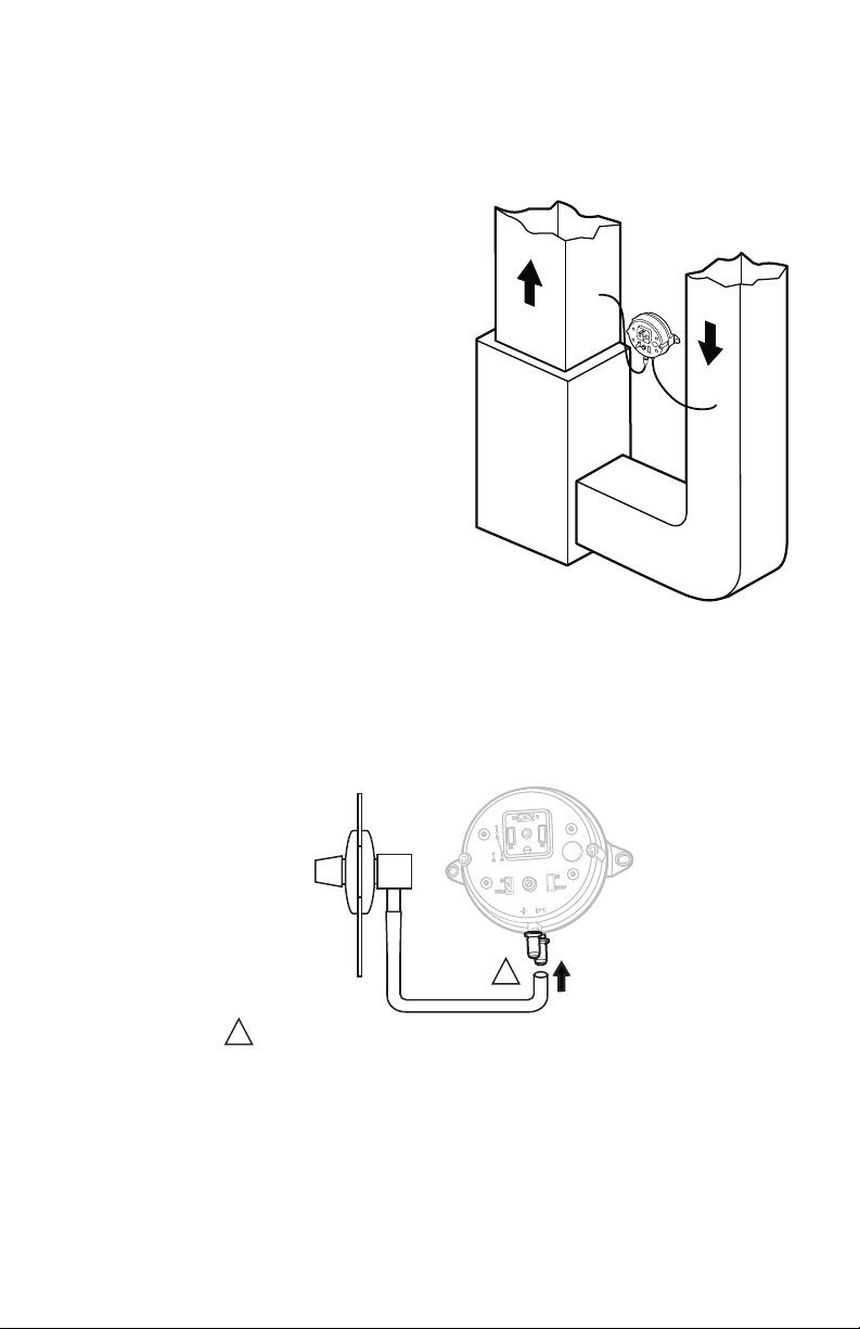
2. Mount the switch vertically with pressure
connectors facing down, using provided self-
tapping screws to secure the switch to the duct.
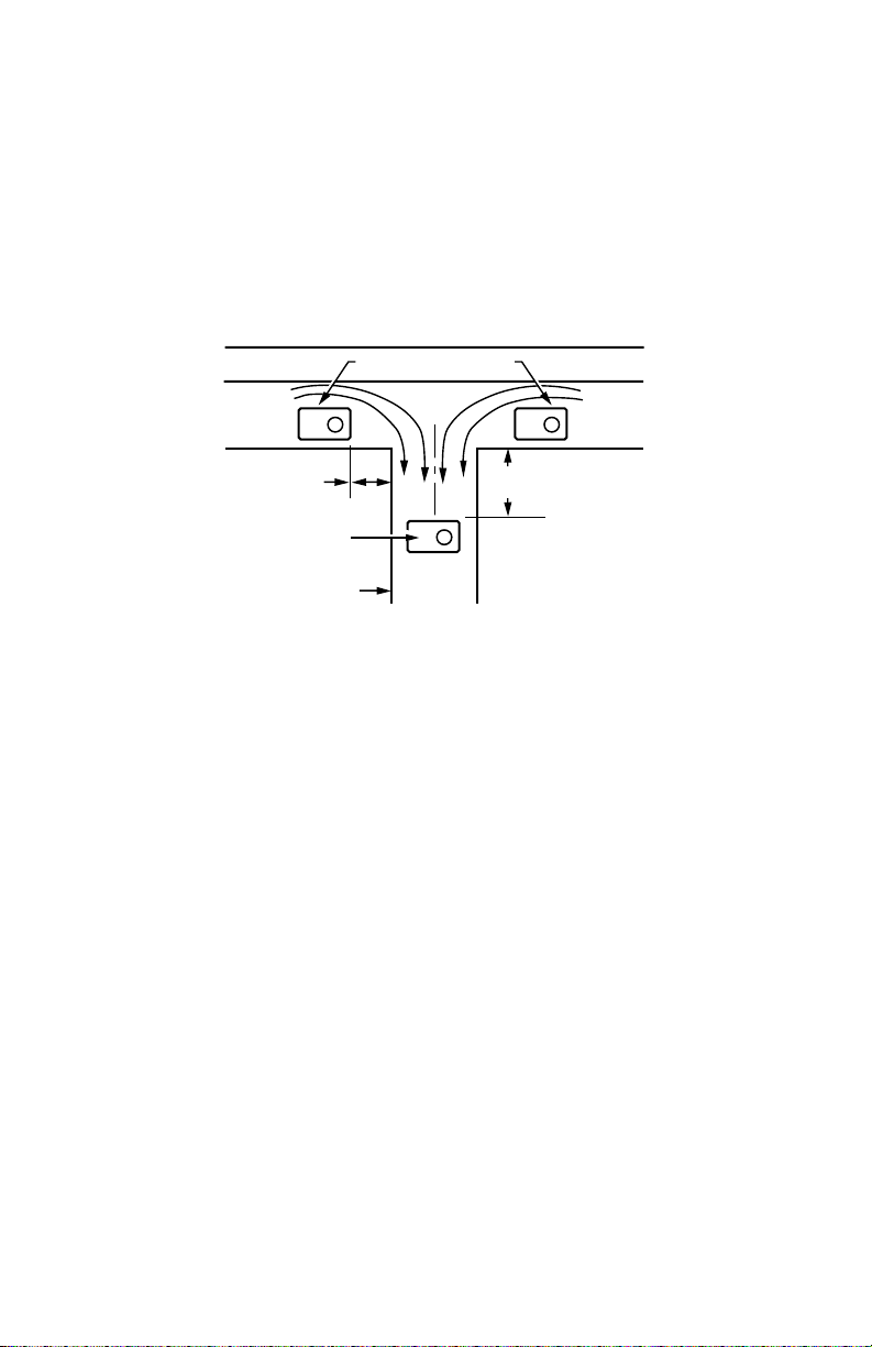
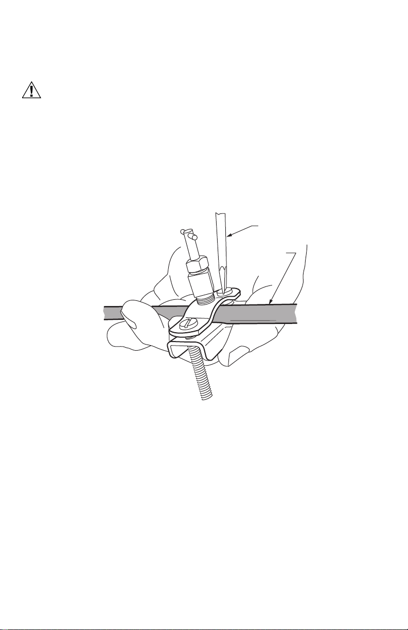
3. Cut 3/4-in. (19 mm) diameter holes in the
supply and return ducts within 10 feet of the
switch to ensure the provided tubing reaches the
pressure tap elbows. See Fig. 9.
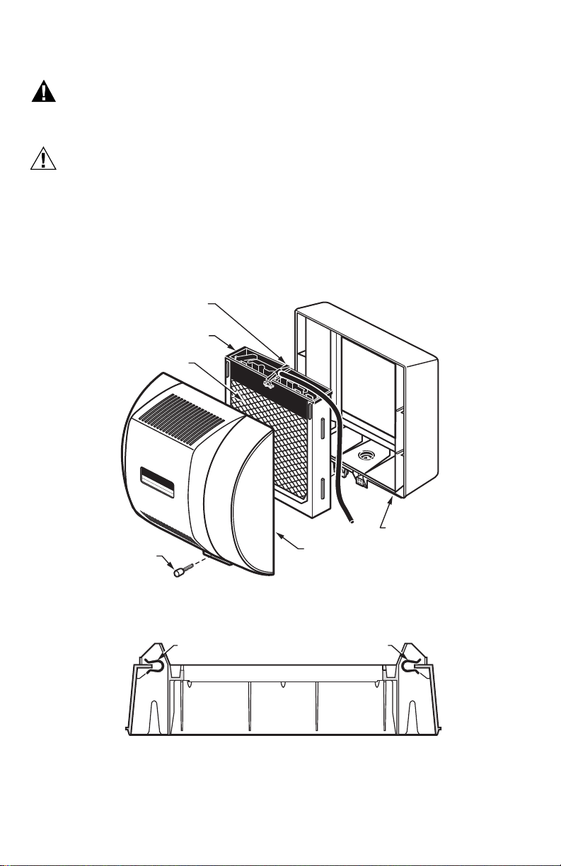
4. Insert the black rubber gaskets into the duct
holes.
5. Connect the tubing to the tubing fitting elbows
and insert the tubing fitting elbows into the
black rubber gaskets in each duct.
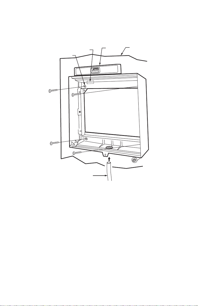
6. Connect the other end of the tubing to the
applicable pressure connection on the switch.
a. Connect supply duct tubing to the +
connection.
b. Connect return duct tubing to the –
connection
7. You may cut the tubing to fit the connection
length between the elbow fitting and switch. It is
also recommended to secure the hose to
existing structures to avoid accidental
disconnection.
Fig. 9. Mounting the pressure switch.
Fig. 10. Install tubing.
M27303
A
B
SUPPLY DUCT INSTALL - AIR LINE ONLY TO TAP A,
CONNECTED TO THE + PORT ON THE AIR FLOW SWITCH
RETURN DUCT INSTALL - AIR LINE ONLY TO TAP B,
CONNECTED TO THE – PORT ON THE AIR FLOW SWITCH
SUPPLY/RETURN DUCT INSTALL - AIR LINE CONNECTED
TO BOTH THE + AND – PORTS ON THE AIR FLOW SWITCH
M27304A
INSIDE
OF DUCT
CONNECT TUBING TO + CONNECTION IF PRESSURE TAP IS
MOUNTED TO SUPPLY DUCT. CONNECT TO – IF PRESSURE
TAP IS MOUNTED TO RETURN DUCT.
1
1

HE360 HUMIDIFIER AND INSTALLATION KIT
11 69-2631ES—07
Installing the Humidistat
Installing on Mounting Duct
1. Apply the template to the duct location chosen for the humidistat. Make sure the template is level before
drilling the holes.
2. Refer to the template (provided with the H8908 Humidistat Installation Instructions) to drill the control
assembly opening and mounting holes for the H8908.
3. Remove the H8908 case from the base.
4. Position the foam gasket on the H8908 base.
5. Position the base on the duct with the arrow up.
6. Secure the base to the duct using the four 1 in. (25 mm) mounting screws provided with humidistat.
NOTE: For wall mounting instructions, see the H8908 Installation Instructions.
Fig. 11. Humidistat base and rear view.
M20179
WIRE SLOT HUMIDISTAT WIRES
HUMIDISTAT BASE REAR OF HUMIDISTAT

HE360 HUMIDIFIER AND INSTALLATION KIT
69-2631ES—07 12
WIRING
CAUTION
Hazardous Voltage.
Can cause personal injury or equipment damage.
Disconnect power supply before installing or servicing equipment.
IMPORTANT
— Use THIS wiring diagram—NOT the one supplied with humidistat instructions.
— All wiring must comply with applicable local code, ordinances and regulations.
Wire the humidifier solenoid valve, pressure switch and humidistat. See Fig. 12.
NOTE: It is acceptable to switch the position of the red and white wires when wiring the equipment.
Fig. 12. Wiring the controls.
1. Run the two-strand thermostat wire from the humidifier to the humidistat, and from the humidistat to the
pressure switch.
2. Cut two (2) lengths of thermostat wire to reach between components, leaving adequate wire at both ends
for connections.
NOTE: Humidistat and pressure switch can be wired in any order.
3. At the humidifier, use one length of thermostat wire to connect a red wire to one of the yellow humidifier
wires and a white wire to the remaining yellow humidifier wire. (The red wires from the humidifier are not
used.)
4. At the pressure switch, use the remaining length of thermostat wire to connect a red wire to the C terminal
and a white wire to the NO terminal using spade connectors and pliers. (The NC terminal is not used.)
5. Connect the white wires from each length of thermostat wire to each of the black wires of the humidistat
using wire nuts.
6. Connect the remaining red wires together using a wire nut.
M34590A
HumidityControl
Régulateurd'humidité
-20¡F
-10¡F
0¡F
+10¡F
+20¡F
Over20¡F
15%
20%
25%
30%
35%
40%
HUMIDITY
SETTING
OUTDOOR
TEMPERATURE
-30¡C
-25¡C
-20¡C
-10¡C
-5¡C
Over0¡C
HUMIDISTAT AIR PRESSURE
SWITCH
YELLOW YELLOW
RED WHITE
BLACK BLACK
RED
WHITE WHITE
HUMIDIFIER
RED
WHITE RED

HE360 HUMIDIFIER AND INSTALLATION KIT
13 69-2631ES—07
TESTING HUMIDIFIER OPERATION
Checklist
Humidifier is level.
Control wiring was reviewed using circuit diagram.
Humidifier is plugged in.
Feed line has no kinks.
Drain line slopes continuously down and ends at floor drain.
Water hose inside humidifier is connected to PerfectFlow™ water distribution tray.
After installation use the following steps to check the humidifier operation:
1. Turn on the power and the water supply.
2. Turn the H8908 Humidistat to On and turn on the heat by setting the thermostat to 10ºF (6ºC) above room
temperature.
IMPORTANT
The furnace blower must be on to activate the humidifier.
3. Make sure that water is flowing out of the drain hose. If water does not flow, see Troubleshooting Your
Humidifier section.
4. Check for leaks.
5. Reset the thermostat and H8908 Humidistat to a comfortable setting for automatic operation.
OPERATION
How Your Humidifier Works
Your Resideo humidifier uses the principle that vapor (evaporated water) is created when warm air blows over a
water-soaked area. As the vapor circulates, the relative humidity rises.
Your humidity control monitors the relative humidity and activates the humidifier accordingly. The humidifier
has a water supply that dispenses water evenly over a humidifier pad. The warm dry air, from the furnace, passes
over the humidifier pad and picks up the moist air to circulate it throughout your home.
Humidified air feels warmer and more comfortable so you may be able to lower your thermostat heating
setpoint, which saves money on your heating fuel bills. The end result is that your humidifier gives you a
comfortable environment that is also energy efficient.
Controlling Your Humidity Settings
Your H8908 Humidistat controls your humidifier.
• Choose the humidity control setting using the combination of relative humidity/outdoor temperature setting
scale on your humidity control dial.
• Match the dial setting to the outdoor temperature to optimize the humidity level while reducing the moisture
condensation on your windows. See Table 2 to adjust the humidity control to the recommended setting.
NOTE: As the outside temperature drops, a lower humidity setting is recommended to accommodate dewpoint
effects. These settings should reduce the accumulation of moisture and ice on windows and other areas
of the home.
• Adjust the humidity control setting to adjust for indoor activities such as cooking, showering and clothes
drying, which can cause excessive levels of humidity that can accumulate moisture on your windows.
NOTE: If these activities persist for more than a few hours, set the humidity control to the lowest setting to turn
off the humidifier. If the condition does not improve, ventilate your home to remove the moisture.
Table 2. Setting Your Humidistat.
When Outside
Temperature is:
Use This Control
Setting:
-20°F (-29°C) 15
-10°F (-23°C) 20
0°F (-18°C) 25
+10°F (-12°C) 30
+20°F (-7°C) 35
Above 20°F (-7°C) 40

HE360 HUMIDIFIER AND INSTALLATION KIT
69-2631ES—07 14
MAINTAINING YOUR HUMIDIFIER
A regular maintenance program prolongs the life of your humidifier and makes your home more comfortable.
The frequency of cleaning depends on the condition of your water.
You can use either hard or soft water in your humidifier, but hard water mineral deposits are more difficult to
clean than soft water deposits.
Use the following procedure to clean your Resideo humidifier.
WARNING
Serious Personal Injury Hazard.
Can cause electrical shock and injury from moving parts.
Disconnect power and shut off water supply before removing cover.
IMPORTANT
Never oil any part of the humidifier.
Every 1 to 3 Months (Depending on Water Quality)
1. Disconnect the power and turn off the humidifier water supply.
2. Remove the humidifier cover by unplugging the connector and loosening the thumb screw. Grasp the
cover near the bottom and pull toward you. See Fig. 13.
3. Remove the humidifier pad assembly from the humidifier by grasping the top of the tray and pulling it
toward you.
4. Lift the tray off the pad.
5. Gently pinch the water nozzle catches inward until you can lift the water nozzle off the tray.
6. Carefully remove any mineral deposits from the tray and frame. Be sure the frame drain hole has nothing
blocking it.
Fig. 13. Cleaning your humidifier.
7. Disconnect the drain hose from the drain fitting on the bottom of the humidifier housing.
8. Clean the drain fitting, if necessary.
9. Bend the drain hose to loosen any mineral deposits.
10. Flush the drain hose with pressurized water (a running tap) to clean the hose.
11. Reattach the drain hose to the drain fitting.
12. Snap the water nozzle back on the tray.
13. Be sure the marked end of the pad is facing up. Place the tray on the new pad.
14. Place the humidifier pad assembly in the humidifier housing. Be sure the water feed tube is placed in the
guide slots.
15. Replace the humidifier cover.
16. Verify the humidifier operation by following the steps in the Checking Your Humidifier for Correct Opera-
tion section.
M12809A
COVER
ASSEMBLY
HUMIDIFIER
PAD ASSEMBLY
FEED TUBE NOZZLE
WATER
DISTRIBUTION TRAY
HUMIDIFIER
HOUSING
THUMB
SCREW

HE360 HUMIDIFIER AND INSTALLATION KIT
15 69-2631ES—07
CHECKING YOUR HUMIDIFIER FOR CORRECT OPERATION
After winter startup or servicing, use the following steps to check your humidifier operation:
1. Turn on the humidifier power and water supply.
2. Turn the humidistat to its highest setting and set the thermostat to 10°F (6°C) above the room tempera-
ture.
3. Observe that water is flowing out of the drain hose.
NOTE: The furnace blower must be running to activate the humidifier.
4. Reset the thermostat and humidistat to a comfortable setting for automatic operation.
TROUBLESHOOTING YOUR HUMIDIFIER
Table 3. Troubleshooting Humidifier.
Problem What to look for What to do
Water leakage Leaking joints. Shut off water.
Tighten connections.
Brass tubing inserts Verify that brass tubing inserts are used.
Saddle valve leaking. Verify rubber pad is installed on saddle valve.
No water to
drain. Electrical Verify control circuit wiring.
Check all connections.
Humidistat Turn humidistat up and down and listen for contact to click.
Humidifier power Verify that outlet has power.
Solenoid After verifying other wiring components, turn on furnace fan,
turn humidistat up and down, and listen for solenoid to click.
Plumbing Verify plumbing connections.
Check for kinks.
Saddle valve Verify that needle pierces water line and then backs out
needle to open valve.
Humidifier Remove cover and verify that water flows into distribution
tray.
Drain tubing Verify no obstructions.
Low humidity Furnace blower not
operating. •Reset circuit breaker or check for blown fuse.
•Check that the furnace power is on.
•Check all external wiring connections.
•Check the humidity control setting.
•Call a professional heating contractor.
Rapid air changes. Drafts
(cold air is dry and is an
added load to the
humidifier).
•Keep doors and windows closed.
•Close fireplace damper when not in use.
•Keep exhaust fan running time to a minimum.
•Seal around doors and windows.
High humidity Condensation on walls. •Turn off humidity control and water until condensation is
completely evaporated.
Heavy condensation on
windows. •Turn humidity control down low enough to eliminate
condensation caused by moisture from bathing,
mopping, cooking, etc. If moisture persists, more
ventilation is needed.

HE360 HUMIDIFIER AND INSTALLATION KIT
This product is manufactured by Resideo Technologies, Inc., Golden Valley, MN, 1-800-468-1502
©2019 Resideo Technologies, Inc. The Honeywell Home trademark is used under license from Honeywell International Inc. All rights reserved.
www.resideo.com
Resideo Inc., 1985 Douglas Drive North,
Golden Valley, MN 55422
69-2631ES—07 M.S. Rev. 09-19 | Printed in United States
LIMITED ONE-YEAR WARRANTY
Resideo warrants this product, excluding battery, to be free from defects in workmanship or materials, under
normal use and service, for a period of one (1) year from the date of first purchase by the original purchaser. If at
any time during the warranty period the product is determined to be defective due to workmanship or materials,
Resideo shall repair or replace it (at Resideo’s option).
If the product is defective,
(i) return it, with a bill of sale or other dated proof of purchase, to the place from which you purchased it; or
(ii) call Resideo Customer Care at 1-800-468-1502. Customer Care will make the determination whether the
product should be returned to the following address: Resideo Return Goods, 1985 Douglas Dr. N., Golden Valley,
MN 55422, or whether a replacement product can be sent to you.
This warranty does not cover removal or reinstallation costs. This warranty shall not apply if it is shown by
Resideo that the defect was caused by damage which occurred while the product was in the possession of a
consumer.
Resideo’s sole responsibility shall be to repair or replace the product within the terms stated above. RESIDEO
SHALL NOT BE LIABLE FOR ANY LOSS OR DAMAGE OF ANY KIND, INCLUDING ANY INCIDENTAL OR
CONSEQUENTIAL DAMAGES RESULTING, DIRECTLY OR INDIRECTLY, FROM ANY BREACH OF ANY
WARRANTY, EXPRESS OR IMPLIED, OR ANY OTHER FAILURE OF THIS PRODUCT.
Some states do not allow the exclusion or limitation of incidental or consequential damages, so this limitation
may not apply to you.
THIS WARRANTY IS THE ONLY EXPRESS WARRANTY RESIDEO MAKES ON THIS PRODUCT. THE DURATION OF
ANY IMPLIED WARRANTIES, INCLUDING THE WARRANTIES OF MERCHANTABILITY AND FITNESS FOR A
PARTICULAR PURPOSE, IS HEREBY LIMITED TO THE one YEAR DURATION OF THIS WARRANTY. Some states
do not allow limitations on how long an implied warranty lasts, so the above limitation may not apply to you.
This warranty gives you specific legal rights, and you may have other rights which vary from state to state. If you
have any questions concerning this warranty, please write Resideo Customer Care, 1985 Douglas Dr, Golden
Valley, MN 55422 or call 1-800-468-1502.

MANUAL DE INSTRUCCIONES
Humidificador HE360 y
kit de instalación
HE360A1075
Leer antes de instalar
Entrada: 120 V CA, 60 Hz, 0.7A

HUMIDIFICADOR HE360 Y KIT DE INSTALACIÓN
69-2631ES—07 2
BIENVENIDO
Le damos la bienvenida al mundo confortable del aire humidificado. Cuando utilice su humidificador Resideo,
observará que su piel no estará tan seca, y que la garganta rasposa y los conductos nasales irritados que
agravan las alergias y el asma mejorarán continuamente.
También ha dado el primer paso para disminuir la electricidad estática que crea cuando camina en la alfombra
y, luego, toca el televisor, la computadora, el pomo de metal de la puerta o su mascota. Sus muebles y la madera
también se benefician de la diferencia que el aire humidificado crea.
¡Felicitaciones! Ha hecho una estupenda inversión para mejorar el confort de su hogar.
APLICACIÓN
Este kit contiene su nuevo humidificador Resideo HE360, el humidistato H8908 y todos los accesorios
necesarios para la instalación.
INSTALACIÓN
Preparación para la instalación
Cerciórese de identificar todos los accesorios necesarios que se incluyen (Tabla 1) y de tener disponibles los
implementos adecuados antes de comenzar la instalación.
Herramientas necesarias
Las herramientas necesarias para la instalación son las siguientes:
• Tijera de hojalata.
•Destornillador.
• Llave ajustable o de extremo abierto.
• Taladro o punzón.
•Nivelador.
•Alicate.
•Llaveparatuercas.
• Pelacables.
• Broca para taladro de ¾ de pulgada (19 mm).

HUMIDIFICADOR HE360 Y KIT DE INSTALACIÓN
3 69-2631ES—07
Accesorios incluidos
Tabla 1. Accesorios incluidos.
Cantidad Accesorio
6.2 m (20 pies) Cable calibre 18 de dos conductores para termostato
6.2 m (20 pies) Tubería de alimentación de agua con diámetro externo de
6mm(1/4in)
3 m (10 pies) Tubería de drenaje con diámetro interno de 13 mm (1/2 in)
2 bolsas
Elementos de montaje y conexión:
1 Interruptor de presión
1 Humidistato H8908
1 bolsa Ensamble de válvula de montura:
• Válvula de montura y abrazadera
superior (1)
• Abrazadera inferior roscada (1)
•Pernos(2)
• Junta de goma (1)
•Armella(1)
• Cojinete plástico (1)
MS34594
TORNILLOS Nº 8 PARA
LÁMINA DE METAL (18)
TORNILLOS AUTOPERFORANTES (2)
EMPALMES PARA CABLES (5)
ABRAZADERA PARA EL
TUBO DE DRENAJE (1)
ABRAZADERAS DE MONTAJE PARA
EL TUBO DE ALIMENTACIÓN (6)
INSERTOS DE LATÓN (2)
AROS DE COMPRESIÓN
PLÁSTICOS (2)
CONECTORES DE HORQUILLA (2)
CODO DE TUBERÍA (2)
JUNTA DE GOMA NEGRA (2)
BOLSA Nº 1 BOLSA Nº 2
M34599
HumidityControl
Régulateurd'humidité
-20¡F
-10¡F
0¡F
+10¡F
+20¡F
Over20¡F
15%
20%
25%
30%
35%
40%
HUMIDITY
SETTING
OUTDOOR
TEMPERATURE
-30¡C
-25¡C
-20¡C
-10¡C
-5¡C
Over0¡C
M38020
MS31000A
ENSAMBLE
DE VÁLVULA
DE MONTURA
VÁLVULA DE
MONTURA
PERNOS
ABRAZADERA
INFERIOR
JUNTA
DE GOMA
ABRAZADERA
SUPERIOR

HUMIDIFICADOR HE360 Y KIT DE INSTALACIÓN
69-2631ES—07 4
Cómo determinar la mejor ubicación para el humidificador
PRECAUCIÓN
Temperatura y peligro de presión estática.
Puede dañar la propiedad o el equipo.
Ubique el humidificador donde la temperatura ambiente esté entre 0 °C (32 °F) y 71 °C (160 °F).
No instale el humidificador donde pudiesen ocurrir temperaturas de congelamiento.
Cerciórese de que la presión estática en el plenum no sea mayor de 0.4 en la columna de agua y que la
presión de agua no sea mayor de 124 psi.
• Elija un lugar para el humidificador en el plenum de alimentación (corriente de aire cálido). Consulte la Fig. 1.
• Elija un lugar que no pueda dañar el serpentín A del aire acondicionado durante la instalación.
• No ubique el humidificador en el interior del sistema de calefacción.
• Permita el espacio libre adecuado al frente y sobre el humidificador para que pueda retirar fácilmente la
cubierta para efectuar el mantenimiento de rutina.
— Monte el humidificador, al menos, 78 mm (3 in) por encima del sistema de calefacción para permitir
suficiente espacio para la válvula del solenoide y la tubería de drenaje.
— Monte el humidificador en un espacio acondicionado para evitar el congelamiento.
Fig. 1. Ubicaciones de instalación típicas para el humidificador.
MS12808
HORIZONTAL
PLATAFORMA BAJA
RETORNO
RETORNO
RETORNO
RETORNO
FLUJO
DESCENDENTE
PLATAFORMA
ALTA
Other manuals for HE360
2
This manual suits for next models
1
Table of contents
Languages:
Other Honeywell Home Humidifier manuals

Honeywell Home
Honeywell Home HE105 User manual

Honeywell Home
Honeywell Home HE105 User manual

Honeywell Home
Honeywell Home HE400 User manual

Honeywell Home
Honeywell Home HE365 User manual

Honeywell Home
Honeywell Home HE365 User manual

Honeywell Home
Honeywell Home HE240 User manual

Honeywell Home
Honeywell Home HC18A User manual

Honeywell Home
Honeywell Home HE360 User manual

Honeywell Home
Honeywell Home HE100A1000 User manual

Honeywell Home
Honeywell Home HE360 User manual