Template (entire sheet) Top of Humidifier
Template (entire sheet)
Template (entire sheet)
Template (entire sheet)
This product is manufactured by Resideo Technologies, Inc., Golden Valley, MN, 1-800-468-1502
©2019 Resideo Technologies, Inc. The Honeywell Home trademark is used under license from Honeywell International Inc. All rights reserved.
www.resideo.com
Resideo Inc., 1985 Douglas Drive North,
Golden Valley, MN 55422
33-00511—01 M.S. 11-19 | Printed in United States
WIRING
Voltage Hazard.
Moving parts can cause electrical shock and injury.
•Disconnect power supply before installation or
servicing.
•This device contains a moving fan blade; do not operate
the humidifier without the cover securely attached.
All wiring must comply with applicable local codes,
ordinances and regulations.
For H808 Humidistat, H8908 or H908
Convertible Humidity Control Wiring
Connections:
IMPORTANT
• Select models of fan centers include humidifer taps so the
current sensing relay or sail switch is not needed.
• If not using a current sensing relay or sail switch, the
120V humidifier plug must be energized during blower
motor cycles for proper operation.
12. Wire the current sensing relay or sail switch.
13. Connect only the two yellow wires to the humidistat (red
wire connections are not used for mechanical humidistats).
See the typical wiring diagrams in Fig. 5 through 7.
For additional mounting and wiring information, refer to the
humidistat installation instructions.
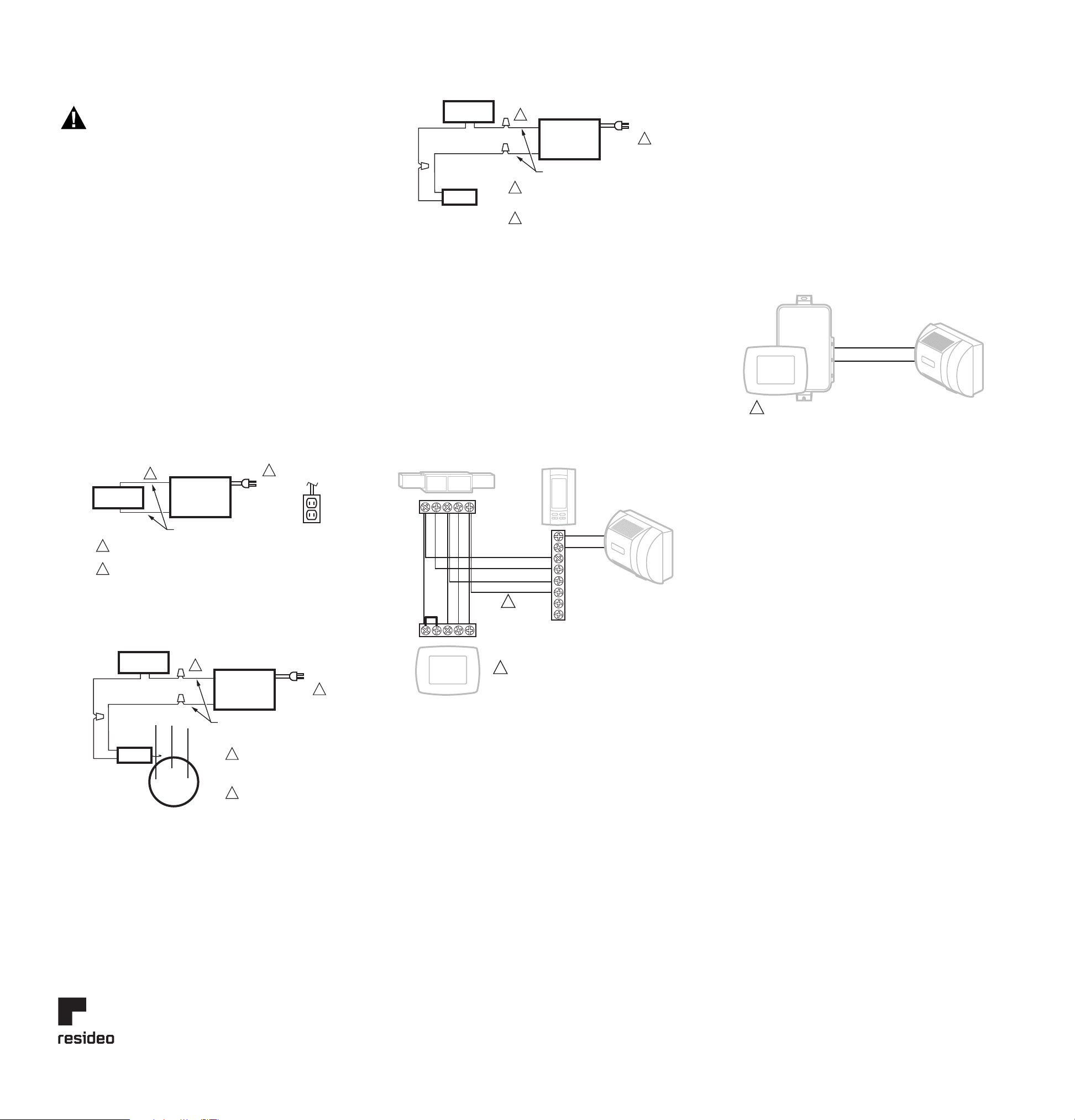
Fig. 5. Typical wiring diagram for humidifier using fan control
to cycle blower motor fan and humidifier simultaneously.
Fig. 6. Typical wiring diagram of current sensing relay with
humidifier.
Fig. 7. Typical wiring diagram of sail switch with humidifier.
For H1008 Automatic Humidity Control wiring
connections:
IMPORTANT
• Current sensing relay or sail switch is not needed with the
Automatic Humidity Control.
• Use 18-22 gauge insulated wire for proper wiring. We
recommend stranded - tinned wire.
14. Connect 24 Vac power to the 24 Vac HOT and COM
terminals on the H1008A.
15. Connect the humidifier to the two HUM terminals on the
H1008A as shown in Fig. 8.
For additional mounting and wiring information, refer to the
Humidity Control installation instructions.
Fig. 8. Typical wiring diagram for humidifier using TrueIAQ.
CHECKOUT
1. Set the thermostat setpoint 10°F (6°C) above the room
temperature.
2. Set the humidity control to a high humidity setting, or place
the setting in the test position.
3. Observe the water running out of the drain line to be sure
the humidifier is working correctly.
4. Check for leaks.
5. Reset the thermostat to a comfortable setting or the
Automatic Humidity Control to the desired frost factor
setting.
NOTE: The furnace blower must be on for the humidifier to
operate.
Fig. 9. Typical wiring diagram for humidifier
using VisionPRO IAQ
HUMIDIFIER
MECHANICAL
HUMIDISTAT
120 VAC
TO BLOWER
MOTOR
IGNITION BOX
M12686B
YELLOW WIRES
1
1
2
2
POWER SUPPLY. PROVIDE DISCONNECT MEANS AND
OVERLOAD PROTECTION AS REQUIRED.
24V WIRING.
CURRENT
SENSING
RELAY
HUMIDIFIER
120 VAC
BLOWER
MOTOR
C
LO
HI
M12684B
YELLOW WIRES
1
1
2
2
POWER SUPPLY.
PROVIDE DISCONNECT
MEANS AND OVERLOAD
PROTECTION AS REQUIRED.
24V WIRING.
MECHANICAL
HUMIDISTAT
SAIL
SWITCH
HUMIDIFIER
120 VAC
M12685B
YELLOW WIRES
1
1
2
2
POWER SUPPLY. PROVIDE DISCONNECT
MEANS AND OVERLOAD PROTECTION
AS REQUIRED.
24V WIRING.
MECHANICAL
HUMIDISTAT
HVAC TRUEIAQ
THERMOSTAT
HUM
HUM
R
C
W
G
GYWRRC
GYWRC
YELLOW
IF A THERMOSTAT OTHER THAN TH5110, TH5220,
TH5320, TH6110, TH6220, TH6320, TH8110,
TH8320 OR TH8321 IS USED, A RELAY MAY BE
REQUIRED TO ISOLATE THE G WIRE.
1
1
M31027A
YELLOW
HUM
SET VISIONPRO IAQ ISU #372 AND #374 TO CONTROL FOR FROST
AND HVAC FAN OPERATION.
M31028A
1
Equipment Interface Module


