ADEMCO 4208U Universal V-Plex
®
Eight Zone Expander
INSTALLATION AND SETUP GUIDE
FEATURES
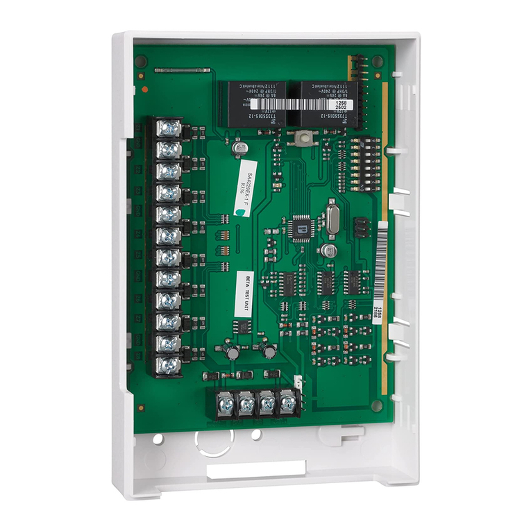
The ADEMCO 4208U is a V-Plex
®
eight-zone expande fo use
with ADEMCO cont ols that suppo t V-Plex
(polling loop)
devices. Cha acte istics of this device include:
•Can be optionally powe ed f om the cont ol panel aux.
powe supply to educe the amount of cu ent d aw f om
the polling loop. NOTE: The 4208U cannot be used with an
exte nal powe supply fo comme cial fi e applications.
•Uniquely identifies 8 EOLR supe vised zones (all zones use
10k esisto s, supplied).
•DIP Switches can be used to set zone numbe s o se ial
numbe s.
•When used in the se ial numbe mode, each se ial numbe
in the selected g oup can be assigned to any zone numbe .
•Loops A & B can be p og ammed fo fast (10msec)
esponse.
•Tampe p otected.
MOUNTING
1. Power should be disconnected before proceeding.
2.
Be sure to mount the 4208U before making any wiring
connections.
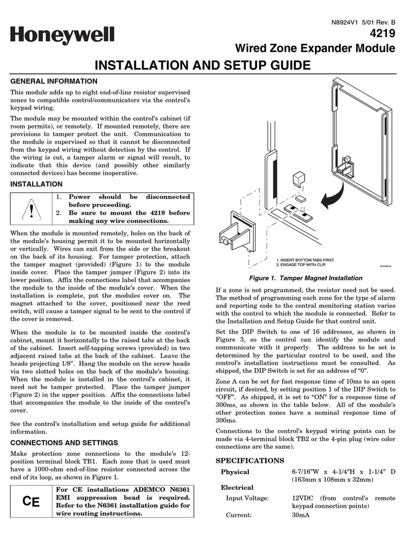
When mounted emotely, tampe p otection is equi ed. Holes
on the back of the module’s housing pe mit it to be mounted
ho izontally o ve tically. Wi es can exit f om the side o the
b eakout on the back of the housing. To enable tampe
p otection, set DIP Switch 8 to OFF and attach the tampe
magnet (p ovided) (Figu e 1) to the module inside cove . Be
su e to enable the expansion zone tampe option at the cont ol
(p og am field ✼24 = 0). If the module’s cove is emoved, the
magnet attached to the cove (positioned nea the eed switch)
will cause a tampe signal to be sent to the cont ol fo eve y
active zone on the 4208U module. When the installation is
complete, install the cove and affix the Se ial Numbe and
Zone Assignment Tables to the inside cove of the cont ol.
When mounted inside the cabinet with the cont ol, the 4208U
should be mounted ho izontally and does not need tampe
p otection, p ovided the cabinet is supe vised. Inse t two
sc ews into the aised metal tabs leaving the heads app. 1/8”
exposed, and then hang the 4208U using the two slots on the
back.
WIRING
CE
For CE installations ADEMCO N6361 EMI suppression
bead is required. Refer to the N6361 Installation
Instructions for wire routing instructions.
Polling loop and p otection loop wi es can be b ought in eithe
th ough the back o f ont of the unit by emoving the
knockouts.
Use 22 gauge twisted pai wi e fo polling loop connections. All
p otection loops use 10k EOL esisto s (included). A maximum
esistance of 300 ohms is allowed on p otection loops (excluding
EOLR). See Figu e 2 fo all connections.
Keep in mind that connections to the polling loop a e always
equi ed, while powe supply connections a e optional.
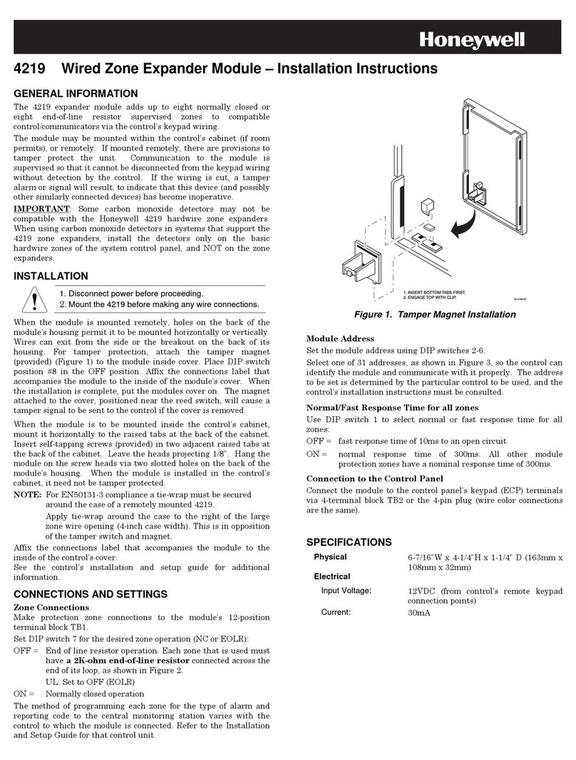
1. INSERT BOTTOM TABS FIRST.
2. ENGAGE TOP WITH CLIP.
4219-002-V0
Figure 1. Tamper Magnet Installation
DIP SWITCH SETTINGS
Serial Number Mode:
In the se ial numbe mode, the DIP Switches on the 4208U a e
used to assign the unit to a g oup of 8 se ial numbe s. You can
assign any se ial numbe to any zone numbe (except ha dwi e
zone numbe s of the cont ol) and you do not lose zone numbe s if
you don’t use all eight loops on the 4208U. Follow steps below
using Table 2 fo DIP Switch settings.
Zone Assignment Mode:
In the zone assignment mode, the DIP Switches on the 4208U a e
used to assign the unit to a g oup of 8 consecutive zones. These
zone numbe s, once designated fo the 4208U, cannot be used fo
anything else, even if you don’t use all 8. Follow the steps below
using Table 1 fo DIP Switch settings.
Note: Zone Assignment Mode should only be used on panels that
DO NOT suppo t Se ial Mode.
UL
1. For all fire (NFPA) and UL Commercial Burglary
installations, the 4208U must be tamper protected or
mounted in a tamper-protected cabinet.
2. Refer to the control panel installation instructions for
specific programming/installation requirements.
3. All circuits are supervised and power-limited.
4. Use only 14-22 AWG wire.
5. Close contact type initiating devices.
6. All zones are Class B, Style B.
7. Voltage rating all zones: 11VDC max., 1.5mA max.

