TRUEZONE ARD, EARD, AND ZD SERIES DAMPERS
333-00040—01
Installing the Round (ARD and
EARD) Dampers
1. Insert the crimped end of the ARD or EARD into the
uncrimped end of the rigid round duct and secure with
sheet metal screws (not provided). When using flexible
duct, slip the duct over the end of the ARD or EARD and
secure it with duct straps (not provided).
2. When installing the damper in a horizontal application,
make sure the motor actuator is located on the side or
top of the damper. Do not locate the motor on the bot-
tom of the damper. The damper can be mounted in a
vertical duct.
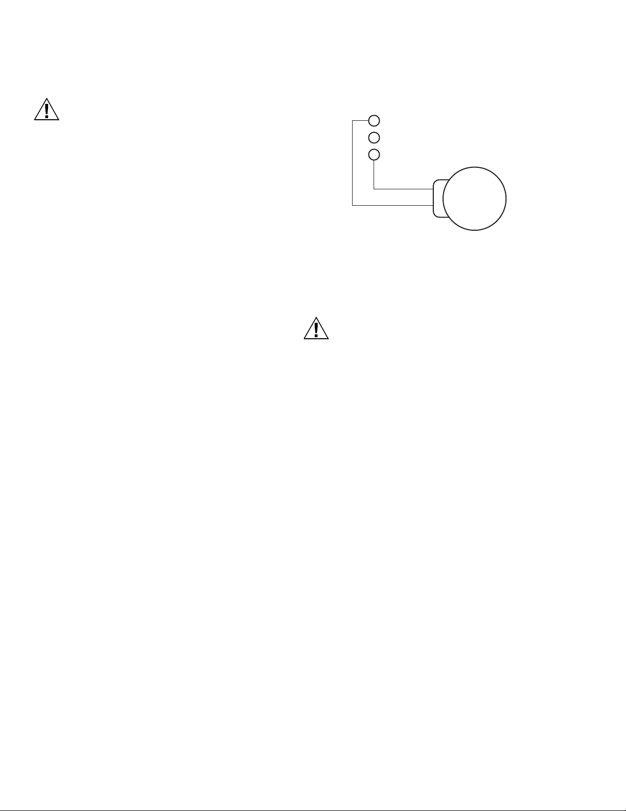
3. Adjust Range stop position to desired closed positions.
ARD and ZD Dampers are completely closed in position
0. EARD Dampers are completely open in position 0.
Fig. 2. TrueZONE Actuator range stop positions.
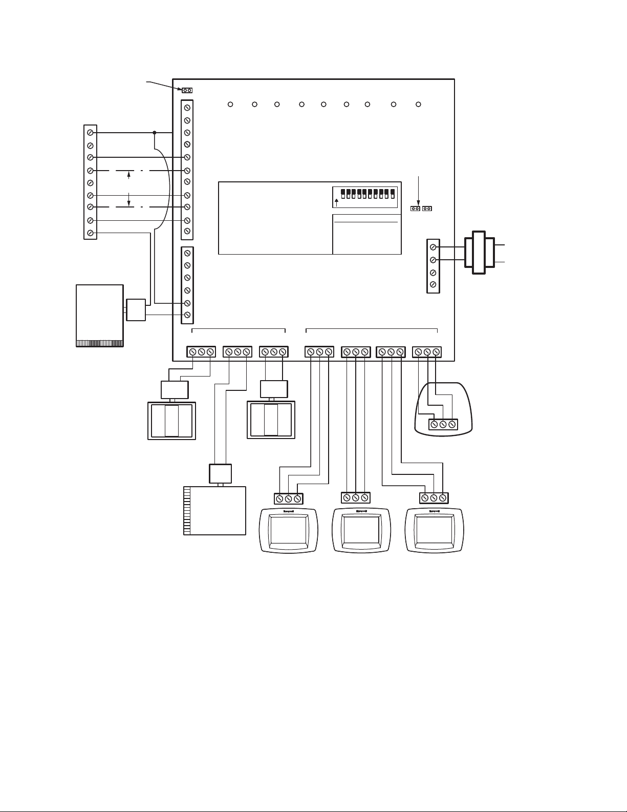
Wiring Multiple Dampers
When the same zone controls two or more dampers, wire the
dampers in parallel to terminals M1 and M6 on the zone
control panel.
INSTALLATION OF ZD DAMPER
When Installing this Product…
1. Read these instructions carefully. Failure to follow these
instructions can damage the product or cause a hazard-
ous condition.
2. Check the ratings given in the instructions and on the
product to make sure the product is suitable for your
application.
3. Installer must be a trained, experienced service techni-
cian.
4. All wiring must comply with local electrical codes, ordi-
nances, and regulations.
5. After completing installation, use these instructions to
check out the product operation.
Planning the Installation
Selecting a Location
Select a location for the zone dampers that is at least three
feet from the HVAC unit plenum in the air duct takeoff to the
respective zone and is easily accessible for checkout and
maintenance.
The ZD comes complete and ready for installation. The motor
and linkage are factory-assembled to the damper. The
damper is assembled for installation and wiring to the control
panel.
Selecting Damper Size
To ensure correct operation, be sure to select the correct zone
damper size for the air duct:
IMPORTANT
Be aware that damper sizes are built 5/32 in. smaller
than the listed dimensional sizes.
• If the damper is forced into an undersized air duct, the
excess pressure can jam the damper blades and cause
improper operation.
• When a small percentage of continuous flow is desired in a
zone, even when the damper blades are closed, adjust
motor closed position to be slightly open to maintain
desired air flow.
Selecting Location with Humidifier
Installed
IMPORTANT
Excessive lime or mineral deposits can accumulate
on damper blades and cause improper operation
when spray or atomizing type humidifiers are
installed in the furnace plenum or air supply duct with
the zone dampers.
• Spray or atomizer type humidifiers that are installed in the
furnace plenum or air supply duct are not recommended.
• Evaporative type humidifiers are recommended.
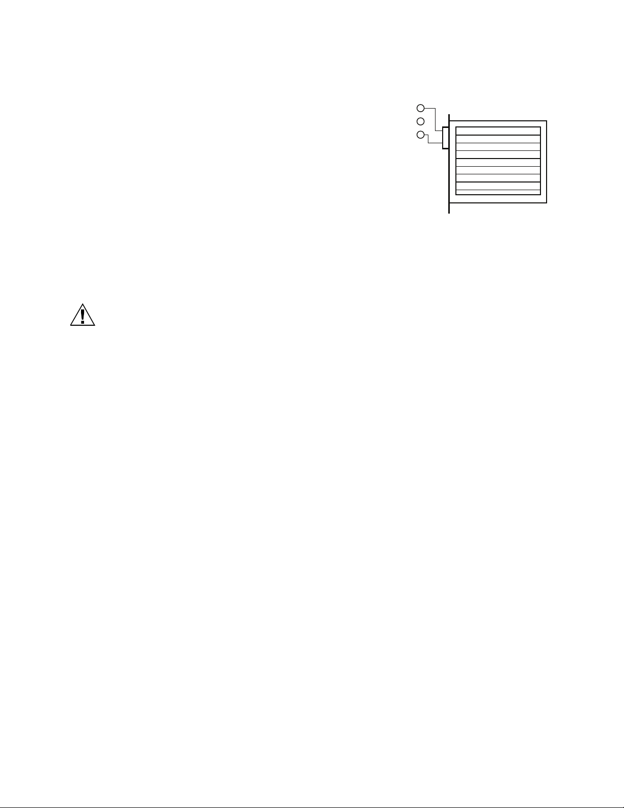
Installing the Damper
IMPORTANT
— Install dampers into a squared air duct.
— Do not weld dampers to the air ducts.
— Do not force dampers into undersized air ducts.
Excess pressure can damage damper blades.
— Be sure high limit setting is less than 200° F (93°C).
— Higher settings can damage the electric actuator.
1. Be sure the ZD is correctly sized to the air duct (see
Selecting Damper Size section).
2. Select a ZD location that is three feet from the furnace
plenum.
3. Cut a 4-in. (102 mm) opening in the accessible side of
the air duct at the location selected; ensure the opening
of the air duct is cut fully from seam to seam.
4. Secure the ZD mounting plate to the air duct with the
self-tapping sheet metal screws provided.
M35187
RANGE STOP
LOCATIONS