manuals.online logo
Brands
  1. Home
  2. •
  3. Brands
  4. •
  5. Honeywell
  6. •
  7. Monitor
  8. •
  9. Honeywell ZA-56025-000 User manual

Honeywell ZA-56025-000 User manual

Other Honeywell Monitor manuals

Honeywell IAQPoint2 User manual

Honeywell

Honeywell IAQPoint2 User manual

Honeywell BW RigRat User manual

Honeywell

Honeywell BW RigRat User manual

Honeywell IAQPoint2 User manual

Honeywell

Honeywell IAQPoint2 User manual

Honeywell Fire-lite Alarms ANN-80-W Technical manual

Honeywell

Honeywell Fire-lite Alarms ANN-80-W Technical manual

Honeywell HMC14HR User manual

Honeywell

Honeywell HMC14HR User manual

Honeywell 7800 SERIES User manual

Honeywell

Honeywell 7800 SERIES User manual

Honeywell 315-080 Technical manual

Honeywell

Honeywell 315-080 Technical manual

Honeywell HMLCD19 User manual

Honeywell

Honeywell HMLCD19 User manual

Honeywell C7355A User manual

Honeywell

Honeywell C7355A User manual

Honeywell HMLCD17L User manual

Honeywell

Honeywell HMLCD17L User manual

Honeywell IAQPoint User manual

Honeywell

Honeywell IAQPoint User manual

Honeywell HMLCD17E2 User manual

Honeywell

Honeywell HMLCD17E2 User manual

Honeywell HMC21 User manual

Honeywell

Honeywell HMC21 User manual

Honeywell MeshGuard FTD-2000 User manual

Honeywell

Honeywell MeshGuard FTD-2000 User manual

Honeywell NOTIFIER NCD User manual

Honeywell

Honeywell NOTIFIER NCD User manual

Honeywell CM4 Release Note

Honeywell

Honeywell CM4 Release Note

Honeywell NOTIFIER FMM-1 User manual

Honeywell

Honeywell NOTIFIER FMM-1 User manual

Honeywell 7561-PSDS User manual

Honeywell

Honeywell 7561-PSDS User manual

Honeywell SV2 Series User manual

Honeywell

Honeywell SV2 Series User manual

Honeywell HMLCD19e2 User manual

Honeywell

Honeywell HMLCD19e2 User manual

Honeywell SC500 User manual

Honeywell

Honeywell SC500 User manual

Honeywell GENESIS DM User manual

Honeywell

Honeywell GENESIS DM User manual

Honeywell P531 User manual

Honeywell

Honeywell P531 User manual

Honeywell S7760A User manual

Honeywell

Honeywell S7760A User manual

Popular Monitor manuals by other brands

Samsung ME32C user manual

Samsung

Samsung ME32C user manual

ViewSonic VA926-LED user guide

ViewSonic

ViewSonic VA926-LED user guide

Furuno Mu 120c Operator's manual

Furuno

Furuno Mu 120c Operator's manual

Asus VB171D - 17" LCD Monitor Service manual

Asus

Asus VB171D - 17" LCD Monitor Service manual

AOC 9GLR Technical specifications

AOC

AOC 9GLR Technical specifications

DMG RAFFAELLO manual

DMG

DMG RAFFAELLO manual

AOC LM720 - 17" Technical specifications

AOC

AOC LM720 - 17" Technical specifications

Sony Trinitron GDM-F500 Service manual

Sony

Sony Trinitron GDM-F500 Service manual

Memorex MT1701 user guide

Memorex

Memorex MT1701 user guide

ViewSonic VE510s-4 Service manual

ViewSonic

ViewSonic VE510s-4 Service manual

Farenheit T-1503CM instruction manual

Farenheit

Farenheit T-1503CM instruction manual

Ditel DINOS DN129/AT Quick installation guide

Ditel

Ditel DINOS DN129/AT Quick installation guide

Sony SDM-S51 Specifications

Sony

Sony SDM-S51 Specifications

Kenwood DMX1025BT quick start guide

Kenwood

Kenwood DMX1025BT quick start guide

Dell S2409WFP user guide

Dell

Dell S2409WFP user guide

EverFocus EN-7517E instruction manual

EverFocus

EverFocus EN-7517E instruction manual

Dell P3222QE user guide

Dell

Dell P3222QE user guide

Panasonic TH152UX1 - 152" PLASMA TV Service manual

Panasonic

Panasonic TH152UX1 - 152" PLASMA TV Service manual

manuals.online logo
manuals.online logoBrands
  • About & Mission
  • Contact us
  • Privacy Policy
  • Terms and Conditions

Copyright 2025 Manuals.Online. All Rights Reserved.

Honeywell Cooling & Refrigeration, Newhouse Industrial Estate, Motherwell ML1 5SB Scotland, U.K.
Tel: +44 (0)1698 481698 Fax: +44 (0)1698 481699 www.honeywell.com/cooling
DIN Box Display (with Keyswitch)
Installation Guide
Product Part No:
ZA-56025-000
DIN Box Display (with Keyswitch) 191305
Issue b : 5/8/98
Features:
?? Quick and simple LED visual access to individual case or
coldroom operating temperatures.
?? Displays any messages, and toggles between message
and current value.
?? Displays status for alarm, network, defrost and setting
mode.
?? Control parameters easily set or edited using only four
buttons.
?? High or Low temperature range easily selected using
Keyswitch
Warning !
Before you work on this equipment, isolate the
electrical supply and also the live feed to any
incoming signals. Remember that live signals may
be derived from more than one source.
15
Blue
Black
White
Green
Red
Yellow
Fig. 1A
CN9 Black (common)
Blue (S/C)
Green (5k6)
Tuscan (Keyswitch) Connection
(using cable - 790752 or 791305)
x1
x2
x3
x4
Blue
YellowGreen
Red White
blue
green
yellow
white
red
CN8
Tuscan (Display) Connection
(using cable - 790385)
Fig. 1B
Associated Documents:
?? Health and Safety: ZG 1056
1. Tab
2. Keyswitch
3. Display unit
4. Keyswitch board
5. Keyswitch connector
6. Top notch
7. Door flap tab location
8. Display housing
9. Grommets x 2
10. Push-out panels
11. Housing cut-out
12. Display Board
13. Display lead connector
14. Bottom notch
15. Door flap
Fig. 1
ZA56025-000 Issue b : 5/8/98
2
Installation Guide Continued
Remove Door Flap (Fig. 2)
Hold DIN Box Display in one hand, open door flap
(15) then apply pressure to flap (in direction of
arrow). The door flap should flex until each tab (1)
disengages in turn with each of the door flap tab
locations (7) in display housing (8). Remove door
flap.
Note: Care must be taken not to
apply excess pressure to
flap, otherwise damage may occur.
Remove Display Unit (Fig. 1)
Carefully insert screwdriver, by no more than 5mm. depth, between bottom notch (14) in display unit (3) and housing
cut-out (11). Lever downwards to separate display unit from housing. Remove display unit with fingers
Connect Wiring (Fig.1)
The Din Box Display housing (8) has 4 push-out panels (10), two in the top face and two in the rear face of housing.
Two of these panels must be knocked out, to allow cable connectors to be fed through the housing and into the display
board (12).
There are two rubber grommets located inside the rear face of display housing.
Remove both grommets then, using a scalpel or sharp knife, cut a slit of approximately 2cm. in each grommet.
Fit grommets (9) over display cable and keyswitch cable connectors respectively, then slide grommets along cables,
approximately 10cm. from the connectors.
Pass display lead connector through left hand aperture in housing, looking at display from front, then plug into display
connector (13) in display board (12). See Fig 1B for Tuscan controller board CN8 connection.
Pass Keyswitch connector through right hand aperture in housing, looking at display from front, then plug into 6 pin
Keyswitch connector (5) in keyswitch board (4). See Fig 1A for Tuscan controller board CN9 connection.
Fit grommets into their respective apertures, ensuring that they are correctly seated.
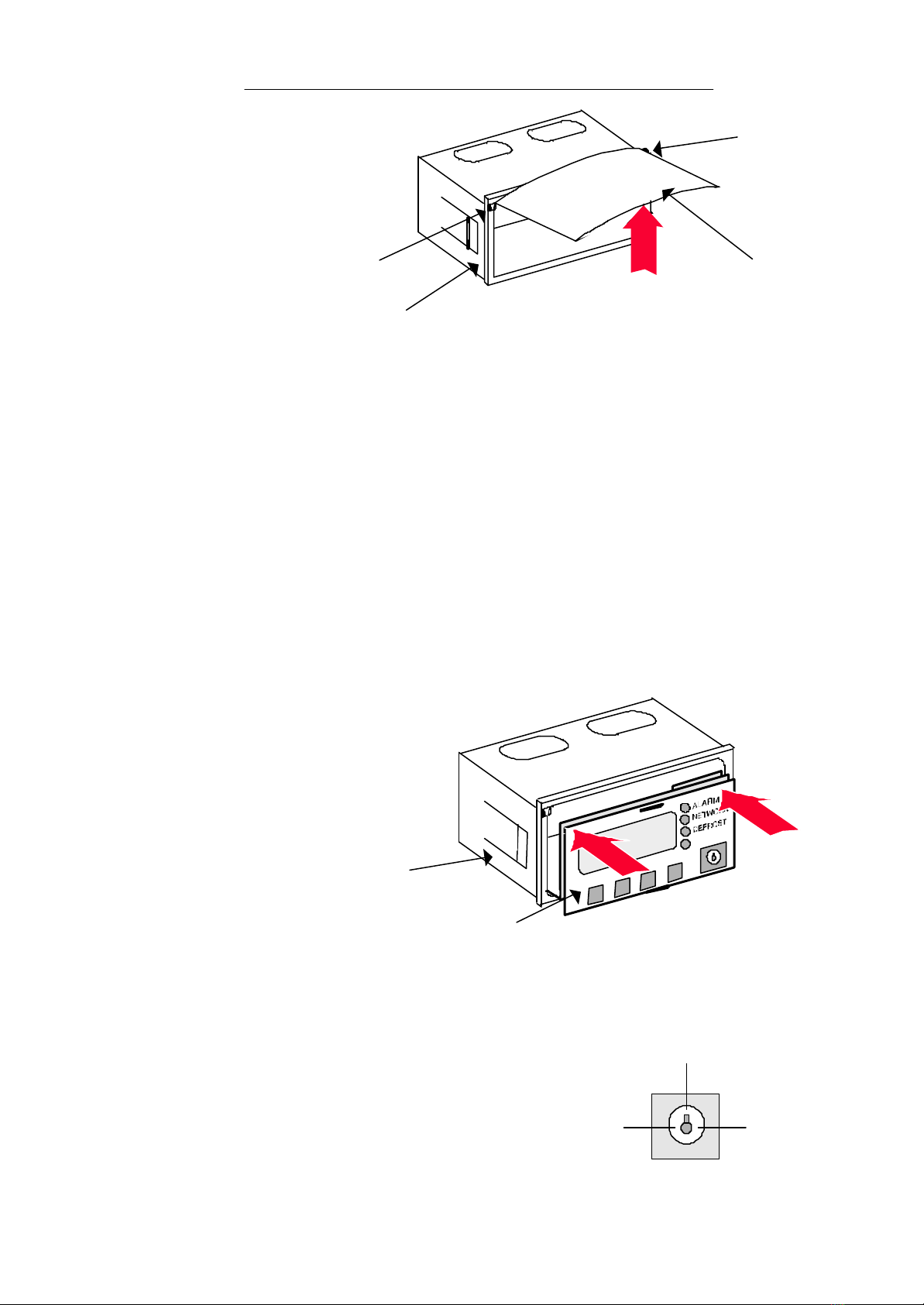
Install Display in Housing (Fig. 3)
When you install the display unit in the housing you
must take up the slack in both cables.
Holding assembly in both hands, with both thumbs
at top of front face, press display into the housing.
The display will snap into position.
Press both lower corners of display unit front face, to
ensure display is seated correctly in housing.
Replace Door Flap (Fig. 2)
Replace door flap by locating one of two tabs (1) in one of the housing tab locations (7) then apply pressure to flap (in
direction of arrow). The door flap should flex until the remaining tab (1) engages with the door flap tab location in
display housing (8). Note: Care must be taken not to apply excess pressure to flap, otherwise damage may occur.
Operation
Make sure ‘Case Type’ parameter is set to Keyswitch option -Refer
to relevant Installation Guide (e.g. DIN function 9 on ZA10221-YDH)
Insert key in keyswitch (2) then turn, either 90 degrees anti-
clockwise to select Red (high) temperature range, or 90 degrees
clockwise to select Yellow (low) temperature range.
The 12 o’clock position switches the case off.
Note: The key may be removed after setting, if desired.
For all other functions, refer to DIN Display User Guide ZF0920-DIN
Red (High)
Temperature
Range
Yellow (Low)
Temperature
Range
Case OFF
1. Tabs
15 Door Flap
8. Display
Housing
7. Tab Locations
Fig. 2
Fig. 3
12. Display unit
8. Display housing